CBSE 12th Standard Physics Subject Electromagnetic Induction Chapter Case Study Questions With Solution 2021
By QB365 on 21 May, 2021
QB365 Provides the updated CASE Study Questions for Class 12 , and also provide the detail solution for each and every case study questions . Case study questions are latest updated question pattern from NCERT, QB365 will helps to get more marks in Exams
QB365 - Question Bank Software
CBSE 12th Standard Physics Subject Electromagnetic Induction Case Study Questions With Solution 2021
12th Standard CBSE
-
Reg.No. :
Physics
-
Lenz's law states that the direction of induced current in a circuit is such that it opposes the change which produces it. Thus, if the magnetic flux linked with a closed circuit increases, the induced current flows in such a direction that magnetic flux is created in the opposite direction of the original magnetic flux. If the magnetic flux linked with the closed circuit decreases, the induced current flows in such a direction so as to create magnetic flux in the direction of the original flux.
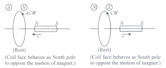
(i) Which of the following statements is correct?(a) The induced e.m.f is not in the direction opposing the change in magnetic flux so as to oppose the cause which produces it. (b) The relative motion between the coil and magnet produces change in magnetic flux. (c) Emf is induced only if the magnet is moved towards coil. (d) Emf is induced only if the coil is moved towards magnet (ii) The polarity of induced emf is given by
(a) Ampere's circuital law (b) Biot-Savart law (c) Lenz's law (d) Fleming's right hand rule (iii) Lenz's law is a consequence of the law of conservation of
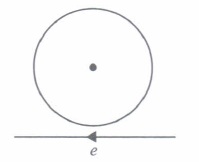
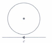
(a) charge (b) mass (c) momentum (d) energy (iv) Near a circular loop of conducting wire as shown in the figure, an electron moves along a straight line. The direction of the induced current if any in the loop is
(a) variable (b) clockwise (c) anticlockwise (d) zero (v) Two identical circular coils A and B are kept in a horizontal tube side by side without touching each other. If the current in coil A increases with time, in response, the coil B.
(a) is attracted by A (c) is repelled (c) is repelled (d) rotates (a) -
Mutual inductance is the phenomenon of inducing emf in a coil, due to a change of current in the neighbouring coil. The amount of mutual inductance that links one coil to another depends very much on the relative positioning of the two coils, their geometry and relative separation between them. Mutual inductance between the two coils increases \(\mu_{r}\) times if the coils are wound over an iron core of relative permeability \(\mu_{r}\).
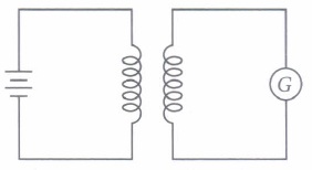
(I) A short solenoid of radius a, number of turns per unit length nI' and length L is kept coaxially inside a very long solenoid of radius b, numbdr of turns per unit length n2• What is the mutual inductance of the system?\(\text { (a) } \mu_{0} \pi b^{2} n_{1} n_{2} L\) \(\text { (b) } \mu_{0} \pi a^{2} n_{1} n_{2} L^{2}\) \(\text { (c) } \mu_{0} \pi a^{2} n_{1} n_{2} L\) \(\text { (d) } \mu_{0} \pi b^{2} n_{1} n_{2} L^{2}\) (ii) If a change in current of 0.01 A in one coil produces a change in magnetic flux of 2 x l0-2 weber in another coil, then the mutual inductance between coils is
(a) 0 (b) 0.5 H (c) 2 H (d) 3 H (iii) Mutual inductance of two coils can be increased by
(a) decreasing the number of turns in the coils (b) increasing the number of turns in the coils (c) winding the coils on wooden cores (d) none of these (iv) When a sheet of iron is placed in between the two co-axial coils, then the mutual inductance between the coils will
(a) increase (b) decrease (c) remains same (d) cannot be predicted (v) The SI unit of mutual inductance is
(a) ohm (b) mho (c) henry (d) none of these (a) -
Currents can be induced not only in conducting coils, but also in conducting sheets or blocks. Current is induced in solid metallic masses when the magnetic flux threading through them changes. Such currents flow in the form of irregularly shaped loops throughout the body of the metal. These currents look like eddies or whirlpools in water so they are known as eddy currents. Eddy currents have both undesirable effects and practically useful applications. For example it causes unnecessary heating and wastage of power in electric motors, dynamos and in the cores of transformers.
(I) The working of speedometers of trains is based on(a) wattless currents (b) eddy currents (c) alternating currents (d) pulsating currents (ii) Identify the wrong statement
(a) Eddy currents are produced in a steady magnetic field (b) Induction furnace uses eddy currents to produce heat. (c) Eddy currents can be used to produce braking force in moving trains (d) Power meters work on the principle of eddy currents. (iii) Which of the following is the best method to reduce eddy currents?
(a) Laminating core (b) Using thick wires (c) By reducing hysteresis loss (d) None ofthese (iv) The direction of eddy currents is given by
(a) Fleming's left hand rule (b) Biot-Savart law (c) Lenz's law (d) Ampere-circuital law (v) Eddy currents can be used to heat localised tissues of the human body. This branch of medical therapy is called
(a) Hyperthermia (b) Diathermy (c) Inductothermy (d) none of these (a) -
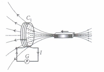
In year 1820 Oersted discovered the magnetic effect of current. Faraday gave the thought that reverse of this phenomenon is also possible i.e., current can also be produced by magnetic field. Faraday showed that when we move a magnet towards the coil which is connected by a sensitive galvanometer. The galvanometer gives instantaneous deflection showing that there is an electric current in the loop.
Whenever relative motion between coil and magnet takes place an emf induced in coil. If coil is in closed circuit then current is also induced in the circuit. This phenomenon is called electromagnetic induction.
(I) The north pole of a long bar magnet was pushed slowly into a short solenoid connected to a galvanometer. The magnet was held stationary for a few seconds with the north pole in the middle of the solenoid and then withdrawn rapidly. The maximum deflection of the galvanometer was observed when the magnet was(a) moving towards the solenoid (b) moving into the solenoid (c) at rest inside the solenoid (d) moving out of the solenoid. (ii) Two similar circular loops carry equal currents in the same direction. On moving the coils further apart, the electric current will
(a) remain unaltered (b) increases in one and decreases in the second (c) increase in both (d) decrease in both (iii) A closed iron ring is held horizontally and a bar magnet is dropped through the ring with its length along the axis of the ring. The acceleration of the falling magnet is
(a) equal to g (b) less than g (c) more than g (d) depends on the diameter of the ring and length of magnet (iv) Whenever there is a relative motion between a coil and a magnet, the magnitude of induced emf set up in the coil does not depend upon the
(a) relative speed between the coil and magnet (b) magnetic moment of the coil (c) resistance of the coil (d) number of turns in the coil (v) A coil of metal wire is kept stationary in a non-uniform magnetic field
(a) an emf and current both are induced in the coil (b) a current but no emf is induced in the coil (c) an emf but no current is induced in the coil (d) neither emf nor current is induced in the coil (a) -
The emf induced across the ends of a conductor due to its motion in a magnetic field is called motional emf. It is produced due to the magnetic Lorentz force acting on the free electrons of the conductor. For a circuit shown in figure, if a conductor of length I moves with velocity v in a magnetic field B perpendicular to both its length and the direction of the magnetic field, then all the induced parametres are possible in the circuit.
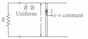
(i) Direction of current induced in a wire moving in a magnetic field is found using(a) Fleming's left hand rule (b) Fleming's right hand rule (c) Ampere's rule (d) Right hand clasp rule (ii) A conducting rod of length I is moving in a transverse magnetic field of strength B with velocity v. The resistance of the rod is R. The current in the rod is
\(\text { (a) } \frac{B l v}{R}\) (b) Blv (c) zero \(\text { (d) } \frac{B^{2} v^{2} l^{2}}{R}\) (iii) A 0.1 m long conductor carrying a current of 50 A is held perpendicular to a magnetic field of 1.25 mT. The mechanical power required to move the conductor with a speed of 1 m s-1 is
(a) 62.5 mW (b) 625 mW (c) 6.25 mW (d) 12.5 mW (iv) A bicycle generator creates 1.5 V at 15 km/hr. The EMF generated at 10 km/hr is
(a) 1.5 volts (b) 2volts (c) 0.5volts (d) 1 volt (v) The dimensional formula for emf E in MKS system will be
\(\text { (a) }\left[\mathrm{ML}^{2} \mathrm{~T}^{-3} \mathrm{~A}^{-1}\right]\) \(\text { (b) }\left[\mathrm{ML}^{2} \mathrm{~T}^{-1} \mathrm{~A}\right]\) \(\text { (c) }\left[\mathrm{ML}^{2} \mathrm{~A}\right]\) \(\text { (d) }\left[\mathrm{MLT}^{-2} \mathrm{~A}^{-2}\right]\) (a)
Part A
*****************************************
CBSE 12th Standard Physics Subject Electromagnetic Induction Case Study Questions With Solution 2021 Answer Keys
-
(i) (b): The relative motion between the coil and the magnet produces change in the magnetic flux in the coil. The induced emf is always in such a direction that it opposes the change in the flux.
(ii) (c)
(iii) (d)
(iv) (a): When an electron is moving from right to left, the flux linked with loop (which is going into the page) will first increase and then decrease as the electron passes by. So the induced current I, in the loop will be first clockwise and will change direction (i.e. will become anticlockwise) as the electron passes by.
(v) (c): When current in coil A increases with time, there will be a change of flux in coil B which will induce a current in B. Now, according to Lenz's law, the direction of induced current in B will be opposite to the direction of current in A. Thus, if two loops carry current in opposite direction they will repel each other. -
(i) (c) :The mutual inductance ofthe system is \(M=\mu_{0} n_{1} n_{2} \pi a^{2} L\)
(ii) (c): Here \(\phi_{B}=2 \times 10^{-2} \mathrm{~Wb}, I=0.01 \mathrm{~A}\)
As \(\phi_{B}=M I\)
\(\therefore\) Mutual inductance between two coils is \(M=\frac{\phi_{B}}{I}=\frac{2 \times 10^{-2} \mathrm{~Wb}}{0.01 \mathrm{~A}}=2 \mathrm{H}\)
(iii) (b) : Mutual inductance of coils \(M=\frac{\mu_{0} \mu_{r} N_{1} N_{2} A}{l}\)
It is clear that mutual inductance of coils can be increased by increasing the number of turns in the coils.
(iv) (a) : We know that the mutual inductance depends (directly proportional) on the permeability of the medium surrounding the coils. When the permeability of the medium is increased by inserting a sheet of iron, then the mutual inductance between the coils also increases.
(v) (c) -
(i) (b) : The working of speedometers is based on eddy currents.
(ii) (a)
(iii) (a): To reduce the eddy currents in the metal armature of motors, wire is wrapped around a number of thin metal sheets called lamination.
(iv) (c) : Eddy currents also oppose the change in magnetic flux, so their direction is given by Lenz's law.
(v) (c) -
(i) (d) : More rapid is the movement of bar magnet, more is the deflection observed in the galvanometer
(ii) (c) : Two circular loops carrying current in the same direction will attract each other. If they are now separated, induced currents will try to keep status quo, by increasing the current in both the coils.
(iii) (b): Acceleration of the magnet will not be equal to g. It will be less than g. This is because, as the magnet falls, amount of magnetic flux linked with the ring changes.
An induced emf is developed in the ring which opposes the downward motion of the magnet.
(iv) (c) : The magnitude of induced emf set up in the coil does not depend upon the resistance of the coil whereas induced current set up in the coil depend upon the resistance of the coil.
(v) (d) : As long as a coil of metal is kept stationary in a magnetic field, even if it is non-uniform, unless it is changing with respect to time, there will be no induced emf or current in the coil. -
(i) (b) : Direction of current induced in a wire moving in a magnetic field is found by using Fleming's right hand rule.
(ii) (a) : Induced e.m.f, E = Blv
Current in the rod, \(I=\frac{\varepsilon}{R}=\frac{B l v}{R}\)
(iii) (c) : Here, L = 0.1 m, v = 1m s-1
\(I=50 \mathrm{~A}, B=1.25 \mathrm{mT}=1.25 \times 10^{-3} \mathrm{~T}\)
The induced emf is, E = Blv
The mechanical power is \(P=\varepsilon I=B l v I=1.25 \times 10^{-3} \times 0.1 \times 1 \times 50\)
\(=6.25 \times 10^{-3} \mathrm{~W}=6.25 \mathrm{~mW}\)
(iv) (d): Emf induced, E = Blv
Here, \(\vec{B}, \vec{l}\) and \(\vec{v}\) are mutually perpendicular
For given B and l,\(\varepsilon \propto v\)
\(\therefore \quad \frac{\varepsilon_{1}}{\varepsilon_{2}}=\frac{v_{1}}{v_{2}}\)
Here, \(\varepsilon_{1}=1.5 \mathrm{~V}, v_{1}=15 \mathrm{~km} / \mathrm{hr}=15 \times \frac{5}{18} \mathrm{~ms}^{-1}\)
\(v_{2}=10 \mathrm{~km} / \mathrm{hr}=10 \times \frac{5}{18} \mathrm{~ms}^{-1}, \varepsilon_{2}=?\)
So,\(\frac{1.5}{\varepsilon_{2}}=\frac{15 \times \frac{5}{18}}{10 \times \frac{5}{18}}=\frac{3}{2} ; \quad \varepsilon_{2}=1 \mathrm{~V}\)
(v) (a): \(\varepsilon=\frac{[W]}{[q]}=\frac{M L^{2} T^{-2}}{A T}=M L^{2} T^{-3} A^{-1}\)
Part A


