
 100% FREE ACCESS
12th Standard Syllabus & Materials
12th Standard
TN 12th Computer Applications மின்னணு தரவு பரிமாற்றம் Sample Question Papers Study Material - QB365 Set A
NEW12th Standard
TN 12th Computer Applications மின் - வணிக பாதுகாப்பு அமைப்புகள் Sample Question Papers Study Material - QB365 Set A
NEW12th Standard
TN 12th Computer Applications மின்னணு செலுத்தல் முறைகள் Sample Question Papers Study Material - QB365 Set A
NEW12th Standard
TN 12th Computer Applications மின் - வணிகம் Sample Question Papers Study Material - QB365 Set A
NEW12th Standard
TN 12th Computer Applications திறந்த மூல கருத்துருக்கள் Sample Question Papers Study Material - QB365 Set A
NEW12th Standard
TN 12th Computer Applications வலையமைப்பு வடமிடல் Sample Question Papers Study Material - QB365 Set A

Published on: 30/09/2019
Electrostatics
Download Tamil Nadu 12th Standard Physics question papers, model tests, one-mark questions, important questions, and public exam papers in PDF format. Free study materials and answer keys for TN State Board students.
Questions + Answers key
Take MCQ Physics Test1.
Write the special features of Gauss law.
2.
Deduce electric flus for closed surfaces.
3.
Derive the expressions for the potential energy of a system of point charges.
4.
Define potential difference and derive.
5.
Deduce an expression for the electric field due to the system of point charges.
6.
Obtain the expression for energy stored in the parallel plate capacitor.
7.
Obtain the expression for capacitance for a parallel plate capacitor.
8.
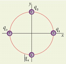
Consider four equal charges q1, q2, q3 and q4 = q = +1 μC located at four different points on a circle of radius 1m, as shown in the figure. Calculate the total force acting on the charge q1 due to all the other charges.
9.
Calculate the electrostatic force and gravitational force between the proton and the electron in a hydrogen atom. They are separated by a distance of 5.3 x 10⁻¹¹ m. The magnitude of charges on the electron and proton are 1.6 x 10⁻¹⁹ C. Mass of the electron is me = 9.1 x 10⁻³¹ kg and mass of proton is mp = 1.6 x 10⁻²⁷ kg.
10.
Explain in detail the effect of a dielectric placed in a parallel plate capacitor.
1.
(i) The total electric flux through the closed surface depends only on the charges enclosed by the surface and the charges present outside the surface will not contribute to the flux and the shape of the closed surface which can be chosen arbitrarily.
(ii) The total electric flux is independent of the location of the charges inside the closed surface.
(iii) To arnve at equation \(\Phi =\oint { \overset { \rightarrow }{ E } .d\overset { \rightarrow }{ A } } =\frac { { Q }_{ encl } }{ { \varepsilon }_{ 0 } } \) is chosen a spherical surface. This imaginary surface is called a Gaussian surface. The shape of the Gaussian surface to be chosen depends on the type of charge configuration and the kind of symmetry existing in that charge configuration. The electric field is spherically symmetric for a point charge, therefore spherical Gaussian surface is chosen. cylindrical and planar Gaussian surfaces can be chosen for other kinds of charge configurations.
(iv) In the L.H.S of equation \(\Phi =\oint { \overset { \rightarrow }{ E } .d\overset { \rightarrow }{ A } } =\frac { { Q }_{ encl } }{ { \varepsilon }_{ 0 } } \) the electric field \(\overset { \rightarrow }{ E } \) is due to charges present inside and outside the Gaussian surface but the charge Qencl denotes the charges which lie only inside the Gaussian surface.
(v) The Gaussian surface cannot pass through any discrete charge but it can pass through continuous charge distributions. It is because, very close to the discrete charges, the electric field is not well defined.
(vi) Gauss law is another form of Coulomb's law and it is also applicable to the charges in motion. Because of this reason, Gauss law is treated as much more general law than Coulomb's law.
2.
(i) A closed surface is present in the region of the non-uniform electric field as shown in Figure (a). The total electric flux over this closed surface is written as
\({ \Phi }_{ E }=\oint { \overset { \rightarrow }{ E } } .d\overset { \rightarrow }{ A } \quad \quad \quad \quad ...(1)\)
(ii) Note the difference between equations \({ \Phi }_{ E }=\int { \overset { \rightarrow }{ E } . } d\overset { \rightarrow }{ A } \) and (1). The integration in equation (1) is a closed surface integration and for each areal element, the outward normal is the direction of d\(\overset { \rightarrow }{ A } \) as shown in the Figure (b).
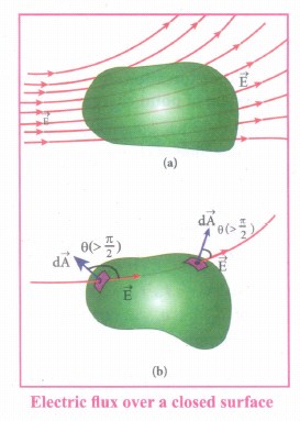
(iii) The total electric flux over a closed surface can be negative, positive or zero. In the Figure (b), it is shown that in one area element, the angle between d\(\overset { \rightarrow }{ A } \) and \(\overset { \rightarrow }{ E } \) is less than 90°, then the electric flux is positive and in another areal element, the angle between d\(\overset { \rightarrow }{ A } \) and \(\overset { \rightarrow }{ E } \) is greater than 90°, then the electric flux is negative.
(iv) In general, the electric flux is negative if the electric field lines enter the closed surface and positive if the electric field lines leave the closed surface.
3.
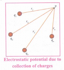
(i) The electric potential at a point P due to a collection of charges q1, q2, q3, ···qn is equal to sum of the electric potentials due to individual charges.
\({ V }_{ tot }=\frac { k{ q }_{ 1 } }{ { r }_{ 1 } } +\frac { { kq }_{ 2 } }{ { r }_{ 2 } } +\frac { { kq }_{ 3 } }{ { r }_{ 3 } } +...\frac { { kq }_{ n } }{ { r }_{ n } } =\frac { 1 }{ 4\pi { \varepsilon }_{ 0 } } { \sum { } }_{ i=1 }^{ n }\frac { { q }_{ i } }{ { r }_{ i } } \)
(ii) where r1, r2, r3 .... rn are the distances of q1, q2, q3 ..... qn respectively from P(Figure).
4.
(i) The potential energy difference per unit charge is given by
\(\frac { \Delta U }{ q' } =\frac { q'\int _{ R }^{ P }{ (-\overset { \rightarrow }{ E } ) } .d\overset { \rightarrow }{ r } }{ q' } =\int _{ R }^{ P }{ \overset { \rightarrow }{ E } } .d\overset { \rightarrow }{ r } \quad ...(1)\)
(ii) The above equation (1) is independent of q'. The quantity \(\frac { \Delta U }{ q' } =\int _{ R }^{ P }{ \overset { \rightarrow }{ E } } .d\overset { \rightarrow }{ r } \) is called electric potential difference between P and R and is denoted as VP - VR = ∆V.
(iii) In other words the electric potential difference is also defined as the work done by an external force to bring unit positive charge from point R to point P.
\({ V }_{ p }-{ V }_{ R }=\Delta V=\int _{ R }^{ P }{ \overset { \rightarrow }{ E } } .d\overset { \rightarrow }{ r } \)
(iv) The electric potential energy difference can be written as ∆U = q' ∆V.
5.
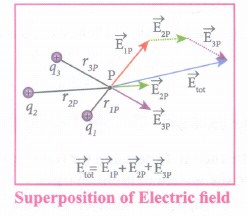
(i) Suppose a number of point charges are distributed in space, to find the electric field at some point P due to this collection of point charges, superposition principle is used.
(ii) The electric field due to a collection of point charges at an arbitrary point is simply equal to the vector sum of the electric fields created by the individual point charges. This is called superposition of electric fields.
(iii) Consider a collection of point charges q1, q2, q3,,....qn located at various points in space. The total electric field at some point P due to all these n charges is given by
\({ \overset { \rightarrow }{ E } }_{ tot }={ \overset { \rightarrow }{ E } }_{ 1 }+{ \overset { \rightarrow }{ E } }_{ 2 }+{ \overset { \rightarrow }{ E } }_{ 3 }+......+{ \overset { \rightarrow }{ E } }_{ n }\quad ...(1)\)
\({ \overset { \rightarrow }{ E } }_{ tot }=\frac { 1 }{ 4\pi { \varepsilon }_{ 0 } } \left\{ \frac { { q }_{ 1 } }{ { r }_{ 1p }^{ 2 } } { \hat { r } }_{ 1p }+\frac { { q }_{ 2 } }{ { r }_{ 2p }^{ 2 } } { \hat { r } }_{ 2p }+\frac { { q }_{ 3 } }{ { q }_{ 3p }^{ 2 } } { \hat { r } }_{ 3p }+...\frac { { q }_{ n } }{ { r }_{ nP }^{ 2 } } { \hat { r } }_{ nP } \right\} (2)\)
(ill) Here r1p, r2p,r3p,········rnP are the distances between the point P and the charges q1P, q2P, q3p..... qnP respectively. Also \({ \hat { r } }_{ 1p },{ \hat { r } }_{ 2p },{ \hat { r } }_{ 3p }\quad ......{ \hat { r } }_{ nP }\) are the unit vectors directed from q1p, q2p,q3p ...... qnP respectively to P. Equation (2) can be re-written as,
\({ \overset { \rightarrow }{ E } }_{ tot }=\frac { 1 }{ 4\pi { \varepsilon }_{ 0 } } \sum _{ i=1 }^{ n }{ \left( \frac { { q }_{ i } }{ { r }_{ ip }^{ 2 } } \hat { r } ip \right) } ....(3)\)
(iv) For example in Figure, the resultant electric field due to three point charges q1,q2,q3, at point P is shown
Note that the relative lengths of the electric field vectors for the charges depend on relative distances of the charges to the point P.
6.
Energy stored in the capacitor
i) Capacitor not only stores the charge but also it stores energy. When a battery is connected to the capacitor, electrons of total charge - Q are transferred from one plate to the other plate. To transfer the charge, work is done by the battery. This work done is stored as electrostatic potential energy in the capacitor.
ii) To transfer an infinitesimal charge dQ for a potential difference V, the work done is given by
dW = V dQ
Where \(V=\frac { Q }{ C } \) .....(1)
iii) The total work done to charge a capacitor is
\(W=\int _{ 0 }^{ Q }{ \frac { Q }{ C } } dQ=\frac { { Q }^{ 2 } }{ 2C } \quad \quad ....(2)\)
This work done is stored as electrostatic potential energy (UE) in the capacitor.
\({ U }_{ E }=\frac { { Q }^{ 2 } }{ 2C } =\frac { 1 }{ 2 } { CV }^{ 2 },\quad (\therefore Q=CV)\quad ....(3)\)
(iv) This stored energy is thus directly proportional to the capacitance of the capacitor and the square of the voltage between the plates of the capacitor.Substituting \(C=\frac { { \varepsilon }_{ 0 }A }{ d } \) and V = Ed.
\(U=\frac { 1 }{ 2 } \left( \frac { { \varepsilon }_{ 0 }A }{ d } \right) { (Ed) }^{ 2 }=\frac { 1 }{ 2 } { \varepsilon }_{ 0 }(Ad){ E }^{ 2 }\quad \quad \quad \quad \quad ...(4)\)
where Ad = volume of the space between the capacitor plates. The energy stored per unit volume of space is defined as energy density \({ u }_{ E }=\frac { U }{ Volume } \)
Equation (4) ⇒ \({ u }_{ E }=\frac{1}{2}{ \varepsilon }_{ 0 }{ E }^{ 2 }\).....(5)
(v) From equation (5),
(a) We infer that the energy is stored in the electric field existing between the plates of the capacitor. Once the capacitor is allowed to discharge, the energy is retrieved.
(b) The energy density depends only on the electric field and not on the size of the plates of the capacitor.
(c) This is true for the electric field due to any type of charge configuration.
7.
Capacitance of a parallel plate capacitor:
(i) Consider a capacitor with two parallel plates each of cross-sectional area A and separated by a distance d as shown in Figure.
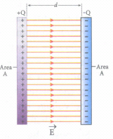
(ii) The electric field between two infinite parallel plates is uniform and is given by \(E=\frac { \sigma }{ { \varepsilon }_{ o} } \) where σ is the surface charge density on the plates \(\left( \sigma =\frac { Q }{ A } \right) \).
iii) If the separation distance d is very much smaller than the size of the plate (d2 < < A), then the above result is used even for finite-sized parallel plate capacitor.
The electric field between the plates is
\(E=\frac { Q }{ A{ \varepsilon }_{ 0 } } ...(1)\)
iv) Since the electric field is uniform, the electric potential between the plates having separation d is given by
\(V=Ed=\frac { Qd }{ A{ \varepsilon }_{ 0 } } \quad \quad \quad ...(2)\)
Therefore the capacitance of the capacitor is given by
\(C=\frac { Q }{ V } =\frac { Q }{ \left( \frac { Qd }{ A{ \varepsilon }_{ 0 } } \right) } =\frac { { \varepsilon }_{ 0 }A }{ d } \quad \quad ....(3)\)
(v) From equation (3), it is evident that capacitance is directly proportional to the area of cross section and is inversely proportional to the distance between the plates.
8.
According to the superposition principle, the total electrostatic force on charge q1 is the vector sum of the forces due to the other charges,
\(\vec { { F }_{ 1 }^{ tot } } =\bar { { F }_{ 12 } } +\bar { { F }_{ 13 } } +\bar { F_{ 14 } } \)
The following diagram shows the direction of each force on the charge q1.
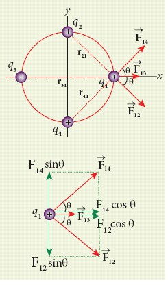
The charges q2 and q4 are equi-distant from q1. As a result the strengths (magnitude) of the forces \(\vec { { F }_{ 12 } } \) and \(\vec { { F }_{ 14 } } \) are the same even though their directions are different. Therefore the vectors representing these two forces are drawn with equal lengths. But the charge q3 is located farther compared to q2 and q4. Since the strength of the electrostatic force decreases as distance increases, the strength of the force \(\vec { { F }_{ 13 } } \) is lesser than that of forces \(\vec { { F }_{ 12 } } \) and \(\vec { { F }_{ 14 } } \). Hence the vector representing the force \(\vec { { F }_{ 13 } } \) is drawn with smaller length compared to that for forces \(\vec { { F }_{ 12 } } \) and \(\vec { { F }_{ 14 } } \).
From the figure, r21 =\(\sqrt { 2 } \) m = r41 and r31 = 2m
The magnitudes of the forces are given by
F13 = \(\frac { kq^{ 2 } }{ r_{ 31 }^{ 2 } } =\frac { 9\times 10^{ 9 }\times 10^{ -12 } }{ 4 } \)
F13 = 2.25 x 10⁻³ N
F12 = \(\frac { kq^{ 2 } }{ r_{ 31 }^{ 2 } } ={ F }_{ 14 }=\frac { 9\times 10^{ 9 }\times 10^{ -12 } }{ 2 } \)
= 4.5 x 10⁻³N
From the figure, the angle θ = 450. In terms of the components, we have
\(\vec { { F }_{ 12 } } ={ F }_{ 12 }cos\theta \hat { i } -{ F }_{ 12 }sin\theta \hat { j } \)
= 4.5 x 10⁻³ x \(\frac { 1 }{ \sqrt { 2 } } \hat { i-4.5\times { 10 }^{ -3 }\times \frac { 1 }{ \sqrt { 2 } } \hat { j } } \)
\(\vec { { F }_{ 13 } } =F_{ 13 }\hat { i } \) = 2.25 x 10⁻³ N\(\hat { i } \)
\(\vec { { F }_{ 14 } } ={ F }_{ 14 }cos\theta \hat { i } +{ F }_{ 14 }sin\theta \hat { j } \)
= 4.5 x 10⁻³ x \(\frac { 1 }{ \sqrt { 2 } } \hat { i+4.5\times { 10 }^{ -3 }\times \frac { 1 }{ \sqrt { 2 } } \hat { j } } \)
Then the total force on q1 is,
\(\vec { { F }_{ 1 }^{ tot } }={ (F }_{ 12 }cos\theta \hat { i } -{ F }_{ 12 }sin\theta \hat { j } )+{ F }_{ 13 }\hat { i } +{ (F }_{ 14 }cos\theta \hat { i } +{ F }_{ 14 }sin\theta \hat { j } )\)
\(\vec { { F }_{ 1 }^{ tot } } =({ F }_{ 12 }cos\theta +F_{13}+{ F }_{ 14 }cos\theta )\hat { i } +(-{ F }_{ 12 }sin\theta +{ F }_{ 14 }sin\theta )\)\(\hat { j } \)
Since F12 = F14, the j th component is zero.
Hence we have
\(\vec { { F }_{ 1 }^{ tot } } =({ F }_{ 12 }cos\theta +F_{13}+{ F }_{ 14 }cos\theta )\hat { i } \)
substituting the values in the above equation,
\(\left( \frac { 4.5 }{ \sqrt { 2 } } +2.25+\frac { 4.5 }{ \sqrt { 2 } } \right) \times10^{-3}\hat { i }=(4.5\sqrt { 2 } +2.25)\times 10^{-3}\hat { i } \)
\(\vec { { F }_{ 1 }^{ tot } } \) = 8.61 x 10⁻³ N\(\hat { i } \)
The resultant force is along the positive x-axis.
9.
The proton and the electron attract each other. The magnitude of the electrostatic force between these two particles is given by
\(F_e=\frac { ke^{ 2 } }{ { r }^{ 2 } } =\frac { 9\times 10^{ 9 }\times (1.6\times 10^{ -19 })^{ 2 } }{ (5.3\times 10^{ -11 })^{ 2 } } \)
=\(\frac { 9\times 2.56 }{ 28.09 } \) x 10-7 = 8.2 x 10⁻⁸ N
The gravitational force between the proton and the electron is attractive. The magnitude of the gravitational force between these particles is
FG = \(\frac { G{ m }_{ e }{ m }_{ p } }{ { r }^{ 2 } } \)
= \(\frac { 6.67\times 10^{ -11 }\times 9.1\times 10^{ -31 }\times 1.6\times 10^{ -27 } }{ (5.3\times 10^{ -11 })^{ 2 } } \)
= \(\frac { 97.11 }{ 28.09 } \) x 10-47 = 3.4 x 10-47N
The ratio of the two forces \(\frac { { F }_{ e } }{ F_{ G } } =\frac { 8.2\times 10^{ -8 } }{ 3.4\times 10^{ -47 } } \)
= 2.41 x 1039
Note that Fe ≈ 1039 FG
The electrostatic force between a proton and an electron is enormously greater than the gravitational force between them. Thus the gravitational force is negligible when compared with the electrostatic force in many situations such as for small size objects and in the atomic domain. This is the reason why a charged comb attracts an uncharged piece of paper with greater force even though the piece of paper is attracted downward by the Earth. This given figure is shown in below.

Electrostatic attraction between a comb and pieces of papers
10.
Effect of dielectrics in capacitors:
Suppose dielectrics like mica, glass or paper are introduced between the plates, then the capacitance of the capacitor is altered. The dielectric can be inserted into the plates in two different ways.
(i) when the capacitor is disconnected from the battery.
(ii) when the capacitor is connected to the battery.
(i) When the capacitor is disconnected from the battery
Consider a capacitor with two parallel plates each of cross-sectional area A and are separated by a distance d. The capacitor is charged by a battery of voltage Vo and the charge stored is Qo. The capacitance of the capacitor without the dielectric is,
\(C_{0}=\frac{Q_{0}}{V_{0}}\) ....(i)
The battery is then disconnected from the capacitor and the dielectric is inserted between the plates. This is shown in Figure.
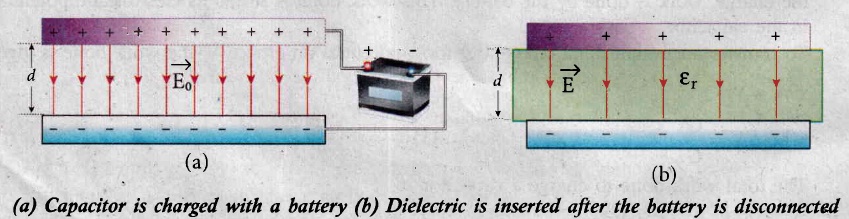
The introduction of dielectric between the plates will decrease the electric field. Experimentally it is found that the modified electric field is given by,
\(E=\frac{E_{0}}{\varepsilon_{r}}\) ....(2)
Here Eo is the electric field inside the capacitors when there is no dielectric and \(\varepsilon_{\mathrm{r}}\) is the relative permittivity of the dielectric or simply known as the dielectric constant. Since \(\varepsilon_{\mathrm{r}}\) > 1, the electric field E < Eo.
As a result, the electrostatic potential difference between the plates (V = Ed) is also reduced. But at the same time, the charge Qo will remain constant once the battery is disconnected.
Hence the new potential difference is
\(V=E d=\frac{E_{0}}{\varepsilon_{r}} d=\frac{V_{0}}{\varepsilon_{r}}\) .......(3)
We know that capacitance is inversely proportional to the potential difference. Therefore as V decreases, C increases.
Thus new capacitance in the presence of a dielectric is
\(C=\frac{Q_{0}}{V}=\varepsilon_{r} \frac{Q_{0}}{V_{0}}=\varepsilon_{r} C_{0}\) ......(4)
Since \(\varepsilon_{\mathrm{r}}\) > 1, we have C > Co. Thus insertion of the dielectric increases the capacitance.
We know that, Co =\(\frac{\varepsilon_{\mathrm{o}} A}{d}\) ...........(5)
Equation (4) ⇒ \(C=\frac{\varepsilon_{r} \varepsilon_{0} A}{d}=\frac{\varepsilon A}{d} \) ..........(6)
where \(\varepsilon=\varepsilon_{\mathrm{r}} \varepsilon_{\mathrm{o}}\) is the permittivity of the dielectric medium.
The energy stored in the capacitor before the insertion of a dielectric is given by,
\(U_{0}=\frac{1}{2} \frac{Q_{0}^{2}}{C_{0}}\) .......(7)
After the dielectric is inserted, the charge Qo remains constant but the capacitance is increased. As a result, the stored energy is decreased.
\(U=\frac{1}{2} \frac{Q_{0}^{2}}{C}=\frac{1}{2} \frac{Q_{0}^{2}}{\varepsilon_{r} C_{0}}=\frac{U_{0}}{\varepsilon_{r}}\) ..........(8)
Since \(\varepsilon_{\mathrm{r}}\) > 1we get U < Uo. There is a decrease in energy because, when the dielectric is inserted, the capacitor spends some energy in pulling the dielectric inside.
(ii) When the battery remains connected to the capacitor:
When the battery of voltage vo remains connected to the capacitor and the dielectric is inserted into the capacitor, then
(a) The potential difference vo across the plates remains constant.
(b) The charge stored in the capacitor is increased by a factor \(\varepsilon_{\mathrm{r}}\). (Experimentally found).
.jpg)
\({Q}=\varepsilon_{r} Q_{0}\) .......(1)
Due to this increased charge, the capacitance is also increased. The new capacitance is,
\(C=\frac{Q}{V_{0}}=\varepsilon_{r} \frac{Q_{0}}{V_{0}}=\varepsilon_{r} C_{0}\) ......(2)
However the reason for the increase in capacitance in this case where the battery remains connected is different from the case when the battery is disconnected before introducing the dielectric.
The energy stored in the capacitor before the insertion of a dielectric is given by,
\(U_{0}=\frac{1}{2} C_{0} V_{0}^{2}\) ....(4)
After the dielectric is inserted, the capacitance is increased; hence the stored energy is also increased.
\( U=\frac{1}{2} C V_{0}^{2}=\frac{1}{2} \varepsilon_{r} C_{0} V_{0}^{2}=\varepsilon_{r} U_{0} \) .....(5)
\(Since \ \varepsilon_{r}>1\ we \ have \ U>U_{o}.\)
Note: Here we have not used the expression \(U_o=\frac{1}{2}\frac{Q_0^2}{C_0}\)because here, both charge and capacitance are changed, whereas in equation (4), Vo remains constant.
Since voltage between the capacitor Vo is constant, the electric field between the plates also remains constant .The energy density is given by,
\(u=\frac{1}{2} \varepsilon E_{0}^{2}\) ..(6)
where ε is the permittivity of the given dielectric material.

12th Standard Syllabus & Materials
12th Standard
TN 12th Computer Applications களப்பெயர் முறைமை (DNS) Sample Question Papers Study Material - QB365 Set A
NEW12th Standard
TN 12th Computer Applications வலையமைப்பு எடுத்துக்காட்டுகள் மற்றும் நெறிமுறைகள் Sample Question Papers Study Material - QB365 Set A
NEW12th Standard
TN 12th Computer Applications கணினி வலையமைப்பு ஓர் அறிமுகம் Sample Question Papers Study Material - QB365 Set A
NEW12th Standard
TN 12th Computer Applications PHP-உடன் MySQL-ஐ இணைத்தல் Sample Question Papers Study Material - QB365 Set A



Tamilnadu Stateboard 12th Standard Subjects

Maths

Chemistry
Physics

Biology

Computer Science

Business Maths and Statistics

Economics

Commerce

Accountancy

History

Computer Applications
Biology
Computer Technology
Computer Applications
Computer Science
Business Maths and Statistics
Commerce
Economics
Maths
Chemistry
Physics
Computer Technology
History
Accountancy

Tamil

English

French
Tamilnadu Stateboard Standards

