
 100% FREE ACCESS
12th Standard Syllabus & Materials
12th Standard
TN 12th Computer Applications மின்னணு தரவு பரிமாற்றம் Sample Question Papers Study Material - QB365 Set A
NEW12th Standard
TN 12th Computer Applications மின் - வணிக பாதுகாப்பு அமைப்புகள் Sample Question Papers Study Material - QB365 Set A
NEW12th Standard
TN 12th Computer Applications மின்னணு செலுத்தல் முறைகள் Sample Question Papers Study Material - QB365 Set A
NEW12th Standard
TN 12th Computer Applications மின் - வணிகம் Sample Question Papers Study Material - QB365 Set A
NEW12th Standard
TN 12th Computer Applications திறந்த மூல கருத்துருக்கள் Sample Question Papers Study Material - QB365 Set A
NEW12th Standard
TN 12th Computer Applications வலையமைப்பு வடமிடல் Sample Question Papers Study Material - QB365 Set A

Published on: 20/01/2020
Download Tamil Nadu 12th Standard Physics question papers, model tests, one-mark questions, important questions, and public exam papers in PDF format. Free study materials and answer keys for TN State Board students.
Questions + Answers key
Take MCQ Physics Test1.
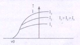
(i) Draw a graph showing variation of photoelectric current (I) with anode potential (V) for different intensities of incident radiation. Name the characteristic of the incident radiation that is kept constant in this experiment.
(ii) If the potential difference used to accelerate electrons is doubled, by what factor does the de-Broglie wavelength associated with the electrons change?
2.
What is robotics?
3.
What are the advantages and Limitations of FM?
4.
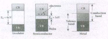
Give the Schematic representation of valence band, conduction band, and forbidden energy gap and draw energy band structure of
(a) Insulators
(b) Semiconductors
(c) Metals?
5.
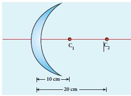
Determine the focal length of the lens made up of a material of refractive index 1.52 as shown in the diagram. (Points C1 and C2 are the centers of curvature of the first and second surfaces respectively.)
6.
A thin rod of length f /3 is placed along the optical axis of a concave mirror of focal length f such that one end of image which is real and elongated just touches the respective end of the rod. Calculate the longitudinal magnification.
7.
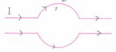
What is the value of the magnetic field at point O due to a current flowing in the wires?
8.
What is impedance? When does LCR circuit have minimum impedance?
9.
Define potential difference and derive.
10.
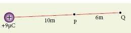
(a) Calculate the electric potential at points P and Q as shown in the figure below.
(b) Suppose the charge + 9μC is replaced by - 9 μC find the electrostatic potentials at points P and Q.
(c) Calculate the work done to bring a test charge +2 μC from infinity to the point Q. Assume the charge +9 μC is held fixed at origin and +2 μC is brought from infinity to P.
11.
Consider a rectangular block of metal of height A, width B and length C as shown in the figure.
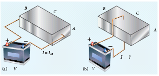
If a potential difference of V is applied between the two faces A and B of the block (figure (a)), the current IAB is observed. Find the current that flows if the same potential difference V is applied between the two faces B and C of the block (figure (b)). Give your answers in terms of IAB.
12.
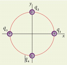
Consider four equal charges q1, q2, q3 and q4 = q = +1 μC located at four different points on a circle of radius 1m, as shown in the figure. Calculate the total force acting on the charge q1 due to all the other charges.
13.
Consider two point charges q1 and q2 at rest as shown in the figure.
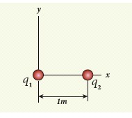
They are separated by a distance of 1m. Calculate the force experienced by the two charges for the following cases:
(a) q1 = +2μC and q2 = +3μC
(b) q1 = +2μC and q2 = -3μC
(c) q1= +2μC and q2 = -3μC kept in water (εr = 80)
14.
In a transistor connected in the common base configuration, \(\alpha\) = 0 95, IE = 1 mA. Calculate the values of IC and IB.
15.
If the focal length is 150 cm for a lens, what is the power of the lens?
16.
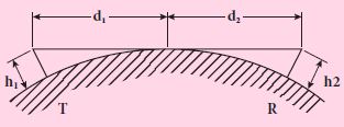
A transmitting antenna has a height of 40 m and the height of the receiving antenna is 30 m. What is the maximum distance between them for line-of-sight communication? The radius of the earth is 6.4 × 10⁶ m.
17.
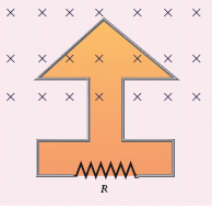
The magnetic flux passes perpendicular to the plane of the circuit and is directed into the paper. If the magnetic flux varies with respect to time as per the following relation \(\Phi_B\) = (2t3 + 3t2 + 8t + 5)mWb, what is the magnitude of the induced emf in the loop when t = 3 s? Find out the direction of current through the circuit.
18.
Obtain the equation for lateral displacement of light passing through a glass slab.
19.
Discuss the Millikan’s oil drop experiment to determine the charge of an electron.
20.
Calculate the magnetic field at a point on the axial line of a bar magnet.
1.
1) The frequency of incident radiation was kept constant.
2) de Broglie wavelength,
\(\lambda =\frac { h }{ \sqrt { 2mqV } } \alpha \frac { 1 }{ V } \)
If potential difference V is doubled, the de-Broglie wavelength is decreased to \(\frac { 1 }{ \sqrt { 2 } } \) time.
2.
(i) Robotics is an integrated study of mechanical engineering, electronic engineering, computer engineering, and science.
(ii) Robot is a mechanical device designed with electronic circuitry and programmed to perform a specific task.
(iii) These automated machines are highly Significant in this robotic era where they can take up the role of humans in certain dangerous environments that are hazardous to people like defusing bombs, finding survivors in unstable ruins, and exploring mines and shipwrecks.
3.
Advantages of AM :
(i) Easy transmission and reception
(ii) Lesser bandwidth requirements
(iii) Low cost
Limitations of AM :
i) Noise level is high
i) Low efficiency
ii) Small operating range
4.
5.
This lens is called convexo-concave lens
Given, n = 1.52, R1 = 10 cm and R2 = 20 cm
Both R1 and R2 are positive
Lens makers formula,
\(\cfrac { 1 }{ f } =\left( n-1 \right) \left( \cfrac { 1 }{ { R }_{ 1 } } -\cfrac { 1 }{ { R }_{ 2 } } \right) \)
Substituting the values,
\(\cfrac { 1 }{ f } =\left( 1.52-1 \right) \left( \cfrac { 1 }{ 10 } -\cfrac { 1 }{ 20 } \right) \)
\(\cfrac { 1 }{ f } =\left( 0.52 \right) \left( \cfrac { 2-1 }{ 20 } \right) =\left( 0.52 \right) (\frac{1}{20})=\cfrac { 0.52 }{ 20 } \)
\(f=\cfrac { 20 }{ 0.52 } =38.46cm\)
As the focal length is positive, the lens is a converging lens.
6.
\(\text{ longitudinal magnifcation}(m_l)=\frac { length\ of\ image\left( l' \right) }{ length\ of\ object\left( l \right) } \)
Given: length of object, \(l=\cfrac { f }{ 3 } \)
For the given condition, the image formation is shown in the figure.
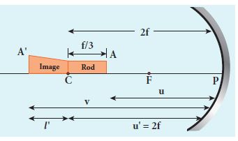
Let, l' be the length of the image, then
\(m=\cfrac { l' }{ l } =\cfrac { l' }{ f/3 } \) (or) \(l=\cfrac { m_lf }{ 3 } \)
Image of one end coincides with the object. Thus, the coinciding end must be at center of curvature.
\(u_B=u_A-\cfrac { f }{ 3 } =2f-\cfrac { f }{ 3 } =\cfrac { 5f }{ 3 } \)
\(v_B=u_B+l+l'\)
\(v_b =\cfrac { 5f }{ 3 } +\cfrac { f }{ 3 } +\cfrac { mf }{ 3 } =\cfrac { f(6+m) }{ 3 } \)
Mirror equation,\(\cfrac { 1 }{ v } +\cfrac { 1 }{ u } =\cfrac { 1 }{ f } \)
\(\cfrac { 1 }{ -\left( \cfrac { f(6+m_l) }{ 3 } \right) } +\cfrac { 1 }{ -\left( \cfrac { 5f }{ 3 } \right) } =\cfrac { 1 }{ -f } \)
After simplifying,
\(\cfrac { 3 }{ f(6+m_l) } +\cfrac { 3 }{ 5f } =\cfrac { 1 }{ f } ;\cfrac { 3 }{ (6+m_l) } =\cfrac { 2 }{ 5 } \)
\(6+m_l=\cfrac { 15 }{ 2 } ;m_l=\cfrac { 15 }{ 2 } -6\)
\(m_l=\cfrac { 3 }{ 2 } =1.5\)
7.
The magnetic field at point O is zero. Because the upper and lower current carrying conductors are identical and so the magnetic fields caused by them at centre O will be equal and opposite.
8.
(i) The total resistance offered to the flow of current due to resistance R, inductive resistance XL, and capacitive reactance Xc in a circuit is called impedance.
It is given by \(z=\sqrt { { R }^{ 2 }+({ { X }_{ L }-{ X }_{ C }) }^{ 2 } } \)
(ii) At resonance, when XL= XC
9.
(i) The potential energy difference per unit charge is given by
\(\frac { \Delta U }{ q' } =\frac { q'\int _{ R }^{ P }{ (-\overset { \rightarrow }{ E } ) } .d\overset { \rightarrow }{ r } }{ q' } =\int _{ R }^{ P }{ \overset { \rightarrow }{ E } } .d\overset { \rightarrow }{ r } \quad ...(1)\)
(ii) The above equation (1) is independent of q'. The quantity \(\frac { \Delta U }{ q' } =\int _{ R }^{ P }{ \overset { \rightarrow }{ E } } .d\overset { \rightarrow }{ r } \) is called electric potential difference between P and R and is denoted as VP - VR = ∆V.
(iii) In other words the electric potential difference is also defined as the work done by an external force to bring unit positive charge from point R to point P.
\({ V }_{ p }-{ V }_{ R }=\Delta V=\int _{ R }^{ P }{ \overset { \rightarrow }{ E } } .d\overset { \rightarrow }{ r } \)
(iv) The electric potential energy difference can be written as ∆U = q' ∆V.
10.
(a) Electric potential at point P is given by
Vp=\(\frac { 1 }{ 4\pi { \varepsilon }_{ 0 } } \frac { q }{ { r }_{ p } } =\frac { 9\times 10^{ 9 }\times 9\times { 10 }^{ -6 } }{ 10 } \) = 8.1 x 10³ V
Electric potential at point Q is given by
VQ = \(\frac { 1 }{ 4\pi { \varepsilon }_{ 0 } } \frac { q }{ { r }_{ Q } } =\frac { 9\times 10^{ 9 }\times 9\times { 10 }^{ -6 } }{ 16 } \) = 5.06 x 10³ V
Note that the electric potential at point Q is less than the electric potential at point P. If we put a positive charge at P, it moves from P to Q. However if we place a negative charge at P it will move towards the charge +9μC.
The potential difference between the points P and Q is given by
ΔV = Vp-VQ = +3.04 x 10³ V
b) Suppose we replace the charge +9 μC by -9 μC, then the corresponding potentials at the points P and Q are,
Vp = -8.1 x 10³ V, VQ = -5.06 x 10³ V
Note that in this case electric potential at the point Q is higher than at point P.
The potential difference or voltage between the points P and Q is given by
ΔV = Vp-VQ= -3.04 x 10³V
(c) The electric potential V at a point P due to some charge is defined as the work done by an external force to bring a unit positive charge from infinity to P. So to bring the q amount of charge from infinity to the point P, work done is given as follows.
W = qV
WQ = 2 x 10-6 x 5.06 x 103J = 10.12 x 10⁻³ J.
11.
In the first case, the resistance of the block
\({ R }_{ AB }=\rho \frac { length }{ Area } =\rho \frac { C }{ AB } \)
The current \({ I }_{ AB }=\frac { V }{ { R }_{ AB } } =\frac { V }{ \rho } .\frac { AB }{ C } \quad (1)\)
In the second case, the resistance of the block \({ R }_{ BC }=\rho \frac { A }{ BC } \)
The current \({ I }_{ BC }=\frac { V }{ { R }_{ BC } } =\frac { V }{ \rho } .\frac { BC }{ C } \quad (2)\)
To express IBC interms of IAB, we multiply and divide equation (2) by AC, we get
\({ I }_{ BC }=\frac { V }{ \rho } .\frac { BC }{ A } \frac { AC }{ AC } =\left( \frac { V }{ \rho } .\frac { AB }{ C } \right) .\frac { { C }^{ 2 } }{ { A }^{ 2 } } =\frac { { C }^{ 2 } }{ { A }^{ 2 } }.{ I }_{ AB }\)
Since C > A, the current IBC > IAB
12.
According to the superposition principle, the total electrostatic force on charge q1 is the vector sum of the forces due to the other charges,
\(\vec { { F }_{ 1 }^{ tot } } =\bar { { F }_{ 12 } } +\bar { { F }_{ 13 } } +\bar { F_{ 14 } } \)
The following diagram shows the direction of each force on the charge q1.
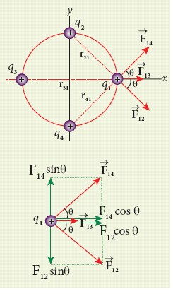
The charges q2 and q4 are equi-distant from q1. As a result the strengths (magnitude) of the forces \(\vec { { F }_{ 12 } } \) and \(\vec { { F }_{ 14 } } \) are the same even though their directions are different. Therefore the vectors representing these two forces are drawn with equal lengths. But the charge q3 is located farther compared to q2 and q4. Since the strength of the electrostatic force decreases as distance increases, the strength of the force \(\vec { { F }_{ 13 } } \) is lesser than that of forces \(\vec { { F }_{ 12 } } \) and \(\vec { { F }_{ 14 } } \). Hence the vector representing the force \(\vec { { F }_{ 13 } } \) is drawn with smaller length compared to that for forces \(\vec { { F }_{ 12 } } \) and \(\vec { { F }_{ 14 } } \).
From the figure, r21 =\(\sqrt { 2 } \) m = r41 and r31 = 2m
The magnitudes of the forces are given by
F13 = \(\frac { kq^{ 2 } }{ r_{ 31 }^{ 2 } } =\frac { 9\times 10^{ 9 }\times 10^{ -12 } }{ 4 } \)
F13 = 2.25 x 10⁻³ N
F12 = \(\frac { kq^{ 2 } }{ r_{ 31 }^{ 2 } } ={ F }_{ 14 }=\frac { 9\times 10^{ 9 }\times 10^{ -12 } }{ 2 } \)
= 4.5 x 10⁻³N
From the figure, the angle θ = 450. In terms of the components, we have
\(\vec { { F }_{ 12 } } ={ F }_{ 12 }cos\theta \hat { i } -{ F }_{ 12 }sin\theta \hat { j } \)
= 4.5 x 10⁻³ x \(\frac { 1 }{ \sqrt { 2 } } \hat { i-4.5\times { 10 }^{ -3 }\times \frac { 1 }{ \sqrt { 2 } } \hat { j } } \)
\(\vec { { F }_{ 13 } } =F_{ 13 }\hat { i } \) = 2.25 x 10⁻³ N\(\hat { i } \)
\(\vec { { F }_{ 14 } } ={ F }_{ 14 }cos\theta \hat { i } +{ F }_{ 14 }sin\theta \hat { j } \)
= 4.5 x 10⁻³ x \(\frac { 1 }{ \sqrt { 2 } } \hat { i+4.5\times { 10 }^{ -3 }\times \frac { 1 }{ \sqrt { 2 } } \hat { j } } \)
Then the total force on q1 is,
\(\vec { { F }_{ 1 }^{ tot } }={ (F }_{ 12 }cos\theta \hat { i } -{ F }_{ 12 }sin\theta \hat { j } )+{ F }_{ 13 }\hat { i } +{ (F }_{ 14 }cos\theta \hat { i } +{ F }_{ 14 }sin\theta \hat { j } )\)
\(\vec { { F }_{ 1 }^{ tot } } =({ F }_{ 12 }cos\theta +F_{13}+{ F }_{ 14 }cos\theta )\hat { i } +(-{ F }_{ 12 }sin\theta +{ F }_{ 14 }sin\theta )\)\(\hat { j } \)
Since F12 = F14, the j th component is zero.
Hence we have
\(\vec { { F }_{ 1 }^{ tot } } =({ F }_{ 12 }cos\theta +F_{13}+{ F }_{ 14 }cos\theta )\hat { i } \)
substituting the values in the above equation,
\(\left( \frac { 4.5 }{ \sqrt { 2 } } +2.25+\frac { 4.5 }{ \sqrt { 2 } } \right) \times10^{-3}\hat { i }=(4.5\sqrt { 2 } +2.25)\times 10^{-3}\hat { i } \)
\(\vec { { F }_{ 1 }^{ tot } } \) = 8.61 x 10⁻³ N\(\hat { i } \)
The resultant force is along the positive x-axis.
13.
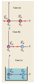
(a) q1 = +2 μC, q2 = +3 μC, and r = 1m. Both are positive charges. so the force will be repulsive.
Force experienced by the charge q2 due to q1 is given by
\(\vec { { F }_{ 21 } } =\frac { 1 }{ 4\pi { \varepsilon }_{ 0 } } \frac { { q }_{ 1 }{ q }_{ 2 } }{ { r }^{ 2 } } \hat { r_{ 12 } } \)
Here \(\hat { r_{ 12 } } \) is the unit vector from q1 to q2. Since q2 is located on the right of q1, we have
\(\hat { r_{ 12 } } =\hat { i } \), and \(\frac { 1 }{ 4\pi { \varepsilon }_{ 0 } }=9 \times10^9\) so that
\(\vec { { F }_{ 21 } } =\frac { 9\times 10^{ 9 }\times 2\times 10^{ -6 }\times 3\times 10^{ -6 } }{ 1^{ 2 } } \hat { i } \)
= 54 x 10-3 N\(\hat { i } \)
According to Newton’s third law, the force experienced by the charge q1 due to q2 is \(\vec { { F }_{ 12 } } =-\vec { { F }_{ 21 } } \) Therefore,
\(\vec { F_{ 12 } } \)= 54 x 10-3 N\(\hat { i } \)
The directions of \(\vec { { F }_{ 21 } } \) and \(\vec { { F }_{ 12 } } \) are shown in the figure (case (b)).
(b) q1 = +2 μC, q2 = –3 μC, and r = 1m. They are unlike charges. So the force will be attractive.
Force experienced by the charge q2 due to q1 is given by
\( \vec{F}_{21} =\frac{9 \times 10^{9} \times\left(2 \times 10^{-6}\right) \times\left(-3 \times 10^{-6}\right)}{1^{2}} \hat{r}_{12} \)
\(=-54 \times 10^{-3} \mathrm{~N} \hat{i}\left(\mathrm{Using} \hat{r}_{12}=\hat{i}\right)\)
The charge q2 will experience an attractive force towards q1 which is in the negative x direction.
According to Newton’s third law, the force experienced by the charge q1 due to q2 is \(\vec{F}_{12}=-\vec{F}_{21}\) Therefore,
\(\vec{F}_{12}=54 \times 10^{-3} \widehat{i} \mathrm{~N}\)
The directions of \(\vec{F}_{21} \text { and } \vec{F}_{12}\) are shown in the figure (case (b)).
(c) If these two charges are kept inside the water, then the force experienced by q2 due to q1
\(\vec { { F }_{ 21 }^{ W } } =\frac { 1 }{ 4\pi { \varepsilon }_{ 0 } } \frac { { q }_{ 1 }{ q }_{ 2 } }{ { r }^{ 2 } } \hat { r_{ 12 } } \)
since ε = εrε0,
we have \(\vec { { F }_{ 21 }^{ W } } =\frac { 1 }{ 4\pi { { \varepsilon }_{ r }\varepsilon }_{ 0 } } \frac { { q }_{ 1 }{ q }_{ 2 } }{ { r }^{ 2 } } \hat { r_{ 12 } } =\frac { \vec { F_{ 21 } } }{ { \varepsilon }_{ r } } \)
Therefore,
\(\vec { { F }_{ 21 }^{ W } } =\frac { 54\times { 10 }^{ -3 }N }{ 80 } \hat { i } \) = -0.675 x 10⁻³ N\(\hat { i } \)
14.
α = \(\frac{I_C}{I_E}\)
IC = α IE = 0.95 x 1 = 0.95 mA
IE = IB + IC
∴ IB = IE - IC = 1 - 0.95 = 0.05 mA
15.
Given, focal length, f = 150 cm = 1.5 m
Equation for power of lens is, \(p=\cfrac { 1 }{ f } \)
Substituting the values,
\(p=\cfrac { 1 }{ 1.5 } =0.67 D\)
As the power is positive, it is a converging lens.
16.
The total distance d between the transmitting and receiving antennas will be the sum of the individual distances of coverage.
d = d1 + d2
\(=\sqrt { 2R{ h }_{ 1 } } +\sqrt { 2{ Rh }_{ 2 } } \)
\(=\sqrt { 2R } \left( \sqrt { { h }_{ 1 } } +\sqrt { { h }_{ 2 } } \right) \)
\(=\sqrt { 2\times 6.4\times { 10 }^{ 6 } } \times (\sqrt { 40 } +\sqrt { 30 } )\)
\(=16\times { 10 }^{ 2 }\sqrt { 5 } \times (6.32+5.48)\)
= 42217 m = 42.217 km
17.
\(\Phi_B\) = (2t3 + 3t2 + 8t + 5)mWb; N = 1;t = 3 s
i) \(ε=\frac { d(N{ \Phi }_{ B }) }{ dt } \)
\(=\frac { d }{ t } \left( { 2t }^{ 3 }+{ 3t }^{ 2 }+8t+5 \right) \times { 10 }^{ -3 }\)
= (6t2 + 6t + 8) x 10-3 V
At t = 3 s,
ε = [( 6 x 9) + (6 x 3) + 8] x 10-3
= 80 x 10-3V = 80mV
(ii) As time passes, the magnetic flux linked with the loop increases. According to Lenz’s law, the direction of the induced current should be in a way so as to oppose the flux increase. So, the induced current flows in such a way to produce a magnetic field opposite to the given field. This magnetic field is perpendicularly outwards. Therefore, the induced current flows in anticlockwise direction.
18.
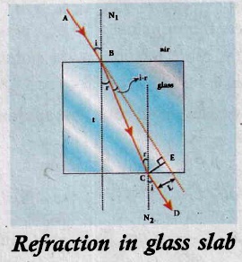
(i) Consider a glass slab of thickness t and refractive index n is kept in air medium.
(ii) If path of the light is ABCD and the refractions occur at two points B and C in the glass slab.
(iii) The angles of incidence i and refraction r are measured with respect to the normal N1 and N2 at the two points Band C respectively. The lateral displacement 'L' is the perpendicular distance CE drawn between the path of light and the undeviated light at point C. In the right angle triangle ΔBCE,
\(sin(i-r)=\frac{1}{BC};BC=\cfrac { L }{ sin(i-r) } \) ..(1)
In the right angle triangle ΔBCF,
\(cos(r)=\cfrac { t }{ BC } ;BC=\cfrac { t }{ cos(r) } \)
Equating equation (1) and (2),
\(\cfrac { L }{ sin(i-r) } =\cfrac { t }{ cos(r) } \)
After rearranging,
\(L=t\left( \cfrac { sin(i-r) }{ cos(r) } \right) \)
(iv) Lateral displacement depends upon
(a) the thickness of the slab
(b) the angle of incidence
(c) the refractive index of the slab.
(v) Thicker the slab, larger will be the lateral displacement. Greater the angle of incidence, larger will be the lateral displacement.
(vi) Higher the refractive index, larger will be the lateral displacement.
19.
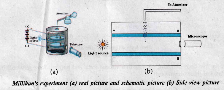
The motion of oil drop inside the chamber can be controlled by adjusting electric field. The oil drop can be moved up or down or even kept balanced in the field of view for sufficiently long time.
Construction:
(i) The apparatus consists of two horizontal circular metal plates A and B each with diameter around 20 cm and are separated by a small distance 1.5 cm.
(ii) These two parallel plates are enclosed in a chamber with glass walls.
(iii) Plates A and B are given a high potential difference around 10 kV such that electric field acts vertically downward
(iv) A small hole is made at the center of the upper plate A.
(v) Atomizer is kept above the hole to spray the liquid.
Working:
(i) When a fine droplet of highly viscous liquid (like glycerine) is sprayed using atomizer, it falls freely downward through the hole under the influence of gravity alone.
(ii) Few oil drops in the chamber can acquire electric charge (negative charge) because of friction with air or passage of x-rays in between the parallel plates.
(iii) The chamber is illuminated by light and oil drops can be seen clearly using microscope.
(iv) These drops can move either upwards or downward.
(v) Let m be the mass of the oil drop and q be its charge. Then the forces acting on the droplet are
(a) gravitational force Fg = mg
(b) electric force Fe = qE
(c) buoyant force Fb
(d) viscous force Fv
(a) Determination of radius of the droplet:
(i) When the electric field is switched off, the oil drop accelerates downwards. Due to presence of air drag forces, the oil drops attain its terminal velocity and moves with constant velocity.
(ii) This velocity can be measured by finding the time taken by the oil drop to fall through a predetermined distance.
.jpg)
(iii) From the free body diagram, we note that viscous force and buoyant force (upward) balance the gravitational force (downward).
(iv) Let us assume that oil drop to be spherical in shape.
(v) Let p be the density of the oil drop, and r be the radius of the oil drop, then the mass of the oil drop, the oil drop can be expressed in terms of its density as, \( \rho=m/v \Rightarrow m=\left(\frac{4}{3} \pi r^{3}\right) \rho\)
∵ (Volume of the sphere, V = \(\frac{4}{3} \pi r^{3})\)
Then gravitational force \(\mathrm{F}_{\mathrm{g}}=\mathrm{mg}=\left(\frac{4}{3} \pi \mathrm{r}^{3}\right) \rho g\)
(vi) Let σ be the density of air, the upthrust force experienced by the oil drop due to displaced air is \(F_{b}=\left(\frac{4}{3} \pi r^{3}\right) σ g\)
(vii) Once the oil drop attains a terminal velocity v, the net downward force acting on the oil drop is equal to the viscous force acting opposite to the direction of motion of the oil drop. From Stokes law, the viscous force on the oil drop is
\(\mathrm{F}_{\mathrm{v}}=6 \pi \eta \mathrm{rv}\)
(ix) From free body diagram, the force balancing equation is,
\(F_{g}=F_{b}+F_{v} \)
\(\left(\frac{4}{3} \pi r^{3}\right) \rho g=\left(\frac{4}{3} \pi r^{3}\right) \sigma g+6 \pi \eta r v \)
\(\frac{4}{3} \pi r^{3}(\rho-\sigma) g=6 \pi \eta r v \)
\(\frac{2}{3} r^{2}(\rho-\sigma) g=3 \eta v \)
Hence radius of the oil drop is \(r=\left[\frac{9 \eta v}{2(\rho-\sigma) g}\right]^{\frac{1}{2}} \ldots\) ........(1)
(b) Determination of electric charge:
(i) Now switch on the electric field.
(ii) Upward electric force on charged oil drops is qE.
(iii) Choose any one drop in the field of view of microscope.
(iv) Strength of the electric field is adjusted to make that particular drop to be stationary.
(v) Being oil drop is at rest, the viscous force acting on the oil drop is zero.
(vi) Then, from the free body diagram.
\(F_{g}=F_{b}+F_{v} \)
\(\left(\frac{4}{3} \pi r^{3}\right) \rho g=\left(\frac{4}{3} \pi r^{3}\right) \sigma g+q E \)
\(\frac{4}{3} \pi r^{3}(\rho-\sigma) g=q E \)
\(q=\frac{4}{3 E} \pi r^{3}(\rho-\sigma) g \ldots \ldots \ldots \ldots \ldots \) (2)
Substituting (1) in (2)
\(q=\frac{18 \pi}{E}\left(\frac{\eta^{3} v^{3}}{2(\rho-\sigma) g}\right)^{\frac{1}{2}}\)
(vii) Millikan repeated this experiment several times and computed the charges on oil drops. He found that the charge of any oil drop can be written as integral multiple of a basic value, -1.6 x 10⁻¹⁹ C which is nothing but the charge of an electron.
20.
(i) Consider a bar magnet NS whose pole strength is qm and length is 2l.
(ii) Let C be the point along axis of maget.
(iii) The magnetic field at a point C (lies along the axis of the magnet) at a distance r from the geometrical center O of the bar magnet can be computed by keeping unit north pole (qmc = 1 A m) at C.
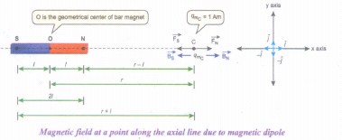
The magnetie field at C due to the north pole is,
\(\vec { { B }_{ N } } =\frac { { \mu }_{ 0 } }{ 4\pi } \frac { { q }_{ m } }{ (r-l)^{ 2 } } \hat { i } \)
where (r - I) is the distance between north pole of the bar magnet and unit north pole at C. The magnetic field at C due to the south pole is,
\(\vec { { B }_{ S } } =-\frac { { \mu }_{ 0 } }{ 4\pi } \frac { { q }_{ m } }{ (r+l)^{ 2 } } \hat { i } \)
where (r + I) is the distance between south pole of the bar magnet and unit north pole at C. The net magnetic field due to magnetic dipole at a point C
\(\vec { B } =\vec { { B }_{ N } } +\vec { B_{ S } } \)
\(\vec { B } =\frac { { \mu }_{ 0 } }{ 4\pi } \frac { { q }_{ m } }{ (r-l)^{ 2 } } \hat { i } +\left(- \frac { { \mu }_{ 0 } }{ 4\pi } \frac { { q }_{ m } }{ (r+l)^{ 2 } } \hat { i } \right) \)
\(\vec { B } =\frac { { \mu }_{ 0 }{ q }_{ m } }{ 4\pi } \left( \frac { 1 }{ (r-l)^{ 2 } } -\frac { 1 }{ (r+l)^{ 2 } } \right) \hat { i } \)
\(\vec { B } =\frac { { \mu }_{ 0 }2r }{ 4\pi } \left( \frac { { q }_{ m }.(2l) }{ ({ r }^{ 2 }-{ l }^{ 2 })^{ 2 } } \right) \hat { i } \)
Since, magnitude of magnetic dipole moment is \(|\vec { { p }_{ m } } |\) = pm = qm. 2l the magnetic field at a point C can be written as,
\(\vec { { B }_{ axial } } =\frac { { \mu }_{ 0 } }{ 4\pi } \left( \frac { 2rp_{ m } }{ { (r^2-l^2)}^{ 2 } } \right) \hat { i } \)
If r >> I then, (r2 - l2)2 ≈ r4
\( { { \vec B }_{ axial } } =\frac { { \mu }_{ 0 } 2r}{ 4\pi } \left( \frac { p_{ m } }{ { r }^{ 4 } } \right) \hat { i } =\frac { { \mu }_{ 0 } }{ 4\pi }[ \frac { 2 \vec p_{ m } }{ { r }^{ 3 }}] \)
∵ \(\vec { { p }_{ m } } =p_{ m }\hat { i } \).

12th Standard Syllabus & Materials
12th Standard
TN 12th Computer Applications களப்பெயர் முறைமை (DNS) Sample Question Papers Study Material - QB365 Set A
NEW12th Standard
TN 12th Computer Applications வலையமைப்பு எடுத்துக்காட்டுகள் மற்றும் நெறிமுறைகள் Sample Question Papers Study Material - QB365 Set A
NEW12th Standard
TN 12th Computer Applications கணினி வலையமைப்பு ஓர் அறிமுகம் Sample Question Papers Study Material - QB365 Set A
NEW12th Standard
TN 12th Computer Applications PHP-உடன் MySQL-ஐ இணைத்தல் Sample Question Papers Study Material - QB365 Set A



Tamilnadu Stateboard 12th Standard Subjects

Maths

Chemistry
Physics

Biology

Computer Science

Business Maths and Statistics

Economics

Commerce

Accountancy

History

Computer Applications
Biology
Computer Technology
Computer Applications
Computer Science
Business Maths and Statistics
Commerce
Economics
Maths
Chemistry
Physics
Computer Technology
History
Accountancy

Tamil

English

French
Tamilnadu Stateboard Standards

