
 100% FREE ACCESS
12th Standard Syllabus & Materials
12th Standard
TN 12th Computer Applications மின்னணு தரவு பரிமாற்றம் Sample Question Papers Study Material - QB365 Set A
NEW12th Standard
TN 12th Computer Applications மின் - வணிக பாதுகாப்பு அமைப்புகள் Sample Question Papers Study Material - QB365 Set A
NEW12th Standard
TN 12th Computer Applications மின்னணு செலுத்தல் முறைகள் Sample Question Papers Study Material - QB365 Set A
NEW12th Standard
TN 12th Computer Applications மின் - வணிகம் Sample Question Papers Study Material - QB365 Set A
NEW12th Standard
TN 12th Computer Applications திறந்த மூல கருத்துருக்கள் Sample Question Papers Study Material - QB365 Set A
NEW12th Standard
TN 12th Computer Applications வலையமைப்பு வடமிடல் Sample Question Papers Study Material - QB365 Set A

Published on: 04/11/2019
Optics
Download Tamil Nadu 12th Standard Physics question papers, model tests, one-mark questions, important questions, and public exam papers in PDF format. Free study materials and answer keys for TN State Board students.
Questions + Answers key
Take MCQ Physics Test1.
Mention different parts of spectrometer and explain the preliminary adjustments.
2.
Obtain the equation for bandwidth in Young’s double slit experiment.
3.
Explain the experimental determination of refractive index of the material of the prism using spectrometer.
4.
Discuss the interference in thin films and obtain the equations for constructive and destructive interference for transmitted and reflected light.
5.
Explain the Young’s double slit experimental setup and obtain the equation for path difference.
6.
Obtain the equation for resultant intensity due to interference of light.
7.
What is the focal length of the combination if the lenses of focal lengths –70 cm and 150 cm are in contact? What is the power of the combination?
8.
A biconvex lens has radii of curvature 20 cm and 15 cm for the two curved surfaces. The refractive index of the material of the lens is 1.5.
(a) What is its focal length?
(b) Will the focal length change if the lens is flipped by the side?
9.
The thickness of a glass slab is 0.25 m. It has a refractive index of 1.5. A ray of light is incident on the surface of the slab at an angle of 60o. Find the lateral displacement of the light when it emerges from the other side of the glass slab.
10.
Discuss about astronomical telescope.
11.
Obtain the equation for of microscope.
12.
A monochromatic light is incident on an equilateral prism at an angle 30o and is emergent at an angle of 75o . What is the angle of deviation produced by the prism?
13.
A optical fibre is made up of a core material with refractive index 1.68 and a cladding material of refractive index 1.44. What is the acceptance angle of the fibre if it is kept in air medium without any cladding?
14.
A coin is at the bottom of a trough containing three immiscible liquids of refractive indices 1.3, 1.4 and 1.5 poured one above the other of heights 30 cm, 16 cm, and 20 cm respectively. What is the apparent depth at which the coin appears to be when seen from air medium outside? In which medium the coin will appear?
15.
Light travelling through transparent oil enters in to glass of refractive index 1.5. If the refractive index of glass with respect to the oil is 1.25, what is the refractive index of the oil?
1.
i) The spectrometer is an optical instrument used to analyse the spectra of different sources of light, to measure the wavelength of different colours and to measure the refractive indices of materials of prisms.
ii) It basically consists of three parts namely. They are (i) collimator, (ii) prism table and (iii) Telescope
Adjustments of the spectrometer
(i) The following adjustments must be done in a spectrometer before doing the experiment.
(a) Adjustment of the eyepiece:
The telescope is turned towards an illuminated surface and the eyepiece is moved to and fro until the cross wires are clearly seen.
(b) Adjustment of the telescope:
The telescope is adjusted to' receive parallel rays by turning it towards a distant object and adjusting the distance between the objective lens and the eyepiece to get a clear image on the cross wire.
(c) Adjustment of the collimator:
The telescope is brought in line with the collimator. The distance between the illuminated slit and the lens of the collimator is adjusted until a clear image of the slit is seen at the cross wire.
(d) Levelling the prism table:
The prism table is brought to the horizontal level by adjusting the levelling screws and it is ensured by using sprit level.
2.
Condition for bright fringe (or) maxima :
The condition for the point P to have a constructive interference (or) be a bright fringe Is,
Path diference, δ = nλ Where, n = 0, 1, 2,....
\(\therefore\frac{dy}{D}=n\lambda\)
\(y=n\frac{\lambda D}{d}(or)y_n=n\frac{\lambda D}{d}\) .....(4)
This is the condition for the point P to have a bright fringe. The distance yn is the distance or the nth bright fringe from the point O.
Condition for dark fringe (or) minima:
The condition for the point P to have a destructive interference (or) be a dark fringe is,
Path difference, δ = \((2n-1)\frac{\lambda}{2}\) Where, n = 1, 2, 3....
\(\therefore\frac{dy}{D}=(2n-1)\frac{\lambda}{2}\)
\(y=\left(\frac{(2n-1)}{2} \frac{\lambda D}{d}\right)(or)\left(\frac{(2 n-1)}{2} \frac{\lambda D}{d}\right) \) .....(5)
This is the condition for the point P to have a dark fringe. The distance yn is the distance of the nth dark fringe from the point O
Bandwidth:
The bandwidth \((\beta)\) is defined as the distance between any two consecutive bright or dark fringes.
\(\beta=y_{(n+1)}-y_{n}=\left((n+1) \frac{\lambda D}{d}\right)-\left(n \frac{\lambda D}{d}\right) \)
\(\beta=\frac{\lambda D}{d} \) .....(6)
Bright and Dark tinges are of same width equally spaced on either side of the central bright fringe.
3.
The preliminary adjustments of the spectrometer are done. The refractive index of the prism can be determined by measuring the angle of the prism (A) and the angle of minimum deviation (D).
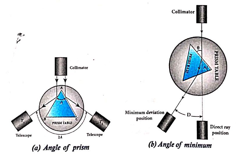
i) Angle of the prism (A):
(i) The prism is placed on the prism table with its refracting angle (A) facing the collimator as shown in Figure (a).
(ii) The slit is illuminated by sodium light (monochromatic light)
(iii)The parallel rays coming from the collimator fall on the two faces AB and AC and get reflected.
(iv) The telescope is rotated to the position T1 and T2 to capture the reflected rays and the two reading are noted
(v) The difference between these two readings gives the angle rotated by the telescope, which is twice the angle of the prism.
(vi) Half of this value gives the angle of the prism A.
ii) Angle of minimum deviation (D):
(i) The prism is placed on the prism table so that the light from the collimator falls on a refracting face, and the refracted image is observed through the telescope as shown in Figure.
(ii) The prism table is now rotated so that the angle of deviation decreases.
(iii) A stage comes when the image stops and returns on further rotation of the prism table.
(iv) This is ensured by looking through the telescope simultaneously. The reading in this position gives the minimum deviation position.
(v) Now, the prism is removed and the telescope is turned to receive the direct ray and the reading is noted.
(vi) The difference between the two readings gives the angle of minimum deviation D.
(vii) The refractive index of the material of the prism n is calculated using the formula,
\(\\ n=\cfrac { sin\left( \frac { A+D }{ 2 } \right) }{ sin\left( \frac { A }{ 2 } \right) } \) ..................(1)
The refractive index of a liquid may be determined in the same way using a hollow glass prism filled with the given liquid.
4.
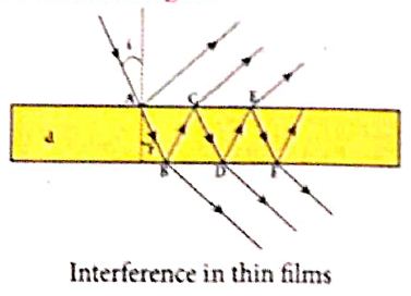
For transmitted light :
(i) The light transmitted may interfere to produce a resultant intensity. Consider the path difference between the two light waves transmitted from B and D.
(ii) The two waves moved together and remained in phase up to B where splitting occurred.
The extra path travelled by the wave transmitted from D is the path inside the film, BC + CD.
(iii) If we approximate the incidence to be nearly normal (i = 0), then the points B and D are very close to each other.
(iv) The extra distance travelled by the wave is approximately twice thickness of the film, BC + CD = 2d. As this extra path is traversed inside the medium of refractive index m, the optical path difference is, d = 2μd.
(v) The condition for constructive interference in transmitted ray is,
\(2\mu d=n\lambda \) .....(1)
(vi) Similarly, the condition for destructive interference in transmitted ray is,
\(2\mu d=\left( 2n-1 \right) \cfrac { \lambda }{ 2 } \) .....(2)
For reflected light:
(i) It is experimentally and theoretically proved that a wave while travelling in a rarer medium and getting reflected by a denser medium, undergoes a phase change of π.
(ii) Hence, an additional path difference of \(\cfrac { \lambda }{ 2 } \) should be considered for reflected light.
(iii) Let us consider the 2 path difference between the light waves reflected by the upper surface at A and the other wave coming out at C after passing through the film.
(iv) The additional path travelled by wave coming out from C is the path inside the film, AB + BC. For nearly normal incidence this distance could be approximated as, AB + BC = 2d.
(v) As this extra path is travelled in the medium of refractive index μ, the optical path difference is, ઠ = 2μd.
(vi)The condition for constructive interference for reflected ray is,
\(2\mu d+\cfrac { \lambda }{ 2 } =n\lambda \) (or) \(2\mu d=\left( 2n-1 \right) \cfrac { \lambda }{ 2 } \) .....(3)
(vii) The additional path difference \(\cfrac { \lambda }{ 2 } \) is due to the phase change of π in rarer to denser reflection taking place at A.
(viii) The condition for destructive interference for reflected ray is
\(2\mu d+\cfrac { \lambda }{ 2 } =\left( 2N+1 \right) \cfrac { \lambda }{ 2 } \) (or) \(2\mu d=n\lambda \) ....(4)
5.
Experimental setup:
(i) S is a source s1 and s2 the double slits which are at equidistances from 's'. Wavefronts from s1 and s2 spread out and overlap on other side of double slit.
(ii) When a screen is placed at a distance of about 1 meter from the slits, alternate bright and dark fringes which are equally spaced appear on the screen. These are called interference fringes or bands.
(iii) Using an eyepiece the fringes can be seen directly. At the center point O on the screen, waves from s1 and s2 travel equal distances and arrive in-phase as shown in Figure.
(iv) These two waves constructively interfere and bright fringe is observed at O. This is called cental bright fringe.
(v) When one of the slits is closed, The fringes disappear and there in uniform illumination on the screen.
(vi) This shows clearly that the bands are due to interference.
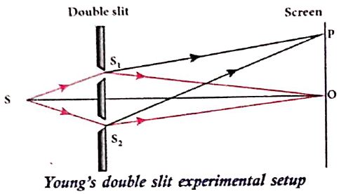
Equation for path difference :
(i) The Let d be the distance between the double slits s1 and s2 which act as coherent sources of wavelength λ.
(ii) A screen is placed parallel to the double slit at a distance D from it.
(iii) P is any point at a distance y from O.
(iv) The waves from S1 and S2 meet at P either in-phase or out-of-phase depending upon the path difference between the two waves.
.JPG)
The path difference \(\delta\) between the light waves from s1 and s2 to the point p is,
\(\delta=\mathrm{S}_{2} \mathrm{P}-\mathrm{S}_{1} \mathrm{P}\)
\(\delta=\mathrm{S}_{2} \mathrm{P}-\mathrm{MP}=\mathrm{S}_{2} \mathrm{M}\) .........(1)
\(\angle \mathrm{OCP}=\angle \mathrm{S}_{2} \mathrm{~S}_{1} \mathrm{M}=\theta\)
In right angle triangle \(\Delta \mathrm{S}_{1} \mathrm{S}_{2} \mathrm{M}\), the path difference S2M = d sin \(\theta\)
\(\delta=d \sin \theta\) ...........(2)
If the angle \(\theta\) is small, \(\sin \theta \approx \tan \theta \approx \theta\)
From the right angle triangle \(\Delta \mathrm{OCP}, \tan \theta=\frac{\mathrm{y}}{\mathrm{D}}\)
The path differences \(\delta=\frac{d y}{D}\) ...........(3)
Based on the condition of the path difference, the point P may have a bright (or) dark fringe
6.
Let us Consider two light waves from the two sources SI and S2 meeting at a point P as shown in figure
The wave from SI at an instant t at P is,
y1= a1 sin ω t ...................(1)
The wave form S2 at an instant t at P is,
y2= a2 sin (ωt + Φ) .............(2)
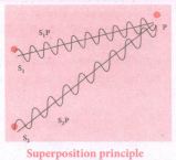
The two waves have different amplitudes al and a2 , same angular frequency ω, and a phase difference of \(\phi\)
y = y1 + y2 = a1 = a\sin ωt + a1sin2 (ωt + Φ) ............(3)
The simplification of the above equation by using trigonometric identities,
\(y=Asin\left( \omega t+\theta \right) \) ..............(4)
where, \(A=\sqrt { { a }_{ 1 }^{ 2 }+{ a }_{ 2 }^{ 2 }+2{ a }_{ 1 }{ a }_{ 2 }cos\phi } \) ..................(5)
\(\theta ={ tan }^{ -1 }\cfrac { { a }_{ 2 }sin\phi }{ { a }_{ 1 }+{ a }_{ 2 }cos\phi } \) ..................(6)
The resultant amplitude is maximum,
\({ A }_{ max }=\sqrt { \left( { a }_{ 1 }+{ a }_{ 2 } \right) ^{ 2 } } \) ; When Φ = 0,± 2π , ± 4π... ................(7)
The resultant amplitude is minimum
\({ A }_{ min }=\sqrt { \left( { a }_{ 1 }+{ a }_{ 2 } \right) ^{ 2 } } \); When Φ = ±π, ± 3π, ± 5π..., ............(8)
The intensity of light is proportional to square of amplitude,
I ∝ A2 ...........(9)
Now, equation (5) becomes,
\(1\infty { I }_{ 1 }+I_{ 2 }+2\sqrt { { I }_{ 1 }{ { I }_{ 2 } } } cos\phi \) ..........(10)
In equation (10) if the phase difference, f = 0, ± 2π, ± 4π ... , it corresponds to the condition for maximum intensity of light called as constructive interference.
The resultant maximum intensity is
\({ I }_{ max }\propto \left( { a }_{ 1 }+{ a }_{ 2 } \right) ^{ 2 }\propto { I }_{ 1 }{ I }_{ 2 }+2\sqrt { { \quad I }_{ 1 }{ I }_{ 2 } } \) ...............(11)
In equation (10) if the phase difference, Φ = ±π, ±3π, ± 5π ... , it corresponds to the condition for minimum intensity of light called destructive interference.
The resultant minimum intensity is,
\({ I }_{ min }\propto \left( { a }_{ 1 }+{ a }_{ 2 } \right) \propto { I }_{ 1 }+{ I }_{ 2 }2\sqrt { { I }_{ 1 }{ I }_{ 2 } } \) ................(12)
As a special case, if a1 = a2 = a, then equation (5) becomes
\(A=\sqrt{2 a^{2}+2 a^{2} \cos \phi} =\sqrt{2 a^{2}(1+\cos \theta)} \)
\(=\sqrt{2 a^{2} 2 \cos ^{2}\left(\frac{\phi}{2}\right)} \)
\(\mathrm{A}=2 \mathrm{a} \cos (\phi / 2) \) ........(13)
\(\mathrm{I} \alpha 4 \mathrm{a}^{2} \cos ^{2}(\phi / 2)\left[\therefore \mathrm{I} \alpha \mathrm{A}^{2}\right] \) ..............(14)
\(\mathrm{I}=4 \mathrm{I}_{0} \cos ^{2}(\phi / 2)\left[\therefore \mathrm{I}_{0} \alpha \mathrm{a}^{2}\right] \) ...............(15)
\(\mathrm{I}_{\max }=4 \mathrm{I}_{0} \text { when, } \phi=0, \pm 2 \pi, \pm 4 \pi \ldots . \) ...............(16)
\(\mathrm{I}_{\min }=0 \text { when, } \phi=\pm \pi, \pm 3 \pi, \pm 5 \pi \ldots . \) .............(17)
7.
Given, focal length of first lens, f1 = –70 cm,
focal length of second lens, f2 = 150 cm.
Equation for focal length of lenses in contact, \(\cfrac { 1 }{ f } =\cfrac { 1 }{ { f }_{ 1 } } +\cfrac { 1 }{ { f }_{ 2 } } \)
Substituting the values,
\(\cfrac { 1 }{ f } =\cfrac { 1 }{ -70 } +\cfrac { 1 }{ 150 } =\cfrac { 1 }{ 70 } +\cfrac { 1 }{ 150 } \)
\(\cfrac { 1 }{ f } =\cfrac { -150+70 }{ 70\times 150 } =\cfrac { -80 }{ 70\times 150 } =\cfrac { 80 }{ 10500 } \)
\(f=\cfrac { -1050 }{ 8 } =131.25cm\)
As the focal length is negative, the combination of two lenses is a diverging system of lenses
The power of the combination is,
\(P=\cfrac { 1 }{ f } =\cfrac { 1 }{ -1.3125m } =0.76D\)
8.
For a biconvex lens, radius of curvature of the first surface is positive and that of the second surface is negative as shown in the figure.
.JPG)
Given, n = 1.5, R1 = 20 cm and R2 = –15 cm
(a) Lensmaker’s formula \(\frac{1}{f}=(n-1)\left(\frac{1}{R_{1}}-\frac{1}{R_{2}}\right)\)
Substituting the values,
\(\frac{1}{f}=(1.5-1)\left(\frac{1}{20}-\frac{1}{-15}\right)=(1.5-1)\left(\frac{1}{20}+\frac{1}{15}\right)\)
\(\frac{1}{f}=(0.5)\left(\frac{1}{20}+\frac{1}{15}\right)=(0.5)\left(\frac{3+4}{60}\right)=\left(\frac{1}{2} \times \frac{7}{60}\right)=\frac{7}{120}\)
\(f=\frac{120}{7}\) = 17.14 cm
As the focal length is positive the lens is a converging lens.
(b) When the lens is flipped by the side,
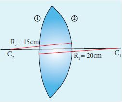
Now, R1= 15 cm and R2 = –20 cm, n = 1.5
Substituting the values in the lens maker's formula,
\(\cfrac { 1 }{ f } =\left( 1.5-1 \right) \left( \cfrac { 1 }{ 15 } -\cfrac { 1 }{-20 } \right) \)
\(\cfrac { 1 }{ f } =\left( 1.5-1 \right) \left( \cfrac { 1 }{ 15 } +\cfrac { 1 }{ 20 } \right) \)
This will also result in, f = 17.14 cm
Thus, it is concluded that the focal length of the lens will not change if it is flipped by the side. This is true for any lens. Students can verify this for any kind of lens.
9.
Given, thickness of the slab, t = 0.25 m, refractive index, n = 1.5, angle of incidence, i = 60o.
Using Snell’s law, 1 sin i = n sin r
\(sinr=\cfrac { sini }{ n } =\cfrac { sin60^o }{ 1.5 } =0.58\)
\(r={ sin }^{ -1 }(0.58)=35.25^{ 0 }=35^o15'0''\)
Lateral displacement is, \(L=t\left( \cfrac { sin\left( i-r \right) }{ cos\left( r \right) } \right) \)
\(L=\left( 0.25 \right) \times \left( \cfrac { sin\left( 60-35.25 \right) }{ cos\left( 35.25 \right) } \right) =0.1281m\)
The lateral displacement is, L = 12.81 cm
10.
(i) An astronomic telescope used to get the magnification of distant astronomical objects like stars, planets, moon etc.
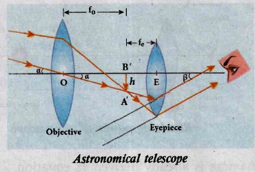
(ii) The image formed by astronomicaltelescope willbe inverted. It has an objective of long focal length and a much larger aperture than the eyepiece as shown in Figure.
(iii) Light from a distant object enters the objective and a real image is formed in the tube at its second focal point.
(iv) The eyepiece magnifies this image producing a final inverted image.
Magnification of astronomical telescope:
The magnification m is the ratio of the angle β subtended by the image to the angle α which subtended by the object with the principal axis
\(m=\cfrac { \beta }{ \alpha } \) ......(1)
From the diagram, ,\(\alpha=\frac{h}{f_e} \ and \ \beta=\frac{h}{f_e}\) ...................(2)
\(m=\cfrac { { f }_{ 0 } }{ { f }_{ e } } \) .........................(3)
The length of the telescope is approximate, L = f0 + fe.
11.
(i) A microscope is used to see the details of the object under observation.'
(ii) The ability of microscope depends not only on magnifying the object but also on resolving two points on the object separated by a small distance d .. nun
(iii) Smaller the value of dmin better will be the resolving power of the microscope.
(iv) The radius of central maxima is already derived as equation (1),
\(N=\cfrac { 1 }{ a+b } \)
\({ r }_{ 0 }=\cfrac { 1.22\lambda f }{ a } \)
(v) In the place of focal length f we have the image distance v. If the difference between the two points on the object to be resolved is dmin, then the magnification m is
\(m=\cfrac { { r }_{ 0 } }{ d_{ min } } \)
\({ d }_{ min }=\cfrac { { 1.22 }\lambda v }{ m } =\cfrac { 1.22\lambda v }{ a\left( \cfrac { v }{ u } \right) } =\cfrac { 1.22 }{ \lambda v } =\cfrac { 1.22\lambda u }{ a } \) \(\left[ \therefore m=\cfrac { v }{ u } \right] \)
\({ d }_{ min }=\cfrac { 1.22\lambda f }{ a } \) \(\left[ \therefore u=f \right] \)
On the object side,
\(2tan\beta =2sin\beta =\cfrac { a }{ f } \) \(\left[ \therefore a=f2sin\beta \right] \)
\({ d }_{ min }=\cfrac { 1.22\lambda }{ 2sin\beta } \)
(vi) To reduce the value of dmin the optical path of the light is increased by immersing the objective of the microscope into a bath containing oil of refractive index n.
12.
Since, the prism is equilateral, A = 60o;
Given, i1 = 30o;i2 = 75o
Equation for angle of deviation, d = i1 + i2 – A
Substituting the values, d = 30°+ 75°– 60°= 45°
The angle of deviation produced d = 45o
13.
Given, n1 = 1.68, n2 = 1.44, n3 = 1
Acceptance angle, \(\\ { i }_{ a }={ sin }^{ -1 }\left( \sqrt { { n }_{ 1 }^{ 2 }-{ n }_{ 2 }^{ 2 } } \right) \)
\({ i }_{ a }={ sin }^{ -1 }\left( \sqrt { \left( 1.68 \right)^2 -\left( 1.44 \right) ^{ 2 } } \right) ={ sin }^{ -1 }\left( 0.865 \right) \)
\({ i }_{ a }\simeq { 60 }^{ o }\)
If there is no cladding then, n2 = 1
Acceptance angle, \({ i }_{ a }={ sin }^{ -1 }\left( \sqrt { { n }_{ 1 }^{ 2 }-1 } \right) \)
\({ i }_{ a }={ sin }^{ -1 }\left( \sqrt { \left( 1.68 \right) ^{ 2 }-1 } \right) ={ sin }^{ -1 }\left( 1.35 \right) \)
sin−1(more than 1) is not possible. But, this includes the range 0o to 90o. Hence, all the rays entering the core from flat surface will undergo total internal reflection.
Note: If there is no cladding then there is a condition on the refractive index (n1) of the core
\({ i }_{ a }={ sin }^{ -1 }\left( \sqrt { { n }_{ 1 }^{ 2 }-1 } \right) \)
Here, as per mathematical rule,
\(\left( { n }_{ 1 }^{ 2 }-1 \right) \le 1\) or \(\left( { n }_{ 1 }^{ 2 } \right) \le 2\) or \({ n }_{ 1 }\le \sqrt { 2 } \)
Hence, in air (no cladding) the refractive index n1 of the core should be,\({ n }_{ 1 }\le 1.414\)
14.
When seen from (air medium) on top, the coin will still appear to be at the bottom with each medium appearing to have shrunk with respect to the air medium outside. This situation is illustrated below.
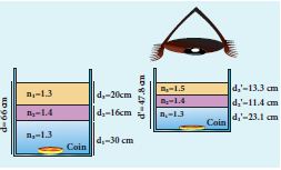
The equations for apparent depth for each medium is,
\({ d' }_{ 1 }=\cfrac { { d }_{ 1 } }{ { n }_{ 1 } } ;{ d }_{ 2 }^{ ' }=\cfrac { { d }_{ 2 } }{ { n }_{ 2 } } ;{ d }_{ 3 }^{ ' }=\cfrac { { d }_{ 3 } }{ { n }_{ 3 } } \)
\({ d }^{ ' }={ d }_{ 1 }^{ ' }+{ d }_{ 2 }^{ ' }+{ d }_{ 3 }^{ ' }=\cfrac { { d }_{ 1 } }{ n_{ 1 } } +\cfrac { { d }_{ 2 } }{ { n }_{ 2 } } +\cfrac { { d }_{ 3 } }{ n_{ 3 } } \)
\(d'=\cfrac { 30 }{ 1.3 } +\cfrac { 1.6 }{ 1.4 } +\cfrac { 30 }{ 1.5 } =23.1+11.4+13.3\)
d' = 47.8 cm
15.
Given, ngo = 1.25 and ng = 1.5
Refractive index of glass with respect to oil,
\({ n }_{ go }=\cfrac { { n }_{ g } }{ { n }_{ 0 } } \)
Rewriting for refractive index of oil,
\({ n }_{ p }=\cfrac { { n }_{ g } }{ { n }_{ go } } =\cfrac { 1.5 }{ 1.25 } =1.2\)
The refractive index of oil is, no = 1.2

12th Standard Syllabus & Materials
12th Standard
TN 12th Computer Applications களப்பெயர் முறைமை (DNS) Sample Question Papers Study Material - QB365 Set A
NEW12th Standard
TN 12th Computer Applications வலையமைப்பு எடுத்துக்காட்டுகள் மற்றும் நெறிமுறைகள் Sample Question Papers Study Material - QB365 Set A
NEW12th Standard
TN 12th Computer Applications கணினி வலையமைப்பு ஓர் அறிமுகம் Sample Question Papers Study Material - QB365 Set A
NEW12th Standard
TN 12th Computer Applications PHP-உடன் MySQL-ஐ இணைத்தல் Sample Question Papers Study Material - QB365 Set A



Tamilnadu Stateboard 12th Standard Subjects

Maths

Chemistry
Physics

Biology

Computer Science

Business Maths and Statistics

Economics

Commerce

Accountancy

History

Computer Applications
Biology
Computer Technology
Computer Applications
Computer Science
Business Maths and Statistics
Commerce
Economics
Maths
Chemistry
Physics
Computer Technology
History
Accountancy

Tamil

English

French
Tamilnadu Stateboard Standards

