
 100% FREE ACCESS
12th Standard Syllabus & Materials
12th Standard
TN 12th Computer Applications மின்னணு தரவு பரிமாற்றம் Sample Question Papers Study Material - QB365 Set A
NEW12th Standard
TN 12th Computer Applications மின் - வணிக பாதுகாப்பு அமைப்புகள் Sample Question Papers Study Material - QB365 Set A
NEW12th Standard
TN 12th Computer Applications மின்னணு செலுத்தல் முறைகள் Sample Question Papers Study Material - QB365 Set A
NEW12th Standard
TN 12th Computer Applications மின் - வணிகம் Sample Question Papers Study Material - QB365 Set A
NEW12th Standard
TN 12th Computer Applications திறந்த மூல கருத்துருக்கள் Sample Question Papers Study Material - QB365 Set A
NEW12th Standard
TN 12th Computer Applications வலையமைப்பு வடமிடல் Sample Question Papers Study Material - QB365 Set A

Published on: 13/09/2019
Download Tamil Nadu 12th Standard Physics question papers, model tests, one-mark questions, important questions, and public exam papers in PDF format. Free study materials and answer keys for TN State Board students.
Questions + Answers key
Take MCQ Physics Test1.
What is meant by dielectric breakdown?
2.
Mention the ways of producing induced emf.
3.
What is meant by Fraunhofer lines?
4.
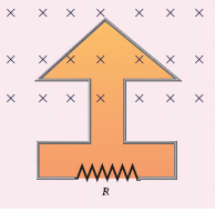
The magnetic flux passes perpendicular to the plane of the circuit and is directed into the paper. If the magnetic flux varies with respect to time as per the following relation \(\Phi_B\) = (2t3 + 3t2 + 8t + 5)mWb, what is the magnitude of the induced emf in the loop when t = 3 s? Find out the direction of current through the circuit.
5.
Write the general definition of electric dipole moment for a collection of point charge.
6.
State Joule’s law of heating.
7.
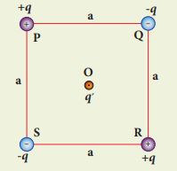
Four charges are arranged at the corners of the square PQRS of side an as shown in the figure.
(a) Find the work required to assemble these charges in the given configuration.
(b) Suppose a charge q is brought to the center of the square, by keeping the four charges fixed at the corners, how much extra work is required for this?
8.
What is electric power and electric energy?
9.
Thermo electric generators are used in power plants to convert_________ into electricity.
light energy
waste heat
sound energy
hydro energy
10.
Electric field intensity and electric potential are related by_________.
E = -\(\frac{dV}{dt}\)
E = -\(\frac{dV}{dx}\)
E = \(\frac{dV}{dt}\)
E = \(\frac{-dx}{dV}\)
11.
Two identical resistors are connected in parallel then connected in series. The effective resistance are in the ratio ________________.
1:2
2:1
1:4
4:1
12.
Relative permittivity (εr) is also known as ________
dielectric strength
dielectric constant
polarisability
susceptibility
13.
Temperature co-effieient of resistance for metals is ______________.
constant
positive
zero
negative
14.
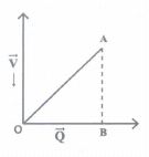
Charge Q on a capacitor varies with voltage V as shown in graph, where Q is along X-axis and V along Y-axis. The area of triangle OAB represents
capacitance
capacitive reactance
magnetic field between the plates
energy stored in the capacitor
15.
Which of the following statement on equipotential surface is wrong?
The potential difference between any two points on the surface, is zero.
The electric field is always perpendicular to the surface
Equipotential surface is always spherical.
No work is done in moving a charge along the surface
16.
The magnitude of electric dipole moment of water molecule is
6 x 10-30 cm
6.2 x 10⁻³⁰ cm
6.1 x 10⁻³⁰
5.95 10-30 cm
17.
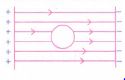
An uncharged metal sphere is placed between two equal and oppositely charged metal plates. The nature of lines of force will be ______________
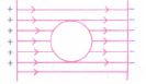
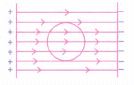
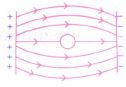
18.
A thin insulated wire forms a plane spiral of N = 100 tight turns carrying a current I = 8 m A (milli ampere). The radii of inside and outside turns are a = 50 mm and b = 100 mm respectively. The magnetic induction at the centre of the spiral is ______.
\(5\mu T\)
\(7\mu T\)
\(8\mu T\)
\(10\mu T\)
19.
When the current changes from +2A to −2A in 0.05 s, an emf of 8 V is induced in a coil. The co-efficient of self-induction of the coil is
0.2H
0.4H
0.8H
0.1H
20.
Which one of them is used to produce a propagating electromagnetic wave?
an accelerating charge
a charge moving at constant velocity
a stationary charge
an uncharged particle
21.
An electric field \(\vec { E } =10x\hat { i } \) exists in a certain region of space. Then the potential difference V = Vo – VA, where Vo is the potential at the origin and VA is the potential at x = 2 m is _____.
10 V
-20 V
+20 V
-10 V
22.
Two identical point charges of magnitude –q are fixed as shown in the figure below. A third charge +q is placed midway between the two charges at the point P. Suppose this charge +q is displaced a small distance from the point P in the directions indicated by the arrows, in which direction(s) will +q be stable with respect to the displacement?
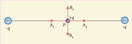
A1 and A2
B1 and B2
both directions
No stable
23.
Two wires of A and B with circular cross section made up of the same material with equal lengths. Suppose RA = 3 RB, then what is the ratio of radius of wire A to that of B?
3
\(\sqrt3\)
\(\frac{1}{\sqrt3}\)
\(\frac{1}{3}\)
24.
A toroidal solenoid with air core has an average radius of 15cm, area of cross section 12cm2 and has 2000 turns. Calculate the self- inductance of the toroid. Assume the field to be uniform across the cross-section of the toroid.
25.
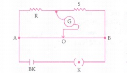
In a meter bridge, the balancing length is found to be 40 cm from end A. If the resistance of 10 \(\Omega \) is connected in series with R, balancing length is obtained 60 em from A. calculate the value R & S.
26.
Calculate the potential at a point P due to charge of 5 x 10⁻⁷Clocated 11cm away.
27.
Three points A, B & C lie in a uniform electric field (E) of 5 x 10³ NC-1 Find the potential difference between A & C.
28.
Explain the working of a single-phase AC generator with necessary diagram.
29.
Tabulate the difference between Coulomb's law and Biot-Savort's law.
30.
How does the capacitive reactance depend on frequency? & What is the reactance of a capacitor at hertz to the study at?
31.
What are carbon resistors? What does the colour indicates?
32.
Derive the expressions for the potential energy of a system of point charges.
1.
When the external electric field applied to a dielectric is very large, it tears the atoms apart so that the bound charges become free charges. Then the dielectric starts to conduct electricity. This is called dielectric breakdown.
2.
Emf can be produced by changing magnetic flux in any of the following ways:
(i) By changing the magnetic field B
(ii) By changing the area A of the coil and
(iii) By changing the relative orientation θ of the coil with magnetic field.
3.
When the spectrum obtained from the Sun is examined, it consists of large number of dark lines (line absorption spectrum). These dark lines in the solar spectrum are known as Fraunhofer lines.
4.
\(\Phi_B\) = (2t3 + 3t2 + 8t + 5)mWb; N = 1;t = 3 s
i) \(ε=\frac { d(N{ \Phi }_{ B }) }{ dt } \)
\(=\frac { d }{ t } \left( { 2t }^{ 3 }+{ 3t }^{ 2 }+8t+5 \right) \times { 10 }^{ -3 }\)
= (6t2 + 6t + 8) x 10-3 V
At t = 3 s,
ε = [( 6 x 9) + (6 x 3) + 8] x 10-3
= 80 x 10-3V = 80mV
(ii) As time passes, the magnetic flux linked with the loop increases. According to Lenz’s law, the direction of the induced current should be in a way so as to oppose the flux increase. So, the induced current flows in such a way to produce a magnetic field opposite to the given field. This magnetic field is perpendicularly outwards. Therefore, the induced current flows in anticlockwise direction.
5.
For a collection of n point charges, the electric dipole moment is defined as follows, \(\vec{p}=\stackrel{i=n} \sum _{i=1}q_i\vec{r}_i\) where, \(\vec{r}_i\) is the position vector of charge qi from the origin.
6.
It states that the heat developed in an electrical circuit due to the flow of current varies directly as
(i) the square of the current
(ii) the resistance of the circuit and
(iii) the time of flow.
7.
(a) The work done to arrange the charges in the corners of the square is independent of the way they are arranged. We can follow any order.
(i) First, the charge +q is brought to the corner P. This requires no work since no charge is already present, WP = 0
(ii) Work required to bring the charge –q to the corner Q = (-q) x potential at a point Q due to +q located at a point P
WQ = -q x \(\frac { 1 }{ 4\pi { \varepsilon }_{ 0 } } \frac { q }{ a } =-\frac { 1 }{ 4\pi { \varepsilon }_{ 0 } } \frac { q^{ 2 } }{ a } \)
(iii) Work required to bring the charge +q to the corner R = q x potential at the point R due to charges at the point P and Q.
WR = q x \(\frac { 1 }{ 4\pi { \varepsilon }_{ 0 } } \left( -\frac { q }{ a } +\frac { q }{ \sqrt { 2 } a } \right) \)
= \(\frac { 1 }{ 4\pi { \varepsilon }_{ 0 } } \frac { { q }^{ 2 } }{ a } \left( -1+\frac { 1 }{ \sqrt { 2 } } \right) \)
(iv) Work required to bring the fourth charge –q at the position S = q × potential at the point S due the all the three charges at the point P, Q and R.
Ws = - q x \(\frac { 1 }{ 4\pi { \varepsilon }_{ 0 } } \left( \frac { q }{ a } +\frac { q }{ a } -\frac { q }{ \sqrt { 2 } a } \right) \)
Ws = \(-\frac { 1 }{ 4\pi { \varepsilon }_{ 0 } } \frac { q^2 }{ a } \left( 2-\frac { 1 }{ \sqrt { 2 } } \right) \)
(b) Work required to bring the charge q′ to the center of the square = q′ x potential at the center point O due to all the four charges in the four corners.
The potential created by the two +q charges are canceled by the potential created by the -q charges which are located in the opposite corners. Therefore the net electric potential at the center O due to all the charges in the corners is zero.
Hence no work is required to bring any charge to the point O. Physically this implies that if any charge q′ when brought close to O, then it moves to the point O without any external force.
8.
Electric power:
(i) The electric power P is the rate at which the electrical potential energy is delivered.
(ii) The electric power P is the rate at which the work is done.
\( P= \frac{d U}{d t} (or)= \frac{d W}{d t} (or)=VI(or)\frac{V^2}{R}\)
Unit: watt (W)
Electric energy:
(i) The electric energy is the product of power (P) and duration of the time (t) when electric energy is delivered.
(ii) E = Pt
Unit: watt-hour (Wh)
9.
(b)
waste heat
10.
(b)
E = -\(\frac{dV}{dx}\)
11.
(a)
1:2
12.
(b)
dielectric constant
13.
(b)
positive
14.
(d)
energy stored in the capacitor
15.
(a)
The potential difference between any two points on the surface, is zero.
16.
(c)
6.1 x 10⁻³⁰
17.
(b)
18.
(b)
\(7\mu T\)
19.
\(\text {emf } e=8 \mathrm{~V} \)
\(d I=I_1-I_0=2-(-2)=4 \mathrm{~A} \)
\(\text {dt }=0.05 \mathrm{~s} \)
\(L=\frac{-e}{d I / d t}=\frac{-8}{4 / 0.05} \)
\(=\frac{-8 \times 0.05}{4}=\frac{-0.40}{4} \)
=-0.1 H
-ve sign indicates that self-induced emf always opposes the current w.r.t. time.
20.
(a)
an accelerating charge
21.
\(\vec {E}\) = 10x\(\hat{i},\) when x = 2 m
\(\vec {E}\) = 10 x 2 x \(\hat{i}\) = 20\(\hat{i}\)
Since, \(E=\frac{-dV}{dx}\therefore V=+20 V\)
22.
The charge + q will be stable between B1 and B2 with respect to the displacement.
23.
\(R \propto \frac{1}{A}, R \propto \frac{1}{r^2} \)
\(R_A \propto \frac{1}{r_A^2}, R_B \propto \frac{1}{r_B^2} \)
\(\frac{r_A}{r_B}=\left(\frac{R_B}{R_A}\right)^{1 / 2}=\left(\frac{R_B}{3 R_B}\right)^{1 / 2}=\frac{1}{3^{\frac{1}{2}}}=\frac{1}{\sqrt{3}}\)
24.
Given: Radius of the toroid r = 15cm = 15 x 10-2 m
Area of the toroid A = 12cm2 = 12 x 10-4m
No. of turns N = 2000
To find:
Self inductance of the toroid L =?
Formula:
\(L=\frac { { \mu }_{ o }{ N }^{ 2 }{ A } }{ l } =\frac { { \mu }_{ o }{ { N }^{ 2 }A } }{ 2\pi r } \)
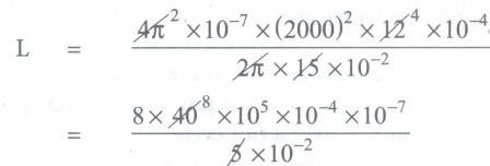
= 6.4 x 10⁻³ H (or) 6.4 MH
25.
According to Wheatstone bridge \(\cfrac { P }{ Q } =\cfrac { R }{ S } \)
\(\cfrac { R }{ S } =\cfrac { OA }{ OB } =\cfrac { 40 }{ 60 } \)
\(\cfrac { R }{ S } =\cfrac { OA }{ OB } =\cfrac { 40 }{ 60 } \)
If resistance 10 \(\Omega \) connected in series with R, the balance length is 60 cm.
\(\cfrac { R+10 }{ S } =\cfrac { 60 }{ 40 } \Rightarrow 2R+20=3S\)
From (1) & (2) \(\Rightarrow \left[ \cfrac { 4S }{ 3 } +20=3S \right] \)
45 + 60 = 95
55 = 60
\(S=\cfrac { 60 }{ 5 } =12\)
\(2\times \cfrac { 2S }{ 3 } +20=3S\)
\(s=12\Omega \)
From equation (1)
\(R=2\times \cfrac { 12 }{ 3 } =8\Omega \)
\(R=8\Omega \)
26.
\(V=\frac { q }{ 4\pi { \varepsilon }_{ 0 }r } \)
\(F=\frac { { q }_{ 1 }{ q }_{ 2 } }{ { r }^{ 2 } } \)
= 40.9kV
27.
The line joining B to C is perpendicular to electric field
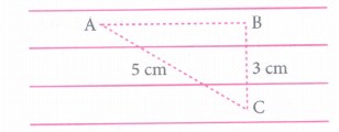
So potential of B = potential of C
i.e. VB = Vc
Distance AB = 4 cm
Potential difference
between A & C = E x AB
= 5 x 103 x (4 x 10-2)
= 200 volt.
AC2 = AB2 + B2
AB2 = AC2 - BC2
= 25 - 9 = 16
AB = 4cm
28.
.JPG)
Working: The loop PQRS is stationary and is perpendicular to the plane of the paper. When field windings are excited, magnetic field is produced around it. Let the field magnet be rotated in clockwise direction by some external means (Figure).
(i) Assume that initial position of the field magnet is horizontal. At that instant, the direction of magnetic field is perpendicular to the plane of the loop PQRS. The induced emf is zero. This is represented by origin O in the graph between induced emf and time angle.
(ii) When field magnet rotates through 90°, magnetic field becomes parallel to PQRS. The induced emfs across PQ and RS would become maximum. Since they are connected in series, emfs are added up and the direction of total induced emf is given by Flemin's right hand rule.
.JPG)
(iii) Care has to be taken while applying this rule, the thumb indicates the direction of the motion of the conductor with respect to field. For clockwise rotating poles, the conductor appears to be rotating anticlockwise. Hence, thumb should point to the left. The direction of the induced emf is at right angles to the plane of the paper. For PQ, it is inwards and for RS outwards. Therefore, the current flows along PQRS. The point A in the graph represents this maximum emf.
(iv) For the rotation of 180° from the initial position, the field is again perpendicular to PQRS and the induced emf becomes zero. This is represented by point B.
(v) The field magnet becomes again parallel to PQRS for 270° rotation of field magnet. The induced emf is maximum but the direction is reversed. Thus the current flows along SRQP. This is represented by point C
(vi) On completion of 360°, the induced emf becomes zero and is represented by the point D. From the graph, it is clear that emf induced in PQRS is alternating in nature.
(vii) Therefore, when field magnet completes one rotation, induced emf in PQRS finishes one cycle.
29.
| S.No | Electric field | Magnetic field |
| (i) | Produced by a scalar source i.e., an electric charge q | Produced by a vector source i.e., current element I\(\vec { dl } \) |
| (ii) | It is directed along the position vector joining the source and the point at which the field is calculated. | it is directed perpendicular to the position vector \(\hat { r } \) and the current element I\(\vec { dl } \) |
| (iii) | Does not depend on the angle | Depends on the angle between the position vector \(\hat { r } \) and the current element I\(\vec { dl } \) |
30.
Current leads the applied voltage by \(\frac{\pi}{2}\) in a capacitive circuit.
This is the resistance offered by the capacitor, called capacitive reactance (Xc). It measured in ohm.
\({ X }_{ c }=\frac { 1 }{ \omega C } \)
The capacitive reactance (Xc) varies inversely as the frequency. For a steady current, f = 0
∴\({ X }_{ c }=\frac { 1 }{ \omega C } -\frac { 1 }{ 2\pi fC } =\frac { 1 }{ 0 } =\infty \)
Thus a capacitive circuit offers infinite resistance to the steady current.
31.
(i) Carbon resistors consists of a ceramic core, on which a thin layer of crystalline Carbon is deposited. These resistors are inexpensive, stable and compact in size. Color rings are used to indicate the value of the resistance.
(ii) Three coloured rings are used to indicate the values of a resistor: the first two rings are significant figures of resistances, the third ring indicates the decimal multiplier after them. The fourth color, silver or gold shows the tolerance of the resistor.
| Color | Number | Multiplier | Tolerance |
|---|---|---|---|
| Black | 0 | 1 | - |
| Brown | 1 | 101 | - |
| Red | 2 | 102 | - |
| Orange | 3 | 103 | - |
| Yellow | 4 | 104 | - |
| Green | 5 | 105 | - |
| Blue | 6 | 105 | - |
| Violet | 7 | 107 | - |
| Gray | 8 | 107 | - |
| White | 9 | 109 | - |
| Gold | - | 10-1 | 5% |
| Slive | - | 10-2 | 10% |
| Colorless | - | - | 20% |
32.
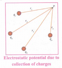
(i) The electric potential at a point P due to a collection of charges q1, q2, q3, ···qn is equal to sum of the electric potentials due to individual charges.
\({ V }_{ tot }=\frac { k{ q }_{ 1 } }{ { r }_{ 1 } } +\frac { { kq }_{ 2 } }{ { r }_{ 2 } } +\frac { { kq }_{ 3 } }{ { r }_{ 3 } } +...\frac { { kq }_{ n } }{ { r }_{ n } } =\frac { 1 }{ 4\pi { \varepsilon }_{ 0 } } { \sum { } }_{ i=1 }^{ n }\frac { { q }_{ i } }{ { r }_{ i } } \)
(ii) where r1, r2, r3 .... rn are the distances of q1, q2, q3 ..... qn respectively from P(Figure).

12th Standard Syllabus & Materials
12th Standard
TN 12th Computer Applications களப்பெயர் முறைமை (DNS) Sample Question Papers Study Material - QB365 Set A
NEW12th Standard
TN 12th Computer Applications வலையமைப்பு எடுத்துக்காட்டுகள் மற்றும் நெறிமுறைகள் Sample Question Papers Study Material - QB365 Set A
NEW12th Standard
TN 12th Computer Applications கணினி வலையமைப்பு ஓர் அறிமுகம் Sample Question Papers Study Material - QB365 Set A
NEW12th Standard
TN 12th Computer Applications PHP-உடன் MySQL-ஐ இணைத்தல் Sample Question Papers Study Material - QB365 Set A



Tamilnadu Stateboard 12th Standard Subjects

Maths

Chemistry
Physics

Biology

Computer Science

Business Maths and Statistics

Economics

Commerce

Accountancy

History

Computer Applications
Biology
Computer Technology
Computer Applications
Computer Science
Business Maths and Statistics
Commerce
Economics
Maths
Chemistry
Physics
Computer Technology
History
Accountancy

Tamil

English

French
Tamilnadu Stateboard Standards

