
 100% FREE ACCESS
12th Standard Syllabus & Materials
12th Standard
TN 12th Maths Applications of Matrices and Determinants Sample Question Papers Study Material - QB365 Set A
NEW12th Standard
TN 12th Computer Applications மின்னணு தரவு பரிமாற்றம் Sample Question Papers Study Material - QB365 Set A
NEW12th Standard
TN 12th Computer Applications மின் - வணிக பாதுகாப்பு அமைப்புகள் Sample Question Papers Study Material - QB365 Set A
NEW12th Standard
TN 12th Computer Applications மின்னணு செலுத்தல் முறைகள் Sample Question Papers Study Material - QB365 Set A
NEW12th Standard
TN 12th Computer Applications மின் - வணிகம் Sample Question Papers Study Material - QB365 Set A
NEW12th Standard
TN 12th Computer Applications திறந்த மூல கருத்துருக்கள் Sample Question Papers Study Material - QB365 Set A

Published on: 27/02/2021
12th Standard English Medium Physics Reduced syllabus Three mark important Questions with Answer key - 2021(Public Exam )
Download Tamil Nadu 12th Standard Physics question papers, model tests, one-mark questions, important questions, and public exam papers in PDF format. Free study materials and answer keys for TN State Board students.
Questions + Answers key
Take MCQ Physics Test1.
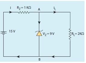
Find the current through the Zener diode when the load resistance is 2 kΩ. Use diode approximation.
2.
Discuss the beta decay process with examples.
3.
Magnetic field lines can be entirely confined within the core of toroid, but not within a straight solenoid. Why?
4.
Define potential difference and derive.
5.
Compare the electromagnetic oscillations of LC circuit with the mechanical oscillations of blockspring system qualitatively to find the expression for angular frequency of LC oscillator.
6.
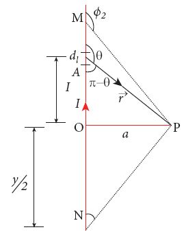
Calculate the magnetic field at a point P which is perpendicular bisector to current carrying straight wire as shown in figure.
7.
8.
Obtain the expression for energy stored in the parallel plate capacitor.
9.
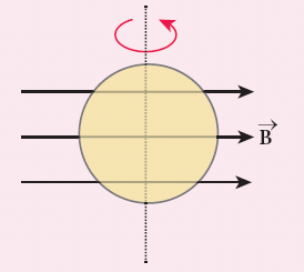
A circular loop of area 5 x 10⁻² m2 rotates in a uniform magnetic field of 0.2T. If the loop rotates about its diameter which is perpendicular to the magnetic field as shown in figure. Find the magnetic flux linked with the loop when its plane is
(i) normal to the field
(ii) inclined 60o to the field and
(iii) parallel to the field.
10.
A short bar magnet has a magnetic moment of 0.5 J T–1. Calculate magnitude and direction of the magnetic field produced by the bar magnet which is kept at a distance of 0.1 m from the centre of the bar magnet along
(a) axial line of the bar magnet and
(b) normal bisector of the bar magnet.
11.
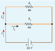
Calculate the equivalent resistance in the following circuit and also find the values of current I, I1 and I2 in the given circuit.
12.
Calculate the electrostatic force and gravitational force between the proton and the electron in a hydrogen atom. They are separated by a distance of 5.3 x 10⁻¹¹ m. The magnitude of charges on the electron and proton are 1.6 x 10⁻¹⁹ C. Mass of the electron is me = 9.1 x 10⁻³¹ kg and mass of proton is mp = 1.6 x 10⁻²⁷ kg.
13.
A monochromatic light is incident on an equilateral prism at an angle 30o and is emergent at an angle of 75o . What is the angle of deviation produced by the prism?
14.
Light travelling through transparent oil enters in to glass of refractive index 1.5. If the refractive index of glass with respect to the oil is 1.25, what is the refractive index of the oil?
15.
The self-inductance of an air-core solenoid is 4.8 mH. If its core is replaced by iron core, then its self-inductance becomes 1.8 H. Find out the relative permeability of iron.
16.
A sample of HCl gas is placed in a uniform electric field of magnitude 3 x 10⁴ NC-1. The dipole moment of each HCl molecule is 3.4 x 10⁻³⁰ Cm. Calculate the maximum torque experienced by each HCl molecule.
17.
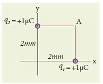
Consider the charge configuration as shown in the figure. Calculate the electric field at point A. If an electron is placed at points A, what is the acceleration experienced by this electron? (mass of the electron = 9.1 x 10⁻³¹ kg and charge of electron = −1.6 x 10⁻¹⁹ C)
18.
A copper wire of cross-sectional area 0.5 mm2 carries a current of 0.2 A. If the free electron density of copper is 8.4 x 1028 m-3 then compute the drift velocity of free electrons.
19.
Obtain the equation for resolving power of optical instruments.
20.
Obtain lens maker’s formula and mention its significance.
21.
Discuss the spectral series of hydrogen atom.
22.
Derive an expression for phase angle between the applied voltage and current in a series RLC circuit.
23.
Explain in detail how charges are distributed in a conductor, and the principle behind the lightning conductor.
24.
Explain the determination of unknown resistance using meter bridge.
25.
Obtain the macroscopic form of Ohm’s law from its microscopic form and discuss its limitation.
1.
Voltage across AB, is VZ = 9V
Voltage drop across Rs = 15 - 9 = 6V
Therefore current through the resistor Rs,
I = \(\frac { 6 }{ 1\times { 10 }^{ 3 } } \) = 6 mA
Voltage across the load resistor, = VAB = 9V
Current through load resistor,
\({ I }_{ L }=\frac { { V }_{ AB } }{ { R }_{ L } } =\frac { 9 }{ 2\times { 10 }^{ 3 } } =4.5mA\)
The current through the Zener diode,
IZ = I - IL = 6 mA - 4.5mA = 1.5 mA
2.
(i) In beta decay, a radioactive nucleus emits either electron or positron. If electron (e-) is emitted, it is called β- decay and if positron (e+) is emitted, it is called β- decay
(ii) The positron is an anti-particle of an electron whose mass is same as that of electron and charge is opposite to that of electron - that is, +e. Both positron and electron are referred to as beta particles.
β- decay:
(iii) β- decay: In β- decay, the atomic number of the nucleus increases by one but mass number remains the same. This decay is represented by
\(_{ Z }^{ A }{ X }\rightarrow _{ Z+1 }^{ A }{ Y+ }{ e }^{ - }+\bar { v } \) ...(1)
(iv) It implies that the element X becomes Y by giving out an electron and antineutrino (⊽).
(v) In other words, In each β- decay, one neutron (n) in the nucleus of X is converted into a proton(p) by emitting an electron (e-) and antineutrino(⊽). It is given by
\(n\rightarrow p+{ e }^{ - }+\bar { v } \)
Example :
\(_{ 6 }^{ 14 }{ C }\rightarrow _{ 7 }^{ 14 }{ N+ }{ e }^{ - }+\overline { v } \)
β+ decay:
(vi) In β+ decay, the atomic number is decreased by one and the mass number remains the same. This decay is represented by
\(_{ Z }^{ A }{ X }\rightarrow _{ Z-1 }^{ A }{ Y+ }{ e }^{ + }+v\)
(vii) It implies that the element X becomes Y by giving out an positron (e+) and neutrino (v),
In otherwords, in each β+ decay, one proton(p) in the nucleus of X is converted into a neutron by emitting a positron (e+) and a neutrino. It is given by
\(p\rightarrow n+{ e }^{ +}+{ v } \)
Example:
\(_{ 11 }^{ 22 }{ Na }\rightarrow _{ 10 }^{ 22 }{ Ne }+{ e }^{ + }+v\)
(viii) However a single proton (not inside any nucleus) cannot have β+ decay due to energy conservation, because neutron mass is larger than proton mass.
(ix) But a single neutron (not inside any nucleus) can have β- decay.
(x) It is important to note that the electron or positron which comes out from nuclei during beta decay never present inside the nuclei rather they are produced during the conversion of neutron into proton or proton into neutron inside the nucleus.
3.
Magnetic field lines can be entirely confined within the core of a toroid since the toroid has no ends. θ solenoid is open ended and the field lines inside it which are parallel to the length of the solenoid cannot form closed curves inside the solenoid.
4.
(i) The potential energy difference per unit charge is given by
\(\frac { \Delta U }{ q' } =\frac { q'\int _{ R }^{ P }{ (-\overset { \rightarrow }{ E } ) } .d\overset { \rightarrow }{ r } }{ q' } =\int _{ R }^{ P }{ \overset { \rightarrow }{ E } } .d\overset { \rightarrow }{ r } \quad ...(1)\)
(ii) The above equation (1) is independent of q'. The quantity \(\frac { \Delta U }{ q' } =\int _{ R }^{ P }{ \overset { \rightarrow }{ E } } .d\overset { \rightarrow }{ r } \) is called electric potential difference between P and R and is denoted as VP - VR = ∆V.
(iii) In other words the electric potential difference is also defined as the work done by an external force to bring unit positive charge from point R to point P.
\({ V }_{ p }-{ V }_{ R }=\Delta V=\int _{ R }^{ P }{ \overset { \rightarrow }{ E } } .d\overset { \rightarrow }{ r } \)
(iv) The electric potential energy difference can be written as ∆U = q' ∆V.
5.
Qualitative treatment:
The electromagnetic oscillations of LC system can be compared with the mechanical oscillations of a spring-mass system.
There are two forms of energy involved in LC oscillations. One is electrical energy of the charged capacitor, the other magnetic energy of the inductor carrying current.
Table: Energy in two oscillatory systems:
| LC oscillator | Spring-mass system | ||
| Element | Energy | Element | Energy |
| Capacitor | Electrical Energy \(=\frac{1}{2}\left(\frac{1}{\mathrm{C}}\right) q^{2}\) | Spring | Potential energy\(\frac{1}{2} k x^{2}\) |
| Inductor | Magnetic energy \(=\frac{1}{2} \mathrm{~Li}^2, i=\frac{dq}{dt}\) | Mass | Kinetic energy\(=\frac{1}{2} m v^{2},v=\frac{dx}{dt} \) |
Likewise, the mechanical energy of the spring-mass system exists in two forms; the potential energy of the compressed or extended spring and the kinetic energy of the mass. The Table lists these two pairs of energy.
By examining the table, the analogies between the various quantities can be understood and these correspondences are given in the Table.
The angular frequency of oscillations of a spring-mass is given by,
\(\omega= \sqrt \frac{k}{m}\)
From Table, k→ 1/C and m → L. Therefore, the angular frequency of LC oscillations is given by,
\(\omega= \frac{1} {\sqrt {LC}}\)
6.
Let the length MN = y and the point P is on its perpendicular bisector. Let O be the point on the conductor as shown in figure. Therefore,
\(OM=ON=\frac { y }{ 2 } ,then\)
\(cos\varphi _{ 1 }=\frac { \frac { y }{ 2 } }{ \sqrt { \frac { { y }^{ 2 } }{ 4 } +{ d }^{ 2 } } } =\frac { adjacent \ length }{ hypotenuse \ length } \)
\(=\frac { ON }{ PH } =-\frac { \frac { y }{ 2 } }{ \sqrt { \frac { { y }^{ 2 } }{ 4 } +{ a }^{ 2 } } } =-\frac { y }{ \sqrt { { y }^{ 2 }+{ 4a }^{ 2 } } } \)
\(cos\varphi _{ 1 }=\frac { adjacent \ length }{ hypotenuse \ length } =\frac { OM }{ PM } \)
\(=-\frac { \frac { y }{ 2 } }{ \sqrt { \frac { { y }^{ 2 } }{ 4 } +{ a }^{ 2 } } } =-\frac { y }{ \sqrt { { y }^{ 2 }+{ 4a }^{ 2 } } } \)
Hence,
\(\overset { \rightarrow }{ B } =\frac { { \mu }_{ ° }I }{ 4\pi a\sqrt { { y }^{ 2 }+{ 4a }^{ 2 } } } \hat { n } \)
For long straight wire, Y\(\rightarrow \infty ,\)
\(\overset { \rightarrow }{ B } =\frac { { \mu }_{ ° }I }{ 2\pi a } \hat { n } \)
The result obtained is the same as we obtained in equation (3.39).
7.
8.
Energy stored in the capacitor
i) Capacitor not only stores the charge but also it stores energy. When a battery is connected to the capacitor, electrons of total charge - Q are transferred from one plate to the other plate. To transfer the charge, work is done by the battery. This work done is stored as electrostatic potential energy in the capacitor.
ii) To transfer an infinitesimal charge dQ for a potential difference V, the work done is given by
dW = V dQ
Where \(V=\frac { Q }{ C } \) .....(1)
iii) The total work done to charge a capacitor is
\(W=\int _{ 0 }^{ Q }{ \frac { Q }{ C } } dQ=\frac { { Q }^{ 2 } }{ 2C } \quad \quad ....(2)\)
This work done is stored as electrostatic potential energy (UE) in the capacitor.
\({ U }_{ E }=\frac { { Q }^{ 2 } }{ 2C } =\frac { 1 }{ 2 } { CV }^{ 2 },\quad (\therefore Q=CV)\quad ....(3)\)
(iv) This stored energy is thus directly proportional to the capacitance of the capacitor and the square of the voltage between the plates of the capacitor.Substituting \(C=\frac { { \varepsilon }_{ 0 }A }{ d } \) and V = Ed.
\(U=\frac { 1 }{ 2 } \left( \frac { { \varepsilon }_{ 0 }A }{ d } \right) { (Ed) }^{ 2 }=\frac { 1 }{ 2 } { \varepsilon }_{ 0 }(Ad){ E }^{ 2 }\quad \quad \quad \quad \quad ...(4)\)
where Ad = volume of the space between the capacitor plates. The energy stored per unit volume of space is defined as energy density \({ u }_{ E }=\frac { U }{ Volume } \)
Equation (4) ⇒ \({ u }_{ E }=\frac{1}{2}{ \varepsilon }_{ 0 }{ E }^{ 2 }\).....(5)
(v) From equation (5),
(a) We infer that the energy is stored in the electric field existing between the plates of the capacitor. Once the capacitor is allowed to discharge, the energy is retrieved.
(b) The energy density depends only on the electric field and not on the size of the plates of the capacitor.
(c) This is true for the electric field due to any type of charge configuration.
9.
A = 5 x 10⁻² m2; B = 0.2 T
(i) θ = 0°;
\({ \Phi }_{ B }=BAcos\theta =0.2\times 5\times { 10 }^{ -2 }\times { cos }0^{ o }\)
\({ \Phi }_{ B }=1\times { 10 }^{ -2 }Wb\)
(ii) θ = 90° – 60° = 30°;
\(\Phi_B\) = BAcosθ = 0.2 x 5 x 10-2 x cos 30o
\({ \Phi }_{ B }=1\times { 10 }^{ -2 }\times \frac { \sqrt { 3 } }{ 2 } =8.66\times { 10 }^{ -3 }Wb\)
(iii) θ = 90°;
\({ \Phi }_{ B }\) = BA cos90o = 0
10.
Given magnetic moment 0.5 J T-1 and distance r = 0.1 m
(a) When the point lies on the axial line of the bar magnet, the magnetic field for short magnet is given by
\({ { \vec B }_{ axial } } =\frac { { \mu }_{ ° } }{ 4\pi } \left( \frac { 2{ p }_{ m } }{ { r }^{ 3 } } \right) \hat { i } \)
\({ { \vec B }_{ axial } } =1{ 0 }^{ -7 }\times \left( \frac { 2\times 0.5 }{ { \left( 0.1 \right) }^{ 3 } } \right) =1\times { 10 }^{ -4 }\hat { i } \ T\)
Hence, the magnitude of the magnetic field along axial is Baxial = 1 x 10⁻⁴ T and direction is towards South to North.
(b) When the point lies on the normal bisector (equatorial) line of the bar magnet, the magnetic field for short magnet is given by
\({ {\vec B }_{ equatorial } } =-\frac { { \mu }_{ ° } }{ 4\pi } \frac { { p }_{ m } }{ { r }^{ 3 } } \hat { i } \)
\({ {\vec B }_{ equatorial } } =-1{ 0 }^{ -7 }\left( \frac { 0.5 }{ { \left( 0.1 \right) }^{ 3 } } \right) \hat { i } =-0.5\times 1{ 0 }^{ -4 }\hat { i } \ T \)
Hence, the magnitude of the magnetic field along axial is Bequatorial = 0.5 x 10⁻⁴ T and direction is towards North to South.
Note that magnitude of Baxial is twice that of magnitude of Bequatorial and the direction of Baxial and Bequatorial are opposite.
11.
Since the resistances are connected in parallel, therefore, the equivalent resistance in the circuit is
\(\frac { 1 }{ { R }_{ p } } =\frac { 1 }{ { R }_{ 1 } } +\frac { 1 }{ { R }_{ 2 } } =\frac { 1 }{ 4 } +\frac { 1 }{ 6 } \)
\(\frac { 1 }{ { R }_{ p } } =\frac { 5 }{ 12 } \Omega \quad or\quad { R }_{ p }=\frac { 12 }{ 5 } \Omega \)
The resistors are connected in parallel, the potential difference (voltage) across them is the same.
\({ I }_{ 1 }=\frac { V }{ { R }_{ 1 } } =\frac { 24V }{ 4\Omega } =6A\)
\({ I }_{ 2 }=\frac { V }{ { R }_{ 2 } } =\frac { 24 }{ 6 } =4A\)
The current I is the sum of the currents in the two branches. Then,
I = I1 + I2 = 6 A + 4 A = 10 A
12.
The proton and the electron attract each other. The magnitude of the electrostatic force between these two particles is given by
\(F_e=\frac { ke^{ 2 } }{ { r }^{ 2 } } =\frac { 9\times 10^{ 9 }\times (1.6\times 10^{ -19 })^{ 2 } }{ (5.3\times 10^{ -11 })^{ 2 } } \)
=\(\frac { 9\times 2.56 }{ 28.09 } \) x 10-7 = 8.2 x 10⁻⁸ N
The gravitational force between the proton and the electron is attractive. The magnitude of the gravitational force between these particles is
FG = \(\frac { G{ m }_{ e }{ m }_{ p } }{ { r }^{ 2 } } \)
= \(\frac { 6.67\times 10^{ -11 }\times 9.1\times 10^{ -31 }\times 1.6\times 10^{ -27 } }{ (5.3\times 10^{ -11 })^{ 2 } } \)
= \(\frac { 97.11 }{ 28.09 } \) x 10-47 = 3.4 x 10-47N
The ratio of the two forces \(\frac { { F }_{ e } }{ F_{ G } } =\frac { 8.2\times 10^{ -8 } }{ 3.4\times 10^{ -47 } } \)
= 2.41 x 1039
Note that Fe ≈ 1039 FG
The electrostatic force between a proton and an electron is enormously greater than the gravitational force between them. Thus the gravitational force is negligible when compared with the electrostatic force in many situations such as for small size objects and in the atomic domain. This is the reason why a charged comb attracts an uncharged piece of paper with greater force even though the piece of paper is attracted downward by the Earth. This given figure is shown in below.

Electrostatic attraction between a comb and pieces of papers
13.
Since, the prism is equilateral, A = 60o;
Given, i1 = 30o;i2 = 75o
Equation for angle of deviation, d = i1 + i2 – A
Substituting the values, d = 30°+ 75°– 60°= 45°
The angle of deviation produced d = 45o
14.
Given, ngo = 1.25 and ng = 1.5
Refractive index of glass with respect to oil,
\({ n }_{ go }=\cfrac { { n }_{ g } }{ { n }_{ 0 } } \)
Rewriting for refractive index of oil,
\({ n }_{ p }=\cfrac { { n }_{ g } }{ { n }_{ go } } =\cfrac { 1.5 }{ 1.25 } =1.2\)
The refractive index of oil is, no = 1.2
15.
Lair = 4.8 x 10⁻³H
Liron = 1.8H
Lair = \(\mu_{o}\)n2Al = 4.8 x 10⁻³H
Liron = \(\mu_{o}\)n2Al = \(\mu_{o}\mu_r\)n2Al = 1.8H
\(\therefore { \mu }_{ r }=\frac { { L }_{ iron } }{ { L }_{ air } } =\frac { 1.8 }{ 4.8\times { 10 }^{ -3 } } =375\)
16.
The maximum torque experienced by the dipole is when it is aligned perpendicular to the applied field.
ፒmax = pE sin 900 = 3.4 x 10-30 x 3 x 104 Nm
ፒmax = 10.2 x 10⁻²⁶ Nm.
17.
By using superposition principle, the net electric field at point A is
\(\vec { E_{ A } } =\frac { 1 }{ 4\pi { \varepsilon }_{ 0 } } \frac { { q }_{ 1 } }{ { r }_{ 1A }^{ 2 } } \hat { { r }_{ 1A } } +\frac { 1 }{ 4\pi { \varepsilon }_{ 0 } } \frac { { q }_{ 1 } }{ { r }_{ 2A }^{ 2 } } \hat { { r }_{ 2A } } \)
where r1A and r2A are the distances of point A from the two charges respectively
\(\vec { E_{ A } } =\frac { 9\times 10^{ 4 }\times 1\times { 10 }^{ -6 } }{ (2\times { 10 }^{ -3 })^{ 2 } } (\hat { j } )+\frac { 9\times 10^{ 9 }\times 1\times { 10 }^{ -6 } }{ (2\times 10^{ -3 })^{ 2 } } (\hat { i } )\)\(\)
= 2.25 x 10⁹\(\hat { j } \) + 2.25 x 10⁹\(\hat { i } \) = 2.25 x 10⁹ (\((\hat { i } +\hat { j } )\)
The magnitude of electric field
\(|\vec { { E }_{ A } } |=\sqrt { (2.25\times { 10 }^{ 9 })^{ 2 }+(2.25\times 10^{ 9 })^{ 2 } } \)
= 2.25 x \(\sqrt { 2 } \) x 109 NC-1
The direction of \(\vec { { E }_{ A } } \) is given by \(\frac { \vec { { E }_{ A } } }{ |\vec { { E }_{ A } } | } =\frac { 2.25\times 10^{ 9 }(\hat { i } +\hat { j } ) }{ 2.25\times \sqrt { 2 } \times { 10 }^{ 9 } } =\frac { (\hat { i } +\hat { j } ) }{ \sqrt { 2 } } \), which is the unit vector along OA as shown in the figure.
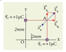
The acceleration experienced by an electron placed at point A is
\(\vec { a_{ A } } =\frac { \vec { F } }{ m } =\frac { q\vec { { E }_{ A } } }{ m } \)
=\(\frac { (-1.6\times 10^{ -19 })\times (2.25\times 10^{ 9 })(\hat { i } +\hat { j } ) }{ 9.1\times { 10 }^{ -31 } } \)
= -3.95 x 10²⁰ \((\hat { i } +\hat { j } )\)Nkg-1
The electron is accelerated in a direction exactly opposite to \(\vec { { E }_{ A } } \).
18.
The relation between drift velocity of electrons and current in a wire of cross- sectional area A is
\({ v }_{ d }=\frac { I }{ neA } =\frac { 0.2 }{ 8.4\times { 10 }^{ 28 }\times 1.6\times { 10 }^{ -19 }\times 0.5\times { 10 }^{ -6 } }\)
vd = 0.03 x 10⁻³ m s-1
19.
(i) The effect of diffraction has an adverse effect in the sharpness of the image tormed.
(ii) There is always a spread of central maximum in the image for every point of the object, for every point of the object acts as a point source.
(iii) The condition for central maximum (or first minimum) produced by rectangular slit is given by the equation,
\(a \sin \theta=\lambda\) ....(1)
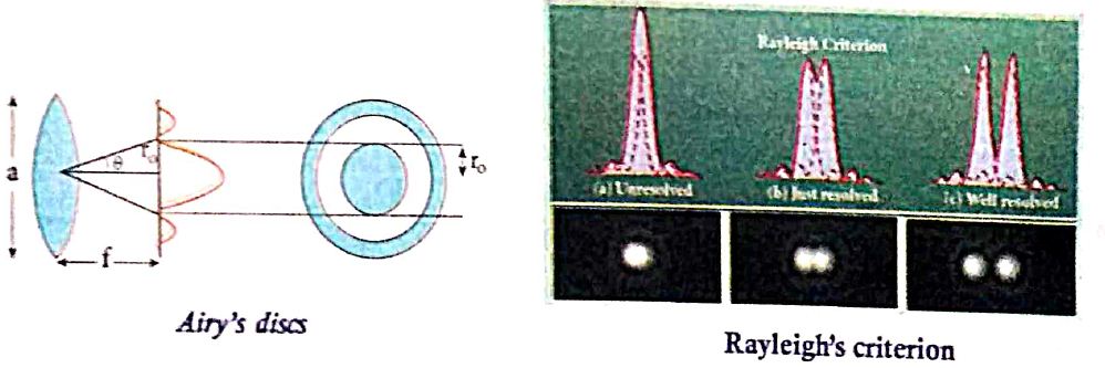
(iv) But, a circular slit (aperture) produces diffraction pattern of concentric circles as shown in Figure.
(v) These are known as Airy's discs. Most of the optical instruments form images of objects only through the circular slits.
(vi) The condition for central maximum (or) first minimum for circular slit is,
\(\text { a } \sin \theta=1.22 \lambda\) .....(2)
(vii) Here, the numerical value 1.22 appears in the expression for central maximum (or) first minimum formed by circular slits.
For small angles,\(sin\theta = \theta\), the above equation becomes,
\(a\theta = 1.22\lambda\)
Rewriting further,
\(\theta=\frac{1.22 \lambda}{a}\) ......(3)
Form thegeometry, \(\theta=\frac{r_0}{f}\)
Substituting for in equation (3) and rearranging gives
\(r_0=\frac{1.22 \lambda f}{a}\) ....(4)
(viii) For example, let two point-sources of light close to cach other form image on a screen. The diffraction pattern of one point-source may overlap with another and produce a blurred image (or) un-resolved image as shown in Figure (a). To obtain a quality image (or) well resolved image, the two point-sources must be kept apart in such a way that their diffraction patterns do not overlap as shown in Figure (c).
(ix) According to Rayleigh's criterion, the two points on an image are said to be just resolved when the central maximum of one diffraction pattern coincides with the first minimum of the other and vice-versa as shown in Figure (b).
20.
(i) Let us consider a thin lens made up of a medium of refractive index n2 is placed in a medium of refractive index n1. Let R1 and R2 be the radii of curvature of two spherical surfaces (1) and (2) respectively and P be the pole.
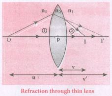
(ii) Consider a point object 'O' on the principal axis. A paraxial ray from 'O' which falls very close to P, after refraction at the surface (1) forms image at 1'.
(iii) Before it does so, it is again refracted by the surface (2). Therefore the final image is formed at I.
(iv) The general equation for the refraction at a single spherical surface is given from Equation,
\(\cfrac { { n }_{ 2 } }{ v } -\cfrac { { n }_{ 1 } }{ v} =\cfrac { \left( { n }_{ 2 }-{ n }_{ 1 } \right) }{ { R } } \)
For the refracting surface (1), the light goes from n1 to n2
\(\cfrac { { n }_{ 2 } }{ v' } -\cfrac { { n }_{ 1 } }{ u } =\cfrac { \left( { n }_{ 2 }-{ n }_{ 1 } \right) }{ { R }_{ 1 } } \) .....(1)
For the refracting surface (2), the light goes from n2 to n1
\(\frac{n_{1}}{v}+\frac{n_{2}}{v^{\prime}}=\frac{\left(n_{1}-n_{2}\right)}{R_{2}}\) ......(2)
For surface (2) I' acts as virtual object.
Adding the above two equations (1) and (2)
\(\cfrac { { n }_{ 1 } }{ v } -\cfrac { { n }_{ 1 } }{ u } =\left( { n }_{ 2 }-{ n }_{ 1 } \right) \left( \cfrac { 1 }{ { R }_{ 1 } } -\cfrac { 1 }{ { R }_{ 2 } } \right) \)
on further simplifying and rearranging,
\(\cfrac { 1 }{ v } -\cfrac { 1 }{ u } =\left( \cfrac { { n }_{ 2 }-{ n }_{ 1 } }{ { n }_{ 1 } } \right) \left( \cfrac { 1 }{ { R }_{ 1 } } -\cfrac { 1 }{ { R }_{ 2 } } \right) \)
\(\cfrac { 1 }{ v } -\cfrac { 1 }{ u } =\left( \cfrac { { n }_{ 2 } }{ n_{ 1 } } -1 \right) \left( \cfrac { 1 }{ { R }_{ 1 } } -\cfrac { 1 }{ { R }_{ 2 } } \right) \) ....(3)
If the object is at infinity, the image is formed at the focus of the lens. Thus, for u = \(\infty\), v = f. Then the equation becomes.
\(\cfrac { 1 }{ f } -\cfrac { 1 }{ \infty } =\left( \cfrac { { n }_{ 2 } }{ { { n }_{ 1 } } } -1 \right) \left( \cfrac { 1 }{ { R }_{ 1 } } -\cfrac { 1 }{ { R }_{ 2 } } \right) \)
\(\cfrac { 1 }{ f } =\left( \cfrac { { n }_{ 2 } }{ { n }_{ 1 } } -1 \right) \left( \cfrac { 1 }{ { R }_{ 1 } } -\cfrac { 1 }{ { R }_{ 2 } } \right) \) ......(4)
If the lens is kept in air, then we can take n2 = n and n1 = 1. So the equation (4) becomes,
\(\\ \cfrac { 1 }{ f } =\left( n-1 \right) \left( \cfrac { 1 }{ { R }_{ 1 } } -\cfrac { 1 }{ { R }_{ 2 } } \right) \) ..(5)
The above equation is called the lens maker's formula.
Significance:
It tells the lens manufacturers what curvature is needed to make a lens of desired focal length with a material of particular refractive index to make a lens of desired focal length. This formula holds good also for a concave lens.
21.
When electron jumps from higher energy stationary orbit (m) to lower energy stationary orbit (n), emit radiation.
Wave number (or) Wave length of the emitted radiation is given by,
\(\frac{1}{\lambda}=R\left[\frac{1}{n^{2}}-\frac{1}{m^{2}}\right]=\bar{v}\)
V - Ware number; R- Rydberg constant = 1.09737 x 10⁷ m-1
m > n (where m, n are integers)
(a) Lyman series:
When electron jumps from any outer orbit to first orbit, (n = 1 and m = 2,3,4.......) the wave number or wavelength of spectral lines lies in ultra-violet region is
\(\bar{v}=\frac{1}{\lambda}=\mathrm{R}\left[\frac{1}{1^{2}}-\frac{1}{\mathrm{~m}^{2}}\right]\)
(b) Balmer series:
Wher electron jumps from any outer orbit to second orbit, (n = 2 and m = 3, 4, 5.......) the wave number or wavelength of spectral lines lies in visible region is,
\(\bar{v}=\frac{1}{\lambda}=R\left[\frac{1}{2^{2}}-\frac{1}{m^{2}}\right]\)
(c) Paschen series:
When electron jumps from any outer orbit to third orbit, (n = 3 and m = 4, 5, 6.......) the wave number or wavelength of spectral lines lies in infra red (Near IR) region is
\(\bar{v}=\frac{1}{\lambda}=R\left[\frac{1}{3^{2}}-\frac{1}{m^{2}}\right]\)
(d) Bracket series:
When electron jumps from any outer orbit to fourth orbit, (n = 4 and m = 5, 6, 7.......) the wave number or wavelength of spectral lines lies in infra red (Middle IR) region is
\(\bar{v}=\frac{1}{\lambda}=R\left[\frac{1}{4^{2}}-\frac{1}{m^{2}}\right]\)
(e) Pfund series:
When electron jumps from any outer orbit to fifth orbit, (n - 5 and m = 6, 7, 8.......) the wave number or wavelength of spectral lines lies in infra red (far IR) region is
\(\bar{v}=\frac{1}{\lambda}=R\left[\frac{1}{5^{2}}-\frac{1}{m^{2}}\right]\)
22.
(i) Consider a circuit containing a resistor of resistance R, a inductor of inductance L and a capacitor of capacitance C connected across an alternating voltage source (Figure ). The instantaneous value of the alternating voltage is given by the equation
ሀ = Vm sin ωt ......(1)
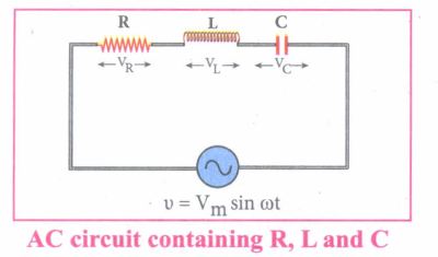
(ii) Let i be the resulting circuit current in the circuit at that instant. As a result, the voltage is developed across R, Land C.
(iii) We know that voltage across R (VR) is in phase with i, voltage across L (VL) leads i by \(\frac { \pi }{ 2 } \) and voltage across C (Vc) lags behind i by \(\frac { \pi }{ 2 } \)
(iv) The phasor diagram is drawn with current as the reference phasor. The current is represented by the phasor \(\vec { OI } \), VR by \(\vec { OA } \); VL by \(\vec { OB } \); Vc by \(\vec { OC } \) as shown in Figure.
(v) The length of these phasors are OI = Im, OA = ImR, OB = ImXL; OC = ImXC
The circuit is either effectively inductive or capacitive or resistive that depends on the value of VL or VC. Let us assume that VL>VC so that nef voltage drop across L-C combination is VL - VC which is represented by a phasor \(\vec { OD } \)
(vi) By parallelogram law, the diagonal \(\vec { OE } \) gives the resultant voltage ሀ of VR and (VL - VC) and its length OE is equal to Vm Therefore,
V2m = V2R + (VL - VC)2 = \(\sqrt { { ({ { I }_{ m }R) } }^{ 2 }+{ ({ I }_{ m }{ X }_{ L }-{ I }_{ m }{ X }_{ C }) }^{ 2 } }=I_m \sqrt {R^2+({X_L-X_C)}^2}\)
or \({ I }_{ m }=\frac { { V }_{ m } }{ \sqrt { R^{ 2 }+({ { X }_{ L }-{ X }_{ C }) }^{ 2 } } } \) ......(2)
\((or) { I }_{ m }=\frac { { V }_{ m } }{ Z } \) where z = \(\sqrt { { R }^{ 2 }+({ { X }_{ L }-{ X }_{ C }) }^{ 2 } } \) ......(3)
(vii) Z is called impedance of the circuit which refers to the effective opposition to the circuit current by the series RLC circuit. The voltage triangle and impedance triangle are given in the Figure.
.JPG)
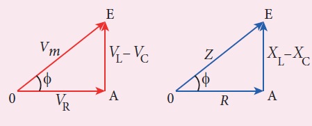
(viii) From phasor diagram, the phase angle between v and i is found out from the following relation
\(tan\phi =\frac { V_{ L }-{ V }_{ C } }{ { V }_{ R } } =\frac { X_{ L }-{ V }_{ C } }{ R } \)
Special cases:
(i) If XL > XC (XL - XC) is positive and phase angle \(\phi \) is also positive. It means that the applied voltage leads the current by \(\phi \) (or current lags behind voltage by \(\phi\)). The circuit is inductive.
∴v = Vm sin ωt; i = Im sin(ωt - \(\phi \))
(ii) If XL < XC (XL - XC) is negative and\(\phi \) is also negative. Therefore current leads voltage by \(\phi \) (or voltage lags behind current by\(\phi \)) and the circuit is capacitive.
∴ = Vm sin ωt; i = Im sin(ωt + \(\phi \))
(ii) If XL = XC \(\phi \) is zero. Therefore current and voltage are in the same phase and the circuit is resistive
∴v = Vm sin ωt, i = Im sinωt
23.
Distribution of charges in a conductor:
(i) Consider two conducting spheres A and B of radii r1 and r2 respectively connected to each other by a thin conducting wire as shown in the Figure. The distance between the spheres is much greater than the radii of either spheres.
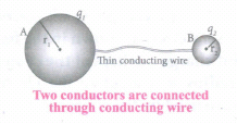
(ii) If a charge Q is introduced into any one of the spheres, this charge Q is redistributed into both the spheres such that the electrostatic potential is same in both the spheres. They are now uniformly charged and attain electrostatic equilibrium. Let q1 be the charge residing on the surface of sphere A and q2 is the charge residing on the surface of sphere B such that Q = q1 + q2, The charges are distributed only on the surface and there is no net charge inside the conductor.
The electrostatic potential at the surface of the sphere A is given by
\({ V }_{ A }=\frac { 1 }{ 4\pi { \varepsilon }_{ 0 } } \frac { { q }_{ 1 } }{ { r }_{ 1} } \quad \quad ...(1)\)
(iii) The electrostatic potential at the surface of the sphere B is given by ,
\({ V }_{ B }=\frac { 1 }{ 4\pi { \varepsilon }_{ 0 } } \frac { { q }_{ 2 } }{ { r }_{ 2 } } \) ...(2)
iv) The surface of the conductor is an equipotential. Since the spheres are connected by the conducting wire, the surfaces of both the spheres together form an equipotential surface.
This implies that
VA= VB
or \(\frac { { q }_{ 1 } }{ { r }_{ 1 } } =\frac { { q }_{ 2 } }{ { r }_{ 2 } } \) ...(3)
v) Let us take the charge density on the surface of sphere A and charge density on the surface of sphere B is σ2.This implies that q1 = 4πr12σ1 and 4πr22σ2 substituting these values into equation (3), we get
σ1r1 = σ2r2 ...(4)
from which we conclude that σr = constant ...(5)
Lightning conductor:
It is used to protect tall buildings from lightning strikes.
Principle:
(i) Action at points (or) corona discharge.
(ii) This device consists of a long thick copper rod passing from top of the building to the ground.
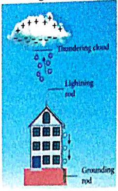
(iii) The upper end of the rod has a sharp spike or a sharp needle as shown in Figure.
(iv) The lower end of the rod is connected to copper plate which is buried deep into the ground.
(v) When a negatively charged cloud is passing above the building, it causes a positive charge on the spike. Since the induced charge density on thin sharp spike is large, it results in a corona discharge. This positive Charge ionizes the surrounding air which in turn neutralizes the negative charge in the cloud.
(vi) The negative charge pushed to the spikes passes through the copper rod and is safely diverted to the Earth. The lightning arrester does not stop the lightning; rather it diverts the lightning to the ground safely.
24.
(i) The meter bridge is another form of Wheatstone's bridge. It consists of a uniform manganin wire AB of one meter length.
(ii) This wire is stretched along a meter scale on a wooden board between two copper strips C and D. Between these two copper strips another copper strip E is mounted to enclose two gaps G1 and G2.
(iii) An unknown resistance P is connected in G1 and a standard resistance Q is connected in G2. A jockey (conducting wire) is connected to the terminal E on the central copper strip through a galvanometer (G) and a high resistance (HR).
(iv) The exact position of jockey on the wire can be read on the scale. A Lechlanche cell and a key (K) are connected across the ends of the bridge wire.

(v) The position of the jockey on the wire is adjusted so that the galvanometer shows zero deflection. Let the position of jockey at the wire be at J.
(vi) The resistances corresponding to AJ and JB of the bridge wire now form the resistance R and S of the Wheatstone's bridge. Then for the bridge balance.
\(\cfrac { P }{ Q } =\cfrac { R }{ S } =\cfrac { { r }.AJ }{ { r }.JB } \)
where r' is the resistance per unit length of wire
\(\cfrac { P }{ Q } =\cfrac { AJ }{ JB } =\cfrac { { l }_{ 1 } }{ { l }_{ 2 } } \)
\(P=Q\cfrac { { l }_{ 1 } }{ { l }_{ 2 } } \)
(vii) By interchanging P and Q, another set of readings are taken and the average value of P is value of unknown resistance.
25.
(i) The ohm's law can be derived from the equation \(J=\sigma E\) Consider a segment of wire of length I and cross-sectional area A as shown in Figure.
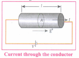
(ii) When a potential difference V is applied across the wire, a net electric field is created in the wire which constitutes the current in the wire.
(iii) For simplicity, we assumed that the electric field is uniform in the entire length of the wire, the potential difference (voltage V) can be written as V = EI
(iv) As we know, the magnitude of current density
\(J=\sigma E=\sigma \cfrac { V }{ l } \)
(v) But \(J=\cfrac { I }{ A } \), so we write the equation as,
\(\cfrac { I }{ A } =\sigma \cfrac { V }{ l } \)
(vi) By rearranging the above equation we get,
\(V=I\left( \cfrac { I }{ \sigma A } \right) \)
(vii) The quantity \(\cfrac { l }{ \sigma A } \)is called resistance of the conductor and it is denoted as R. Note that the resistance is directly proportional to the length of the conductor and inversely proportional to area of cross-section.
(viii) Therefore, the macroscopic form of ohm's law can be stated as V = IR.

12th Standard Syllabus & Materials
12th Standard
TN 12th Computer Applications வலையமைப்பு வடமிடல் Sample Question Papers Study Material - QB365 Set A
NEW12th Standard
TN 12th Computer Applications களப்பெயர் முறைமை (DNS) Sample Question Papers Study Material - QB365 Set A
NEW12th Standard
TN 12th Computer Applications வலையமைப்பு எடுத்துக்காட்டுகள் மற்றும் நெறிமுறைகள் Sample Question Papers Study Material - QB365 Set A
NEW12th Standard
TN 12th Computer Applications கணினி வலையமைப்பு ஓர் அறிமுகம் Sample Question Papers Study Material - QB365 Set A



Tamilnadu Stateboard 12th Standard Subjects

Maths

Chemistry
Physics

Biology

Computer Science

Business Maths and Statistics

Economics

Commerce

Accountancy

History

Computer Applications
Biology
Computer Technology
Computer Applications
Computer Science
Business Maths and Statistics
Commerce
Economics
Maths
Chemistry
Physics
Computer Technology
History
Accountancy

Tamil

English

French
Tamilnadu Stateboard Standards

