
 100% FREE ACCESS
12th Standard Syllabus & Materials
12th Standard
TN 12th Computer Applications மின்னணு தரவு பரிமாற்றம் Sample Question Papers Study Material - QB365 Set A
NEW12th Standard
TN 12th Computer Applications மின் - வணிக பாதுகாப்பு அமைப்புகள் Sample Question Papers Study Material - QB365 Set A
NEW12th Standard
TN 12th Computer Applications மின்னணு செலுத்தல் முறைகள் Sample Question Papers Study Material - QB365 Set A
NEW12th Standard
TN 12th Computer Applications மின் - வணிகம் Sample Question Papers Study Material - QB365 Set A
NEW12th Standard
TN 12th Computer Applications திறந்த மூல கருத்துருக்கள் Sample Question Papers Study Material - QB365 Set A
NEW12th Standard
TN 12th Computer Applications வலையமைப்பு வடமிடல் Sample Question Papers Study Material - QB365 Set A

Published on: 01/06/2021
QB365 provides detailed and simple solution for every Book back Questions in class 12 Physics Subject. It will helps to get more idea about question pattern in every book back questions with solution.
Download Tamil Nadu 12th Standard Physics question papers, model tests, one-mark questions, important questions, and public exam papers in PDF format. Free study materials and answer keys for TN State Board students.
Questions + Answers key
Take MCQ Physics Test1.
A closed coil of 40 turns and of area 200 cm2, is rotated in a magnetic field of flux density 2 Wb m–2. It rotates from a position where its plane makes an angle of 30o with the field to a position perpendicular to the field in a time 0.2 s. Find the magnitude of the emf induced in the coil due to its rotation.
2.
Using the relation \(\overset { \rightarrow }{ B } =\mu _{ ° }(\overset { \rightarrow }{ H+ } \overset { \rightarrow }{ M } )\) show that \({ x }_{ m }={ \mu }_{ r }-{ 1 }\)
3.
Calculate the magnetic flux coming out from closed surface containing magnetic dipole (say, a bar magnet) as shown in figure.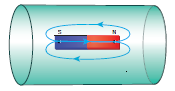
4.
Calculate the number of electrons in one coulomb of negative charge.
5.
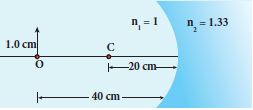
Find the size of the image formed in the given figure
6.
Consider a parallel plate capacitor which is connected to an 230 V RMS value and 50 Hz frequency. If the separation distance between the plates of the capacitor and area of the plates are 1 mm and 20 cm2 respectively. Calculate the displacement current at t = 1 s.
7.
Obtain the expression for energy stored in the parallel plate capacitor.
8.
Derive an expression for the torque experienced by a dipole due to a uniform electric field.
9.
State and explain Kirchhoff ’s rules
10.
The resistance of a wire is 20 Ω. What will be new resistance, if it is stretched uniformly 8 times its original length?
11.
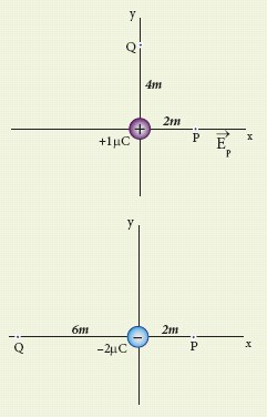
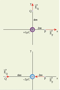
Calculate the electric field at points P, Q for the following two cases, as shown in the figure.
(a) A positive point charge +1 μC is placed at the origin.
(b) A negative point charge -2 μC is placed at the origin.
12.
What do you mean by electron emission? Explain briefly various methods of electron emission.
13.
Discuss the conversion of galvanometer into an ammeter and also a voltmeter.
14.
Obtain a relation for the magnetic field at a point along the axis of a circular coil carrying current using Biot-Savart law.
15.
Give an illustration of determining direction of induced current by using Lenz’s law.
1.
N = 40 turns; B = 2 Wb m-2
A = 200 cm2 = 200 x 10-4 m2;
Initial flux, \(\Phi_i\) = BA cos\(\theta\)
= 2 x 200 x 10-4 x cos60o
since θ = 90°− 30°= 60°
\(\Phi_i\)= 2 x 10⁻² Wb
Final flux, \(\Phi_f\) = BA cos\(\theta\)
= 2 x 200 x 10-4 x cos0o since \(\theta\) = 0o
\(\Phi_f\) = 4 x 10⁻²Wb
Magnitude of the induced emf is
\(ε =N\frac { d{ \Phi }_{ B } }{ dt } \)
\(=\frac { 40\times (4\times { 10 }^{ -2 }-2\times { 10 }^{ -2 }) }{ 0.2 } =4V\)
2.
\(\overset { \rightarrow }{ B } =\mu _{ ° }(\overset { \rightarrow }{ H+ } \overset { \rightarrow }{ M } )\)
But from equation (3.33), in vector form,
\(\overset { \rightarrow }{ M } ={ x }_{ m }\overset { \rightarrow }{ H } \)
Hence, \(\overset { \rightarrow }{ B } =\mu _{ ° }({ x }_{ m }+1)\overset { \rightarrow }{ H } \Rightarrow \overset { \rightarrow }{ B } =\mu \overset { \rightarrow }{ H } \)
where, \(\mu =\mu _{ ° }({ x }_{ m }+1)\Rightarrow { x }_{ m }+1=\frac { \mu }{ \mu _{ ° } } =\mu _{ r }\)
\(\Rightarrow { x }_{ m }=\mu _{ r }-1\)
3.
The total flux emanating from the closed surface S enclosing the dipole is zero. So,
\({ \Phi }_{ B }=\oint { \overset { \rightarrow }{ B } .d\overset { \rightarrow }{ A } } =0\)
Here the integral is taken over closed surface. Since no isolated magnetic pole (called magnetic monopole) exists, this integral is always zero,
\(\oint { \overset { \rightarrow }{ B } .d\overset { \rightarrow }{ A } } =0\)
This is similar to Gauss’s law in electrostatics.
4.
According to the quantisation of charge
q = ne
Here q = 1C. So the number of electrons in 1 coulomb of charge is
n = \(\frac { q }{ e } =\frac { 1C }{ 1.6\times 10^{ -19 } } \) = 6.25 x 10¹⁸ electrons
5.
Given, u = –40 cm, R = –20 cm, n1 = 1 and n2 = 1.33
Equation for single spherical surface is
\(\cfrac { { n }_{ 2 } }{ v } -\cfrac { { n }_{ 1 } }{ u } =\cfrac { \left( { n }_{ 2 }-{ n }_{ 1 } \right) }{ R } \)
Substituting the values
\(\cfrac { 1.33 }{ v } -\cfrac { 1 }{ -40 } =\cfrac { \left( 1.33-1 \right) }{ -20 } ;\cfrac { 1.33 }{ v } +\cfrac { 1 }{ 40 } =\cfrac { \left( 0.33 \right) }{ -20 } \)
\(\cfrac { 1.33 }{ v } =\cfrac { \left( 0.33 \right) }{ 20 } -\cfrac { 1 }{ 40 } ;\)
\(\cfrac { 1.33 }{ v } =\cfrac { 0.66-1 }{ 40 } =\cfrac { 1.66 }{ 40 } \)
\(v=-40\times \cfrac { 1.33 }{ 1.66 } =-32.0cm\)
The equation for magnification is,\(m=\cfrac { { h }_{ 2 } }{ { h }_{ 1 } } =\cfrac { { { n }_{ 1 }v } }{ { n }_{ 2 }u } \)
\(\cfrac { { h }_{ 2 } }{ 1.0 } =\cfrac { \left( 1.0 \right) \times \left( -32 \right) }{ \left( 1.33 \right) \times \left( -40 \right) } =0.6cm\) (or) h2 = 0.6cm
The erect virtual image of height 0.6 cm is formed at 32.0 cm to the left of the single spherical surface.
6.
Potential difference between the plates of the capacitor,
\(V=V_{\max } \sin 2 \pi f t\)
\(=230 \sqrt{2} \sin (2 \pi \times 50 t)\)
\(\therefore V=325 \sin 100 \pi t\)
d = 1 mm = 1 x 10⁻³ m
A = 20 cm2 = 20 x 10–4 m2
Displacement current, \(i_{d}=\epsilon_{0} \frac{d \Phi_{E}}{d t}=\epsilon_{\circ} \frac{d(\mathrm{EA})}{d t}\)
\(\therefore i_{d}=\frac{\epsilon_{0} A}{d}\left[\frac{d V}{d t}\right] \quad\left[\because E=\frac{V}{d}\right]\)
\(=\frac{\epsilon_{0} A}{d}(325)(100 \pi) \cos 100 \pi t\)
\(=\left(\begin{array}{l} 8.85 \times 10^{-12} \times 20 \times 10^{-4} \times 325 \\ \times 100 \times 3.14 \times \cos (100 \pi \times 1) \end{array}\right) /\left(1 \times 10^{-3}\right)\)
\(\begin{aligned}=1.81 \times 10^{-6} \mathrm{~A}=1.81 \mu \mathrm{A}[\because \cos (100 \pi \times 1)=1] \end{aligned}\)
7.
Energy stored in the capacitor
i) Capacitor not only stores the charge but also it stores energy. When a battery is connected to the capacitor, electrons of total charge - Q are transferred from one plate to the other plate. To transfer the charge, work is done by the battery. This work done is stored as electrostatic potential energy in the capacitor.
ii) To transfer an infinitesimal charge dQ for a potential difference V, the work done is given by
dW = V dQ
Where \(V=\frac { Q }{ C } \) .....(1)
iii) The total work done to charge a capacitor is
\(W=\int _{ 0 }^{ Q }{ \frac { Q }{ C } } dQ=\frac { { Q }^{ 2 } }{ 2C } \quad \quad ....(2)\)
This work done is stored as electrostatic potential energy (UE) in the capacitor.
\({ U }_{ E }=\frac { { Q }^{ 2 } }{ 2C } =\frac { 1 }{ 2 } { CV }^{ 2 },\quad (\therefore Q=CV)\quad ....(3)\)
(iv) This stored energy is thus directly proportional to the capacitance of the capacitor and the square of the voltage between the plates of the capacitor.Substituting \(C=\frac { { \varepsilon }_{ 0 }A }{ d } \) and V = Ed.
\(U=\frac { 1 }{ 2 } \left( \frac { { \varepsilon }_{ 0 }A }{ d } \right) { (Ed) }^{ 2 }=\frac { 1 }{ 2 } { \varepsilon }_{ 0 }(Ad){ E }^{ 2 }\quad \quad \quad \quad \quad ...(4)\)
where Ad = volume of the space between the capacitor plates. The energy stored per unit volume of space is defined as energy density \({ u }_{ E }=\frac { U }{ Volume } \)
Equation (4) ⇒ \({ u }_{ E }=\frac{1}{2}{ \varepsilon }_{ 0 }{ E }^{ 2 }\).....(5)
(v) From equation (5),
(a) We infer that the energy is stored in the electric field existing between the plates of the capacitor. Once the capacitor is allowed to discharge, the energy is retrieved.
(b) The energy density depends only on the electric field and not on the size of the plates of the capacitor.
(c) This is true for the electric field due to any type of charge configuration.
8.
Torque experienced by an electric dipole in the uniform electric field:
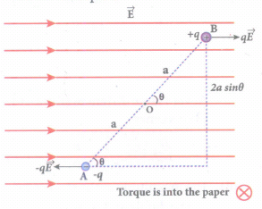
Consider an electric dipole of dipole moment \(\vec { p } \) placed in a uniform electric field \(\vec { E } \) whose field lines are equally spaced and point in the same direction. The charge +q will experience a force \(q\vec { E } \) in the direction of the field and charge -q will experience a force \(-q\vec { E } \) in a direction opposite to the field. Since the external field \(\vec { E } \) is uniform, the total force acting on the dipole is zero. These two forces acting at different points will constitute a couple and the dipole experience a torque. This torque tends to rotate the dipole.
The total torque on the dipole about the point O
\(\vec{\tau}=\overrightarrow{O A} \times(-q \vec{E})+\overrightarrow{O B} \times q \vec{E}\) ......(1)
Using right-hand corkscrew rule, it is found that total torque is perpendicular to the plane of the paper and is directed into it.
The magnitude of the total torque
\(\tau =|\vec { OA } |\left( -q\vec { E } \right) |sin\theta +|\vec { OB } ||\vec { E } |sin\theta \)
\(\tau =qE.2a\quad sin\theta \) ....(2)
where θ is the angle made by \(\vec { p } \) with \(\vec { E } \) since p = 2aq, the torque is written in terms of the vector product as
\(\vec { \tau } =\vec { p } \times \vec { E } \) ...(3)
The magnitude of this torque is \(\tau \) = pEsin \(\theta \) and is maximum when θ = 90o.
This torque tends to rotate the dipole and align it with the electric field \(\vec{E}\). Once \(\vec{p}\) is aligned with \(\vec{E}\), the total torque on the dipole becomes zero.
9.
Kirchhoff's First rule: (current rule)
(i) It states that the algebraic sum of the currents at any junction of a circuit is zero. It is a statement of law of conservation of electric charge.
(ii) All charges that enter a given junction in a circuit must leave that junction since charge cannot build up or disappear at a junction. By convention current entering the junction is taken as positive and current leaving the junction is taken as negative.
Applying law to the junction A in Figure.
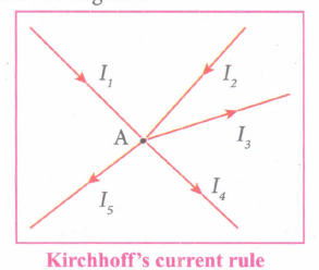
\({ I }_{ 1 }+{ I }_{ 2 }-{ I }_{ 3 }-{ I }_{ 4 }-{ I }_{ 5 }=0\)
(or)
\({ I }_{ 1 }+{ I }_{ 2 }=I_{ 3 }+{ I }_{ 4 }+{ I }_{ 5 }\)
Kirchhoff's Second rule (Voltage rule or Loop rule)
(i) It states that in a closed circuit the algebraic sum of the products of the current and resistance of each part of the circuit is equal to the total emf included in the circuit.
(ii) This rule follows from the law of conservation of energy for an isolated system (The energy supplied by the emf sources is equal to the sum of the energy delivered to all resistors).
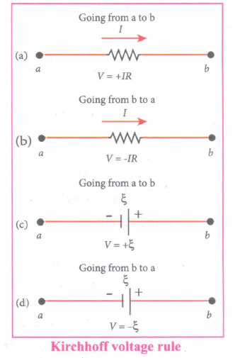
(iii) Kirchhof's voltage rule has to be applied only when all currents in the circuit reach a steady state condition.
(iv) The current in the various branches are constant. The product of current and resistance is taken as positive when the direction of the current is followed.
(v) Suppose if the direction of current is opposite to the direction of the loop, then product of current and voltage across the resistor is negative. It is shown in Figure (a) and (b).
(vi) The emf is considered positive when proceeding from the negative to the positive terminal of the cell.
10.
R1 = 20 Ω, R2 = ?
Let the original length of the wire (l1) be l.
New length, l2 = 8l1 (i.,e) l2 = 8l
Original resistance, R1 = \(\rho \frac { { l }_{ 1 } }{ { A }_{ 1 } } \)
New resistance R2 = \(\rho \frac { { l }_{ 2 } }{ { A }_{ 2 } } =\frac { \rho (8l) }{ { A }_{ 2 } } \)
Though the wire is stretched, its volume is unchanged.
Initial volume = Final volume
A1l1 = A2l2 , A1l = A2(8l)
\(\frac { { A }_{ 1 } }{ { A }_{ 2 } } =\frac { 8l }{ l } =8\)
By dividing equation R2 by equation R1, we get
\(\frac { { R }_{ 2 } }{ { R }_{ 1 } } =\frac { \rho (8l) }{ { A }_{ 2 } } \times \frac { { A }_{ 1 } }{ \rho l } \)
\(\frac { { R }_{ 2 } }{ { R }_{ 1 } } =\frac { { A }_{ 1 } }{ { A }_{ 2 } } \times 8\)
Substituting the value of \(\frac { { A }_{ 1 } }{ { A }_{ 2 } } \), we get
\(\frac { { R }_{ 2 } }{ { R }_{ 1 } } =8\times 8=64\)
R2 = 64 x 20 = 1280 Ω
Hence, stretching the length of the wire has increased its resistance.
11.
Case (a)
The magnitude of the electric field at point P is
Ep = \(\frac { 1 }{ 4\pi \varepsilon _{ 0 } } \frac { q }{ { r }^{ 2 } } =\frac { 9\times { 10 }^{ 9 }\times 1\times 10^{ -6 } }{ 4 } \)
= 2.25 x 10³ NC-1
Since the source charge is positive, the electric field points away from the charge. So the electric field at the point P is given by
\(\bar { { E }_{ p } } \) = 2.25 x 10³ NC-1
For the point Q
\(|\vec { { E }_{ Q } } |=\frac { 9\times 10^{ 9 }\times 1\times { 10 }^{ -6 } }{ 16 } \) = 0.56 x 10³ NC-1
Hence \(\vec { { E }_{ Q } } \) = 0.56 x 10³\(\hat { j } \) NC-1
Case (b)
The magnitude of the electric field at point P
\(\bar { { E }_{ p } } =\frac { kq }{ r^{ 2 } } =\frac { 1 }{ 4\pi { \varepsilon }_{ 0 } } \frac { q }{ { r }^{ 2 } } =\frac { 9\times 10^{ 9 }\times 2\times 10^{ -6 } }{ 4 } \)
= 4.5 x 10³ NC-1
Since the source charge is negative, the electric field points towards the charge. So the electric field at the point P is given by
\(\vec { E_{ p } } \) = -4.5 x 10³\(\hat { i } \)NC-1
For the point Q, \(|\vec { { E }_{ Q } } |\frac { 9\times 10^{ 9 }\times 2\times { 10 }^{ -6 } }{ 36 } \)
= 0.5 x 10³ NC-1
\(\vec { E_{ Q } } \) = 0.5 x 10³\(\hat { i } \)NC-1
At the point Q the electric field is directed along the positive x-axis.
12.
(i) In metals, the electrons in the outer most shells are loosely bound to the nucleus. Even at room temperature, there are a large number of free electrons which are moving inside the metal in a random manner. Through they move freely inside the metal they cannot leave the surface of the metal. The reason is that when free electrons reach the surface of the metal they are attracted by the positive nuclei of the metal. It is attractive pull which will not allow free electrons to leave the metallic surface at room temperature.
(ii) In order to leave the metallic surface, the free electrons must cross a potential barrier created by the positive nuclei of the metal. The potential barrier. which prevents free electrons from leading the metallic surface is called surface barrier.
(iii) Whenever an additional energy is given to the free electrons, they will have sufficient energy to cross the surface barrier. And they escape from the metallic surface. The liberation of electrons from any surface of a substance is called electron emission.
(iv) The minimum energy needed for an electron to escape from the metal surface is called work function of that metal.
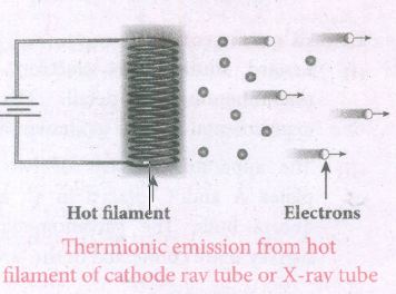
(a) Thermionic emission
(i) When a metal is heated to a high temperature, the free electrons on the surface of the metal get sufficient energy in the form of thermal energy so that they are emitted from the metallic surface. This type of emission is known a thermonic emission.
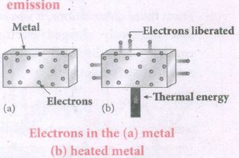
(ii) The intensity of the thermionic emission (the number of electrons emitted) depends on the metal used and its temperature.
(iii) Examples: cathode ray tubes, electron microscopes, X-ray tubes etc.
(b) Field emission
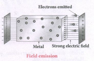
(i) Electric field emission occurs when a very strong electric field is applied across the metal.
(ii) This strong field pulls the free electrons and helps them to overcome the surface barrier of the metal.
(iii) Ex: Field ermssion scanning electron microscopes, Field-emission display etc.
(c) Photo electric emission
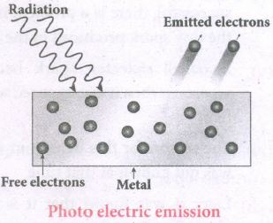
(i) When an electromagnetic radiation of suitable frequency is incident on the surface of the metal, the energy is transferred from the radiation to the free electrons.
(ii) Hence, the free electrons get sufficient energy to cross the surface barrier and the photo electric emission takes place.
(iii) The number of electrons emitted depend on the intensity of the incident radiation.
(iv) Examples: Photo diodes, photo electric cells etc.
(d) Secondary emission
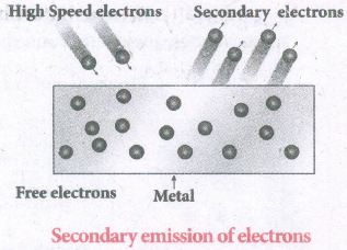
(i) When a beam of fast-moving electrons strikes the surface of the metal, the kinetic energy of the striking electrons is transferred to the free electrons on the metal surface.
(ii) Thus the free electrons get sufficient kinetic energy so that the secondary emission of electron occurs.
(iii) Examples: Image intensifiers, photo multiplier tubes etc.
13.
(i) Galvanometer to an Ammeter:
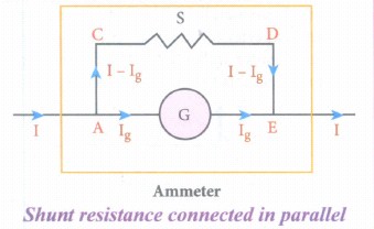
(i) Ammeter is an instrument used to measure current flowing in the electrical circuit.
(ii) The Ammeter must offer low resistance such that it will not change the current passing through it. So, ammeter is connected in series to measure the circuit current.
(iii) A galvanometer is converted into an ammeter by connecting a low resistance in parallel with the galvanometer.
(iv) Let I be the current passing through the circuit. When current I reaches the junction A, it divides into two components.
a) Ig → Current passing through the galvanometer
b) I - Ig → Current passing through the shunt resistance.
(v) The potential difference across the galvanometer is same as the potential difference across the shunt resistance.
\(\mathrm{V}_{\text {galvanometer }} =\mathrm{V}_{\text {shunt }} \)
\(\Rightarrow \mathrm{I}_{\mathrm{g}} \mathrm{R}_{\mathrm{g}} =\left(\mathrm{I}-\mathrm{I}_{g}\right) \mathrm{S} \)
\(\mathrm{S} =\frac{I_{g}}{\left(I-I_{g}\right)} R_{g} \) (or)
\(\mathrm{I}_{\mathrm{g}}=\frac{S}{S+R_{g}} I \Rightarrow I_{g} \propto I\)
Since, the deflection in the galvanometer is proportional to the current passing through it.
\(\theta=\frac{1}{G} I_{g} \Rightarrow \theta \propto I_{g} \Rightarrow \theta \propto I\)
Where, Rg → Galvanometer resistance, S → Shunt resistance.
Since shunt resistance is connected in parallel to galvanometer,
Effective resistance,\(\frac{1}{R_{e f f}}=\frac{1}{R_{g}}+\frac{1}{S} \Rightarrow R_{e f f}=\frac{R_{g} S}{R_{g}+S}=R_{a}\)
Ra ⇒ low resistance. An ideal ammeter has zero resistance.
The percentage error in measuring a current through an ammeter is,
\(\frac{\Delta I}{I} \times 100 \%=\frac{I_{i d e a l}-I_{a c t u a l}}{I_{a c t u a l}} \times 100 \%\)
(ii) Galvanometer to a voltmeter:
i) A voltmeter is an instrument used to measure potential difference across any two points in the electrical circuits.
ii) Voltmeter must have high resistance and when it is connected in parallel, it will rot draw appreciable current so that it will indicate the true potential difference.
iii) A galvanometer is converted into a voltmeter by connecting high resistance Rh in series with galvanometer.
iv) Let Rg be the resistance of galvanometer and Ig be the current with which the galvanometer produces full scale deflection.
v) Since the galvanometer is connected in series with high resistance, the current in the electrical circuit is same as the current passing through the galvanometer.
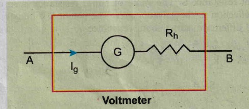
\(\mathrm{I}=\mathrm{I}_{\mathrm{g}} \)
\(\mathrm{I}=I_{g} \Rightarrow I_{g}=\frac{\text { potential difference }}{\text { total resistance }} \)
Since the galvanometer and high resistance are connected in series, the voltmeter resistance is,
\(R_{v} =R_{g}+R_{h} \)
Therefore,
\(I_{g} =\frac{V}{R_{g}+R_{h}} \)
\(\Rightarrow R_{h} =\frac{V}{I_{g}}-R_{g} \)
Note that \(I_{g} \propto V\)
Rh is very large. An ideal voltmeter has infinite resistance
14.
(i) Let 'R' be the radius of a current carrying circular loop.
(ii) I be the current flowing through the wire.
(iii) Let P be a point on the axis of the circular coil at a distance z from its centre 'O'
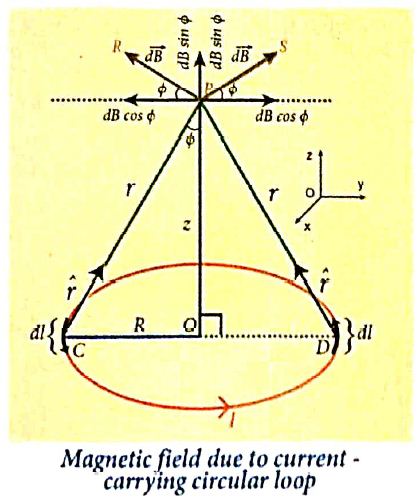
(iv) Take two diametrically opposite element \(\vec { dl } \) at C and D. According to Biot-Savart's law, the magnetic field at P due to the current element at C is
\(d \vec{B}=\frac{\mu_0}{4 \pi} \frac{I d \vec{l} \times \hat{r}}{r^2}\)
The magnitude of \( { d\vec B } \)is
\(d \vec{B}=\frac{\mu_0}{4 \pi} \frac{I d l \sin \theta}{r^2}=\frac{\mu_0}{4 \pi} \frac{I d l}{r^2}\)
where θ is the angle between \(I\vec { dl } \) and \(\vec { r } \). Here, θ = 90o.
\(\vec{B} =\int d \vec{B}=\int d B \sin \phi \hat{k} \)
\(\vec{B} =\frac{\mu_o I}{4 \pi} \int \frac{d l}{r^2} \sin \phi \hat{k} \)
\(\text {But, } \cos \theta =\frac{R}{\left(R^2+z^2\right)^{\frac{1}{2}}} \text { (using Pythagoras theorem) }\)
From ΔOCP
\(\sin \phi=\frac{R}{\left(R^2+z^2\right)^{1 / 2}} \text { and } r^2=R^2+z^2.\)
Substituting these in the above equation, we get,
\(\vec{B}=\frac{\mu_0 I}{4 \pi} \frac{R}{\left(R^2+z^2\right)^{3 / 2}} \hat{k}\left(\int d l\right)\)
If we integrate the line element from 0 to 2πR, we get the net magnetic field \(\vec{B}\) at any point P due to the current - carrying circular loop,
\(\vec{B}=\frac{\mu_0 I}{2} \frac{R^2}{\left(R^2+z^2\right)^{3 / 2}} \hat{k}\)
If the circular coil contains N turns, then the magnetic field is
\(\vec{B}=\frac{\mu_0 N I}{2} \frac{R^2}{\left(R^2+z^2\right)^{3 / 2}} \hat{k}\)
The magnetic field at the centre of the coil is,
\(\vec{B}=\frac{\mu_0NI}{2R}\hat k\) since z= 0
15.
(i) Let us move a bar magnet towards the solenoid, with its north pole pointing the solenoid. This motion increases the magnetic flux of the coil which in turn, induces an electric current.
(ii) Due to the flow of induced current, the coil becomes a magnetic dipole whose two magnetic poles are on either end of the coil.
(iii) In this case, the cause producing the induced current is the movement of the magnet. According to Lenz's law, the induced current should flow in such a way that it opposes the movement of the north pole towards coil
(iv) It is possible if the end nearer to the magnet becomes north pole.
(v) Then it repels the north pole of the bar magnet and opposes the movement of the magnet. Once pole ends are known, the direction of the induced current could be found by using right hand thumb rule.
(vi) When the bar magnet is withdrawn, the nearer end becomes south pole which attracts north pole of the bar magnet, opposing the receding motion of the magnet.
(vii) Thus, the direction of the induced current can be found from Lenz's law.

12th Standard Syllabus & Materials
12th Standard
TN 12th Computer Applications களப்பெயர் முறைமை (DNS) Sample Question Papers Study Material - QB365 Set A
NEW12th Standard
TN 12th Computer Applications வலையமைப்பு எடுத்துக்காட்டுகள் மற்றும் நெறிமுறைகள் Sample Question Papers Study Material - QB365 Set A
NEW12th Standard
TN 12th Computer Applications கணினி வலையமைப்பு ஓர் அறிமுகம் Sample Question Papers Study Material - QB365 Set A
NEW12th Standard
TN 12th Computer Applications PHP-உடன் MySQL-ஐ இணைத்தல் Sample Question Papers Study Material - QB365 Set A



Tamilnadu Stateboard 12th Standard Subjects

Maths

Chemistry
Physics

Biology

Computer Science

Business Maths and Statistics

Economics

Commerce

Accountancy

History

Computer Applications
Biology
Computer Technology
Computer Applications
Computer Science
Business Maths and Statistics
Commerce
Economics
Maths
Chemistry
Physics
Computer Technology
History
Accountancy

Tamil

English

French
Tamilnadu Stateboard Standards



