
 100% FREE ACCESS
12th Standard Syllabus & Materials
12th Standard
TN 12th Computer Applications மின்னணு தரவு பரிமாற்றம் Sample Question Papers Study Material - QB365 Set A
NEW12th Standard
TN 12th Computer Applications மின் - வணிக பாதுகாப்பு அமைப்புகள் Sample Question Papers Study Material - QB365 Set A
NEW12th Standard
TN 12th Computer Applications மின்னணு செலுத்தல் முறைகள் Sample Question Papers Study Material - QB365 Set A
NEW12th Standard
TN 12th Computer Applications மின் - வணிகம் Sample Question Papers Study Material - QB365 Set A
NEW12th Standard
TN 12th Computer Applications திறந்த மூல கருத்துருக்கள் Sample Question Papers Study Material - QB365 Set A
NEW12th Standard
TN 12th Computer Applications வலையமைப்பு வடமிடல் Sample Question Papers Study Material - QB365 Set A

Published on: 01/10/2019
Electromagnetic Induction and Alternating Current
Download Tamil Nadu 12th Standard Physics question papers, model tests, one-mark questions, important questions, and public exam papers in PDF format. Free study materials and answer keys for TN State Board students.
Questions + Answers key
Take MCQ Physics Test1.
A square coil of side 30 cm with 500 turns is kept in a uniform magnetic field of 0.4 T. The plane of the coil is inclined at an angle of 30o to the field. Calculate the magnetic flux through the coil.
2.
Define average value of an alternating current.
3.
List out the advantages of stationary armature-rotating field system of AC generator.
4.
What is meant by mutual induction?
5.
Mention the ways of producing induced emf.
6.
7.
What is meant by electromagnetic induction?
8.
A circular antenna of area 3 m2 is installed at a place in Madurai. The plane of the area of antenna is inclined at 47o with the direction of Earth’s magnetic field. If the magnitude of Earth’s field at that place is 4.1 x 10⁻⁵ T find the magnetic flux linked with the antenna.
9.
The equation for an alternating current is given by i = 77 sin 314t. Find the peak current, frequency, time period and instantaneous value of current at t = 2 ms.
10.
\(\frac{20}{\pi^2}H\) inductor is connected to a capacitor of capacitance C. The value of C in order to impart maximum power at 50 Hz is
50 μF
0.5 μF
500 μF
5 μF
11.
An inductor 20 mH, a capacitor 50 μF and a resistor 40Ω are connected in series across a source of emf V = 10 sin 340 t. The power loss in AC circuit is
0.76 W
0.89 W
0.46 W
0.67 W
12.
In an electrical circuit, R, L, C, and AC voltage source are all connected in series. When L is removed from the circuit, the phase difference between the voltage and current in the circuit is \(\frac{\pi}{3}\). Instead, if C is removed from the circuit, the phase difference is again \(\frac{\pi}{3}\). The power factor of the circuit is
1/2
1/\(\sqrt2\)
1
\(\sqrt3\)/2
13.
14.
The flux linked with a coil at any instant t is given by \(\Phi\)B = 10t2 − 50t + 250. The induced emf at t = 3s is
−190 V
−10 V
10 V
190 V
15.
Give the advantage of AC in long distance power transmission with an illustration.
16.
Explain the construction and working of transformer.
17.
Give the uses of Foucault current.
18.
RLC circuit
19.
Ac circuit with inductor
20.
Ac circuit with resistor
21.
Lenz's law
22.
Fleming's Right hand rule
23.
(a) Inductive reactance
(b) Self Inductance
(c) Capacitive reactance
(d) resistance
24.
(a) Hysteresis loss
(b) Copper loss
(c) Flux loss
(d) Power loss
25.
(I) In some AC generators, there are three separate coils, which would give three separate emfs. So they are called poly phase generator
(II) Eddy current loss can be minimised by using shell type core
Which one is correct statement?
(a) I only
(b) II only
(c) both are correct
(d) None
26.
(I) : An AC generator converts electrical energy into mechanical energy.
(II) : A Transformer converts high voltage (low current) into low voltage (high current) and vice versa. Which one is incorrect statement?
(a) I only
(b) II only
(c) both are correct
(d) None
1.
Number of turns, N = 500
Area of cross section, A = 30 x 30 x 10-4
= 900 x 10-4 m2
Magnetic field, B = 0.4 T
Angle of inclination θ = 900 - 300= 600
∴ Magnetic flux Φ = NAB cos θ
∴ Φ = 500 x 900 x 10-4 x 0.4 x cos600
= 45 x 104 x 10-4 x 4 x 10-1 x \(\frac{1}{2}\)
Φ= 9 x 10-1 = 9.0 Wb
∴ Magnetic flux Φ = 9.0 Wb
2.
The average value of alternating current is defined as the average of all values of current over a positive half-cycle or negative half-cycle.
3.
(i) The current is drawn directly from fixed terminals on the stator without the use of brush contacts.
(ii) The insulation of stationary armature winding is easier.
(iii) The number of sliding contacts (slip rings) is reduced. Moreover, the sliding contacts are used for low-voltage DC Source.
(iv) Armature windings can be constructed more rigidly to prevent deformation due to any mechanical stress.
4.
When an electric current passing through a coil changes with time, an emf is induced in the neighboring coil. This phenomenon is known as mutual induction.
5.
Emf can be produced by changing magnetic flux in any of the following ways:
(i) By changing the magnetic field B
(ii) By changing the area A of the coil and
(iii) By changing the relative orientation θ of the coil with magnetic field.
6.
7.
Whenever the magnetic flux linked with a closed coil changes, an emf is induced and hence an electric current flows in the circuit. This current is called an induced current and the emf giving rise to such current is called an induced emf. This phenomenon is known as electromagnetic induction.
8.
B = 4.1 x 10⁻⁵ T; θ = 90o – 47o = 43° ;
A = 3m2
We know that \(\Phi_{B}=B A \cos \theta\)
\(\Phi_{\mathrm{B}}\) = 4.1 x 10–5 x 3 x cos 43o
= 4.1 x 10–5 x 3 x 0.7314
= 89.96 \(\mu \mathrm{Wb}\).
9.
i = 77 sin 314t ; t = 2 ms = 2 x 10⁻³ s
The general equation of an alternating current is i = Im sinωt. On comparison,
(i) Peak current, Im = 77A
(ii) Frequency, \(f=\frac { \omega }{ 2\pi } =\frac { 314 }{ 2\times 3.14 } =50Hz\)
(iii) Time period, \(T-\frac { 1 }{ f } =\frac { 1 }{ 50 } =0.02s\)
(iv) At t = 2 m s, Instantaneous current, i = 77sin(314 x 2 x 10−3)
\( =77 \sin \left(314 \times 2 \times 10^{-3} \times \frac{180^{\circ}}{3.14}\right) \)
\(=77 \sin 36^{\circ}=77 \times 0.5878 \)
= 45.26 A
10.
\(L=\frac{20}{\pi^2} \mathrm{H}, \mathrm{f}=50 \mathrm{~Hz} \)
\(f=\frac{1}{2 \pi \sqrt{L C}} \)
\(50=\frac{1}{2 \pi \sqrt{\frac{20}{\pi^2} \times C}} \)
\(50=\frac{1}{2 \times \sqrt{20 C}} \)
\(\therefore(50)^2=\frac{1}{4 \times 20 C} \)
\(\therefore C=\frac{1}{2500 \times 4 \times 20}=5 \times 10^{-6}=5 \mu \mathrm{F}\)
11.
L = 20 x 10-3H. C = 50 x 10-6 F, R= 40Ω
enf V = 10 sin 340 t
\(\therefore V_0=10 \mathrm{~V}, \omega=340 \)
\(X_1=1 \omega^{\prime}=20 \times 10^3 \times 340 \)
\(=6800 \times 10^{-1}=6.8 \Omega \)
\(X_C=\frac{1}{C .} \)
\(=\frac{1}{50 \times 10^{-\alpha} \times 340}=\frac{10^{\circ}}{17000}=\frac{10^{\prime}}{17}=58.823 \Omega \)
\(Z=\sqrt{R^2+\left(X_6-X_1\right)^2} \)
\(=\sqrt{(40)^2+(58.82-6.8)^2} \)
\(=\sqrt{(40)^2+(52.02)^2} \)
\(=65.62 \Omega\)
The peak current in the circuit is,
\(I_0=\frac{V_0}{Z}=\frac{10}{65.62} \)
\(\cos 0=\frac{R}{Z}=\frac{40}{65.62} \)
\(\text{Power loss in A.C. circuit }=V_{r m} 1_{r \rightarrow \infty} \cos \phi \)
\(=\frac{1}{2} V_{\mathrm{o}} I_{\mathrm{c}} \cos \phi \)
\(=\frac{1}{2} \times 10 \times \frac{10}{65.62} \times \frac{40}{65.62}\)
\(\frac{2000}{4305.98}\)
= 0.46 W
12.
\(\Phi = \frac{\pi}{3}-\frac{\pi}{3}=0 \)
Power factor = cosФ = cos 0 = 1
13.
(a)
14.
\(\phi_B =10 t^2-50 t+250 \)
\(e =\frac{-d \phi_B}{d t} \)
\(=\frac{-d}{d t}\left(10 t^2-50 t+250\right) \)
=-(20 t - 50)
=-20 t + 50
When, t = 3 s, e =-20(3) + 50 = -60 + 50
e = -10V
15.
(i) There is a difficulty during power transmission. A sizable fraction of electric power is lost due to Joule heating (FR) in the transmission lines which are hundreds of kilometer long. This power loss can be tackled either by reducing current I or by reducing resistance R of the transmission lines. The resistance R can be reduced with thick wires of copper or aluminium. But this increases the cost of production of transmission lines and other related expenses. So this way of reducing power loss is not economically viable.
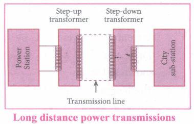
(ii) Since power produced is alternating in nature, there is a way out. The most important property of alternating voltage that it can be stepped up and stepped down by using transformers could be exploited in reducing current and thereby reducing power losses to a greater extent.
(iii) At the transmitting point, the voltage is increased and the corresponding current is decreased by using step-up transformer.
(iv) Then it is transmitted through transmission lines. This reduced current at high voltage reaches the destination without any appreciable loss.
Illustration:
An electric power of 2 MW is transmitted to a place through transmission lines of total resistance, say R = 40 Ω, at two different voltages. One is lower voltage (10 kV) and the other is higher (100 kV). Let us now calculate and compare power losses in these two cases.
Case (i):
\(P=2 \mathrm{MW} ; R=40 \Omega ; V=10 \mathrm{kV}\)
Power, P = V I
∴ Current, \(I=\frac{P}{V}=\frac{2 \times 10^6}{10 \times 10^3}=200 \mathrm{~A}\)
Power loss = Heat produced \(=\mathrm{I}^2 \mathrm{R}=(200)^2 \times 40=1.6 \times 10^6 \mathrm{~W}\)
\(% of power loss =\frac{1.6 \times 10^6}{2 \times 10^6} \times 100 \%\)\(\% of \ power \ loss =\frac{1.6 \times 10^6}{2 \times 10^6} \times 100 \%\)
\(=0.8 \times 100 \%=80 \%\)
Case (ii):
\(P=2 \mathrm{MW} ; R=40 \Omega ; V=100 \mathrm{kV} \)
\(\therefore \text {Current, } I=\frac{P}{V}=\frac{2 \times 10^5}{100 \times 10^3}=20 \mathrm{~A}\)
Power loss = PR= (20)2 x 40 = 0.016 x 10⁶ W
\(\% of \ power \ loss =\frac{0.01.6 \times 10^6}{2 \times 10^6} \times 100 \%\times 0.008 \%\times 100 \%=0.8\%\)
Thus, it is clear that when an electric power is transmitted at higher voltage, the power loss is reduced to a large extent.
16.
Principle:
The principle of transformer is the mutual induction between two coils. That is, when an electric current passing through a coil changes with time, an emf is induced in the neighbouring coil.
Construction:
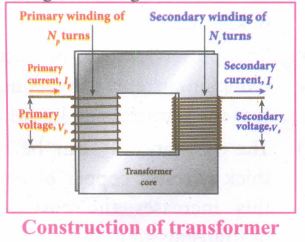
(i) In the simple construction of transformers, there are two coils of high mutual inductance wound over the same transformer core.
(ii) The core is generally laminated and is made up of a good magnetic material like silicon steel. Coils are electrically insulated but magnetically linked via transformer core.
(iii) The coil across which alternating voltage is applied is called primary coil P and the coil from which output power is drawn out is called secondary coil S. The assembled core and coils are kept in a container which is filled with suitable medium for better insulation and cooling purpose.
Working:
(i) If the primary coil is connected to a source of alternating voltage, an alternating magnetic flux is set up in the laminated core.
(ii) If there is no magnetic flux leakage, then whole of magnetic flux linked with primary coil is also linked with secondary coil.
(iii) This means that rate at which magnetic flux changes through each turn is same for both primary and secondary coils.
(iv) As a result of flux change, emf is induced in both primary and secondary coils. The emf induced in the primary coil vp or back of εp is given by,
vp = εp = -Np \(\frac{dФ_B}{dt}\) ........(1)
(vi) The frequency of alternating magnetic flux in the core is same as the frequency of the applied voltage. Therefore, induced emf in secondary will also have same frequency as that of applied voltage. The emf induced in the secondary coil εs is given by ,
εs = -Ns\(\frac{dФ_B}{dt}\)
Where Np and Ns are the number of turns in the primary and secondary coil respectively. If the secondary circuit is open, then εs = ሀs where u is the voltage ሀs across secondary coil
ሀs = εs = -Ns \(\frac{dФ_B}{dt}\) ........(2)
From equations (1) and (2),
\(\frac{v_s}{v_p}=\frac{N_s}{N_p}\) = K ........(3)
(vii) This constant K is known as voltage transformation ratio. For an ideal transformer, input power vpip= Output power vsis
where ip and is are the currents in the primary and secondary coil respectively.
(ix) Therefore,
\(\frac{V_s}{V_p}=\frac{N_s}{N_p}=\frac{I_p}{I_s}\) ........(4)
Equation (4) is written in terms of amplitude of corresponding quantities
\(\frac{V_s}{V_p}=\frac{N_s}{N_p}=\frac{I_p}{I_s}\) = K
i) If Ns> Np (or K > 1), ∴ Vs > Vp and Is < Ip This is the case of step-up transformer in which voltage is increased and the corresponding current is decreased.
ii) If Ns< Np (or K < 1), ∴ Vs < Vp and Is > Ip This is step-down transformer where voltage is decreased and the current is increased.
Efficiency of a transformer:
The efficiency η of a transformer is defined as the ratio of the useful output power to the input power. Thus,
\(η=\frac{Outpur \ power}{Input \ power}\times100% \) % ....(5)
17.
(a) Induction stove
(i) Induction stove is used to cook the food quickly and safely with less energy consumption. Below the cooking zone, there is a tightly wound coil of insulated wire.
(ii) The cooking pan made of suitable material, is placed over the cooking zone. When the stove is switched on, an alternating current flowing in the coil produces high frequency alternating magnetic field which induces very strong eddy currents in the cooking pan.
(iii) The eddy currents in the pan produce so much of heat due to Joule heating which is used to cook the food.
(b) Eddy current brake
(i) This eddy current braking system is generally used in high speed trains and roller coasters. Strong electromagnets are fixed just above the rails.
(ii) To stop the train, electromagnets are switched on. The magnetic field of these magnets induces eddy currents in the rails which oppose or resist the movement of the train. This is Eddy current linear brake.
(c) Eddy current testing
(i) It is one of the simple non-destructive testing methods to find defects like surface cracks, air bubbles present in a specimen.
(ii) A coil of insulated wire is given an alternating electric current, so that it produces an alternating magnetic field.
(iii) When this coil is brought near the test surface, eddy current is induced in the test surface.
(iv) The presence of defects causes the change in phase and amplitude of the eddy current that can be detected by some other means. In this way, the defects present in the specimen are identified.
(d) Electro magnetic damping:
(i) The armature of the galvanometer coil is wound on a soft iron cylinder.
(ii) Once the armature is deflected, the relative motion between the soft iron cylinder and the radial magnetic field induces eddy current in the cylinder.
(iii) The damping force due to the flow of eddy current brings the armature to rest immediately and then galvanometer shows a steady deflection. This is called electromagnetic damping.
18.
Predominantly Inductive
19.
Voltage leads current
20.
Voltage and current are in phase
21.
Law of conservation of energy
22.
Generator rule
23.
(b) Self Inductance
24.
(d) Power loss
25.
(d) None
26.
(a) I only

12th Standard Syllabus & Materials
12th Standard
TN 12th Computer Applications களப்பெயர் முறைமை (DNS) Sample Question Papers Study Material - QB365 Set A
NEW12th Standard
TN 12th Computer Applications வலையமைப்பு எடுத்துக்காட்டுகள் மற்றும் நெறிமுறைகள் Sample Question Papers Study Material - QB365 Set A
NEW12th Standard
TN 12th Computer Applications கணினி வலையமைப்பு ஓர் அறிமுகம் Sample Question Papers Study Material - QB365 Set A
NEW12th Standard
TN 12th Computer Applications PHP-உடன் MySQL-ஐ இணைத்தல் Sample Question Papers Study Material - QB365 Set A



Tamilnadu Stateboard 12th Standard Subjects

Maths

Chemistry
Physics

Biology

Computer Science

Business Maths and Statistics

Economics

Commerce

Accountancy

History

Computer Applications
Biology
Computer Technology
Computer Applications
Computer Science
Business Maths and Statistics
Commerce
Economics
Maths
Chemistry
Physics
Computer Technology
History
Accountancy

Tamil

English

French
Tamilnadu Stateboard Standards

