
 100% FREE ACCESS
12th Standard Syllabus & Materials
12th Standard
TN 12th Computer Applications மின்னணு தரவு பரிமாற்றம் Sample Question Papers Study Material - QB365 Set A
NEW12th Standard
TN 12th Computer Applications மின் - வணிக பாதுகாப்பு அமைப்புகள் Sample Question Papers Study Material - QB365 Set A
NEW12th Standard
TN 12th Computer Applications மின்னணு செலுத்தல் முறைகள் Sample Question Papers Study Material - QB365 Set A
NEW12th Standard
TN 12th Computer Applications மின் - வணிகம் Sample Question Papers Study Material - QB365 Set A
NEW12th Standard
TN 12th Computer Applications திறந்த மூல கருத்துருக்கள் Sample Question Papers Study Material - QB365 Set A
NEW12th Standard
TN 12th Computer Applications வலையமைப்பு வடமிடல் Sample Question Papers Study Material - QB365 Set A

Published on: 27/01/2021
12th Standard Physics English Medium Current Electricity Reduced Syllabus Important Questions 2021
Download Tamil Nadu 12th Standard Physics question papers, model tests, one-mark questions, important questions, and public exam papers in PDF format. Free study materials and answer keys for TN State Board students.
Questions + Answers key
Take MCQ Physics Test1.
Why are connecting resistors in a metre bridge made of thick copper strips?
2.
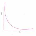
Plot a graph showing the variation of circuit I various resistance R connected to a cell of emf E and internal resistance r.
3.
When resistors are connected in parallel the effective resistance is reduced. Why?
4.
When resistors are connected in series the effective resistance is increased. Why?
5.
What is (i) thermoelectric current?
(ii) thermocouple?
6.
Define the term electric power and circuit its SI unit.
7.
Define resistance.
8.
Two cells each of 5V are connected in series with a 8 Ω resistor and three parallel resistors of 4 Ω, 6 Ω, and 12 Ω. Draw a circuit diagram for the above arrangement. Calculate
(i) the current drawn from the cells
(ii) current through each resistor
9.
What is Peltier effect?
10.
What is Seebeck effect?
11.
Define temperature coefficient of resistance.
12.
Compute the current in the wire if a charge of 120 C is flowing through a copper wire in 1 minute.
13.
Explain Peltier effect.
14.
Find the expression for the equivalent emf & internal resistance of the series combination of cells.
15.
In a circuit containing internal resistance r. Find the power delivered.
16.
Derive a relation between internal resisance and emf of a cell.
17.
What is meant by electromotive force?
18.
Three identical lamps each having a resistance R are connected to the battery of emf ε as shown in the figure.
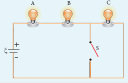
Suddenly the switch S is closed.
(a) Calculate the current in the circuit when S is open and closed
(b) What happens to the intensities of the bulbs A, B, and C.
(c) Calculate the voltage across the three bulbs when S is open and closed
(d) Calculate the power delivered to the circuit when S is opened and closed
(e) Does the power delivered to the circuit decrease, increase or remain same?
19.
In a Wheatstone’s bridge P = 100 Ω, Q = 1000 Ω and R = 40 Ω. If the galvanometer shows zero deflection, determine the value of S.
20.
Calculate the current that flows in the 1 Ω resistor in the following circuit.
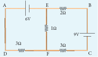
21.
The following figure shows a complex network of conductors which can be divided into two closed loops like EACE and ABCA. Apply Kirchoff’s voltage rule(KVR)
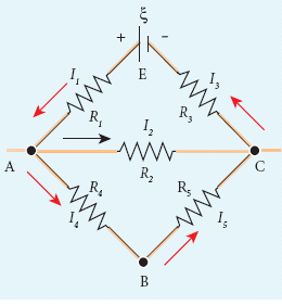
22.
From the given circuit,
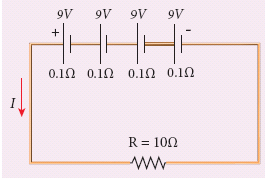
Find
i) Equivalent emf of the combination
ii) Equivalent internal resistance
iii) Total current
iv) Potential difference across external resistance
v) Potential difference across each cell
23.
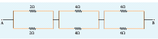
Calculate the equivalent resistance between A and B in the given circuit.
24.
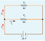
Calculate the equivalent resistance in the following circuit and also find the values of current I, I1 and I2 in the given circuit.
25.
In the case of Wheatstone's Bridge the bridge balance condition will be obtained only when____
the current through the galvanometer is maximum
the current through the galvanometer is minimum
the current through the galvanometer is zero
the current through the galvanometer is infinity
26.
Kirchhoff's I law is a consequence of__________
law of conservation of energy
law of conservation of charges
law of conservation of currents
law of conservation of voltages
27.
Kirchhoff's law is applicable only for__________
simple circuits
primary circuits
complicated circuits
secondary circuits
28.
The algebraic sum of the currents meeting at any junction in the circuit is_______
infinity
negative value
2A
zero
29.
When three resistors are connected in parallel then the value of the effective resistance is________
less than or equal to individual resistance
greater than or equal to individual resistance
less than the individual resistance
greater than the individual resistance
30.
When a current of 5 A flows through a conductor of resistance 3 \(\Omega \) the loss of power due to joule heating effect is_________
75 W
25 W
70.7 W
45 W
31.
A resistance of a metal wire of length AB is 2\(\Omega \). Another wire of length PQ of the same metal with twice the diameter of the wire AB is found to have the same resistance of 2\(\Omega \). What is the length of PQ?
4 AB
2 AB
1AB
6 AB
32.
Two identical resistors are connected in parallel then connected in series. The effective resistance are in the ratio ________________.
1:2
2:1
1:4
4:1
33.
The sensitivity of a potentiometer can be increased by ___________________.
decreasing the length of potentiometer wire
increasing the length of potentiometer wire
increasing the emf of the cell used in primary circuit
all the above
34.
Joules's heating effect is desirable in ___________________.
AC dynamo
DC dynamo
water heater
transformer
35.
Resistance increases with increases in temperature for _________________.
conductor
semiconductors
insulators
superconductor
36.
Kirchoff's I law i.e, \(\Sigma i=0\) at a junction, deals with the conservation of ______________.
charge
energy
momentum
angular momentum
37.
An unknown resistance is connected in parallel with a 15\(\Omega \) resistance and a 12V battery. What is the value of the unknown resistance if the current in the circuit is 2A?
\(10\Omega \)
\(20\Omega \)
\(30\Omega \)
\(40\Omega \)
38.
When 'n' resistors of equal resistance (R) are connected in series and in parallel respectively, then the ratio of their effective resistance is ______________
1: n2
n2: 1
n: 1
1: n
39.
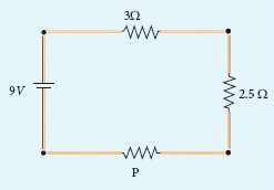
There is a current of 1.0 A in the circuit shown below. What is the resistance of P ?
1.5 Ω
2.5 Ω
3.5 Ω
4.5 Ω
40.
An aluminium wire of diameter 0.24 cm is connected in series to a copper wire of diameter 0.16 cm. The wires carry an electric current of 10 A. Determine the current density in aluminium wire.
41.
Calculate the effect internal resistance in series and parallel.
42.
Explain the determination of the internal resistance of a cell using voltmeter.
43.
Explain the equivalent resistance of a series and parallel resistor network.
1.
Thick copper strips offer minimum resistance and hence avoid the error due to end resistance. Which have not been taken into account in the bridge formula.
2.
\(I=\cfrac { E }{ R+r } \)
3.
When resistors are connected in parallel there is an effective increase in area. Since \(R\alpha \cfrac { 1 }{ A } \) resistance is reduced.
4.
When resistors are connected in series, there is an increase in the effective length. Since resistance varies directly proportional to the length the effective resistance increases \(R\ \alpha\ l\) .
5.
(i) The current that flows due to the emf developed in thermocouple is called thermoelectric current.
(ii) The two dissimilar metals connected to form two junctions is known a thermocouple.
6.
The electrical power P is the rate at which the electrical potential energy is delivered
\(P=\cfrac { dW }{ dt } =\cfrac { d }{ dt } \left( V.dQ \right) =V\cfrac { dQ }{ dt } \)
Since the electric current \(I=\cfrac { dQ }{ dt } \).
So the equation (1) can be rewritten as P = VI
This expression gives the power delivered by the battery to any electrical system, where I is the current passing through it and V is the potential difference across it. The SI unit of electrical power is a watt.
7.
The resistanct is defined as the ratio of potential difference across the given conductor to the current passing through the conductor.
\(R=\cfrac { V }{ I } \)
8.
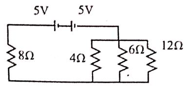
Circuit Diagram:
Here, 2 cells are in series,
\(\therefore \varepsilon_{\mathrm{tot}} =\varepsilon+\varepsilon=2 \varepsilon \)
\(\varepsilon_{\mathrm{tot}} =10 \mathrm{~V}\)
Here 4, 6 and 12 are in parallel
\(\therefore \frac{1}{\mathrm{R}_{\mathrm{p}}} =\frac{1}{\mathrm{R}_1}+\frac{1}{\mathrm{R}_1}+\frac{1}{\mathrm{R}_1}=\frac{1}{4}+\frac{1}{6}+\frac{1}{12} \)
\(\mathrm{R}_{\mathrm{p}} =2 \Omega\)
Now, the circuit becomes,
(i) current drawn from the cell (through the circuit) is,
\(\mathrm{I}=\frac{\mathrm{V}}{\mathrm{R}_{\mathrm{s}}}=\frac{10}{8+2}=1 \mathrm{~A}\)
Potential drop across the parallel combination of 3 resistors is \(\mathrm{V}^{\prime}=1 R_P=1 \times 2=2 \mathrm{~V}\)
(ii) Current through 8 resistor is I =1 A
\((\because 8 \Omega, 2 \Omega \text { in series) }\)
Current through \(\mathrm{R}=4 \Omega \ is, \mathrm{I}=\frac{\mathrm{V}^{\prime}}{\mathrm{R}}=\frac{2}{4}=0.5 \mathrm{~A}\)
Current through \(\mathrm{R}=6 \Omega \ is, \mathrm{I}=\frac{\mathrm{V}^1}{\mathrm{R}}=\frac{2}{6}=0.33 \mathrm{~A}\)
Current through \(\mathrm{R}=12 \Omega \ is, \mathrm{I}=\frac{\mathrm{V}^1}{\mathrm{R}}=\frac{2}{12}=0.17 \mathrm{~A}\)
9.
Peltier discovered that, when an electric current is passed through a circuit of a thermocouple heat is evolved at one junction and absorbed at the other junction. This is known as Peltier effect.
10.
Seebeck discovered that in a closed circuit consisting of two dissimilar metals, when the junctions are maintained at different temperature an emf is developed.
11.
Temperature coefficient of resistance is defined as the ratio of increase in resistivity per degree rise in temperature to its resistivity at To.
\(\alpha=\frac{\rho_{T}-\rho_{0}}{\rho_{0}\left(T-T_{0}\right)}\)
12.
The current (rate of flow of charge) in the wire is
\(I=\frac { Q }{ t } =\frac { 120 }{ 60 } =2A\)
13.
(i) When an electric current is passed through a circuit of a thermocouple, heat is evolved at one junction and absorbed at the other junction. This is known as the Peltier effect.
(ii) In the Cu-Fe thermocouple the junctions A and B are maintained at the same temperature.
(iii) Let a current from a battery flow through the thermocouple. At junction A, where the current flows from Cu to Fe, heat is absorbed and junction A becomes cold.
(iv) At junction B, where the current flows from Fe to Cu heat is liberated and it becomes hot.
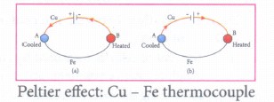
Peltier effect: Cu - Fe thermocouple
(v) When the direction of current is reversed, junction A gets heated and junction B gets cooled as shown in Figure (b).
Hence Peltier effect is reversible.
14.
(i) Suppose n cells, each of emf \(\xi \) volts and internal resistance r ohms are connected in series with an external resistance R.
(ii) The total emf of the battery = \(n\xi \) The total resistance in the circuit = nr + R By Ohm's law, the current in the circuit is
\(I=\cfrac { totalemf }{ taoal\ resistance } =\cfrac { n\xi }{ nr+R } \)
\(I=\cfrac { n\xi }{ R } =n{ l }_{ 1 }\)
(iii) where II is the current due to a single cell
\(\left( { I }_{ 1 }=\cfrac { \xi }{ R } \right) \)
Thus, if r is negligible when compared to R the current supplied by the battery is n times that supplied by a single cell.
Case (b) If r >> R,\(I=\cfrac { n\xi }{ nr } =\cfrac { \xi }{ r } \)
(iv) It is the current due to a single cell. That is, current due to the whole battery is the same as that due to a single cell and hence there is no advantage in connecting several cells.
(v) Thus series connection of cells is advantageous only when the effective internal resistance of the cells is negligibly small compared with R.
15.
(i) Due to this internal resistance, the power delivered to the circuit is not equal to power rating mentioned in the battery.
(ii) For a battery of emf \({ \xi }_{ 1 }\) with an internal resistance r, the power delivered to the circuit of resistance R is given by
\(P=I\xi =I(V+Ir)\)
Here V is the voltage drop across the resistance R and it is equal to IR.
Therefore, P = I (IR +Ir)
P = I2 R + I2 r
(iii) Here Pr is the power delivered to the internal resistance and PR is the power delivered to the electrical device (here it is the resistance R). For a good battery, the internal resistance r is very small, then for P < r < P
16.
(i) The emf of cell \(\xi \) is measured by connecting a high resistance voltmeter across it without connecting the external resistance R.
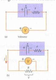
(ii) Since the voltmeter draws very little current for deflection, the circuit may be considered as open. Hence the voltmeter reading gives the emf of the cell.
(iii) Then, external resistance R is included in the circuit, and current I is established in the circuit. The potential difference across R is equal to the potential difference across the cell (V).
(iv) The potential drop across the resistor R is V + IR
(v) Due to internal resistance r of the cell, the voltmeter reads a value V, which is less than the emf of cell . It is because a certain amount of voltage (Ir) has dropped across the internal resistance r.
Then \(V=\xi -Ir\)
\(Ir=\xi -V\)
(vi) Dividing equation (2) by equation (1) we get
\(\cfrac { Ir }{ IR } =\cfrac { \xi -V }{ V } \)
\(r=\left| \cfrac { \xi -V }{ V } \right| R\)
Since \(\xi \) V and R are known, internal resistance r can be determined.
17.
A battery or cell is called a source of electromotive force (emf).
(i) The emf of a battery or cell is the voltage provided by the battery when no current flows in the external circuit.
(ii) Electromotive force determines the amount of work a battery or cell does to move a certain amount of charge around the circuit. It is denoted by the symbol and to be pronounced as 'xi'. An ideal battery has zero internal resistance and the potential difference (terminal voltage) across the battery equals to its emf.
(iii) A real battery is made of electrodes and electrolyte, there is resistance to the flow of charges within the battery. This resistance is called internal resistance r. For a real battery, the terminal voltage is not equal to the emf of the battery. A freshly prepared cell has low internal resistance and it increases with ageing.
18.
| Electrical quantities | Switch S is open | Switch S is closed |
| (a) Current | \(\frac { \varepsilon}{ 3R } \) | \(\frac { \varepsilon }{ 2R } \) |
| (b) Intensity | All the bulbs glow with equal intensity. | The intensities of the bulbs A and B equally increase. Bulb C will not glow since no current pass through it. |
| (c) Voltage | \({ V }_{ A }=\frac {\varepsilon }{ 3 } ,\) \({ V }_{ B }=\frac { \varepsilon }{ 3 } ,\) \({ V }_{ C }=\frac { \varepsilon }{ 3 } \) |
\({ V }_{ A }=\frac { \varepsilon }{ 2 } ,\) \({ V }_{ B }=\frac { \varepsilon }{ 2 } ,\) Vc= 0 |
| (d) Power | \(P_{ A }=\frac { {\varepsilon }^{ 2 } }{ 9R } ,\) \({ P }_{ B }=\frac { { \varepsilon }^{ 2 } }{ 9R } ,\) \({ P }_{ C }=\frac { { \varepsilon }^{ 2 } }{ 9R } \) |
\(P_{ A }=\frac { { \varepsilon }^{ 2 } }{ 4R } ,\) \({ P }_{ B }=\frac { {\varepsilon }^{ 2 } }{ 4R } ,\) Pc=0 |
| (e) Total power delivered to the circuit increases. | ||
19.
\(\frac { P }{ Q } =\frac { R }{ S } \)
\(S=\frac { Q }{ P } \times R\)
\(S=\frac { 1000 }{ 100 } \times 40S=400\Omega \)
20.
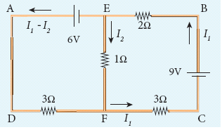
We can denote the current that flows from 9V battery as I1 and it splits up nto I2 and (I1 – I2) at the junction E according Kirchoff’s current rule (KCR).
Now consider the loop EFCBE and apply KVR, we get
1I2 + 3I1 + 2I1 = 9
5I1 + I2 = 9 (1)
Applying KVR to the loop EADFE, we get
3 (I1 – I2 ) – 1I2 = 6
3I1 – 4I2 = 6 (2)
Solving equation (1) and (2), we get
I1 = 1.83 A and I2 = -0.13 A
It implies that the current in the 1 ohm resistor flows from F to E.
21.
Thus applying Kirchoff’s second law to the closed loop EACE
I1R1 + I2R2 + I3R3 = ξ
and for the closed loop ABCA
I4R4 + I5R5 - I2R2 = 0
22.
Equivalent emf of the combination
ξeq = nξ = 4 x 9 = 36 V
ii) Equivalent internal resistance req = nr = 4 x 0.1 = 0.4 Ω
iii) Total current \(I=\frac { n\xi }{ R+nr } \)
\(=\frac { 4\times 9 }{ 10+(4\times 0.1) } \)
\(=\frac { 4\times 9 }{ 10+0.4 } =\frac { 36 }{ 10.4 } \)
I = 3.46 A
iv) Potential difference across external resistance V = IR = 3.46 x 10 = 34.6 V. The remaining 1.4 V is dropped across the internal resistance of cells.
v) Potential difference across each cell \(\frac { V }{ n } =\frac { 34.6 }{ 4 } =8.65V\)
23.
In all the sections, the resistors are connected in parallel.
Section I
\(\frac { 1 }{ { R }_{ { P }_{ 1 } } } =\frac { 1 }{ { R }_{ 1 } } +\frac { 1 }{ { R }_{ 2 } } \)
\(\frac { 1 }{ { R }_{ { P }_{ 1 } } } =\frac { 1 }{ 2 } +\frac { 1 }{ 2 } =\frac { 2 }{ 2 } \quad { R }_{ { p }_{ 1 } }=1\Omega \)
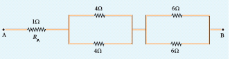
Section II
\(\frac { 1 }{ { R }_{ { P }_{ 1 } } } =\frac { 1 }{ 4 } +\frac { 1 }{ 4 } =\frac { 2 }{ 4 } ,\quad \frac { 1 }{ { R }_{ { P }_{ 2 } } } =\frac { 1 }{ 2 } ,{ R }_{ { p }_{ 2 } }=2\Omega \)
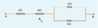
Section III
\(\frac { 1 }{ { R }_{ { P }_{ 3 } } } =\frac { 1 }{ 6 } +\frac { 1 }{ 6 } =\frac { 2 }{ 6 } \)
\(\frac { 1 }{ { R }_{ { P }_{ 3 } } } =\frac { 1 }{ 3 } ,{ R }_{ { p }_{ 3 } }=3\Omega \)
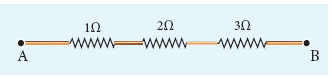
Equivalent resistance is given by
R = Rp1 + Rp2 + Rp3
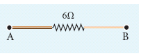
R = 1 Ω + 2 Ω + 3 Ω = 6 Ω
The circuit became,
Equivalent resistance between A and B is
24.
Since the resistances are connected in parallel, therefore, the equivalent resistance in the circuit is
\(\frac { 1 }{ { R }_{ p } } =\frac { 1 }{ { R }_{ 1 } } +\frac { 1 }{ { R }_{ 2 } } =\frac { 1 }{ 4 } +\frac { 1 }{ 6 } \)
\(\frac { 1 }{ { R }_{ p } } =\frac { 5 }{ 12 } \Omega \quad or\quad { R }_{ p }=\frac { 12 }{ 5 } \Omega \)
The resistors are connected in parallel, the potential difference (voltage) across them is the same.
\({ I }_{ 1 }=\frac { V }{ { R }_{ 1 } } =\frac { 24V }{ 4\Omega } =6A\)
\({ I }_{ 2 }=\frac { V }{ { R }_{ 2 } } =\frac { 24 }{ 6 } =4A\)
The current I is the sum of the currents in the two branches. Then,
I = I1 + I2 = 6 A + 4 A = 10 A
25.
(c)
the current through the galvanometer is zero
26.
(b)
law of conservation of charges
27.
(c)
complicated circuits
28.
(c)
2A
29.
(c)
less than the individual resistance
30.
(a)
75 W
31.
(a)
4 AB
32.
(a)
1:2
33.
(b)
increasing the length of potentiometer wire
34.
(c)
water heater
35.
(a)
conductor
36.
(a)
charge
37.
(a)
\(10\Omega \)
38.
(b)
n2: 1
39.
Rs = 3 + 2.5 + P = 5.5 + P
V = 9 V, I = 1.0 A
Rs = \(\frac{V}{I}=\frac{9}{1}= 9 \Omega\)
∴ 9 = 5.5 + P
∴ P = 9 - 5.5 = 3.5 Ω
40.
Diameter d 0.24 cm = 0.24 x 10⁻² m
radius \(r=\cfrac { d }{ 2 } =0.12\times { 1 }^{ -2 }m\)
Current, I = 10A
Current density \(J=\cfrac { 1 }{ A } =\cfrac { 1 }{ { \pi r }^{ 2 } } \)
= \(\cfrac { 10 }{ 3.14\times \left( 0.12\times { 10 }^{ -2 } \right) ^{ 2 } } \)
= 2.2 x 10⁶ Am-2
41.
(i) Suppose n cells, each of emf volts and internal resistance r ohms are connected in series with an external resistance R as shown in Figure
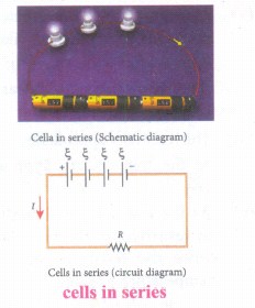
(ii) The total emf of the battery = nr
The total resistance in the circuit = nr + R
By Ohm's law, the current in the circuit is
\(I=\cfrac { total\ emf }{ total\ resistance } =\cfrac { n\xi }{ nr+5 } \)
Case (a) If r << R, then
\(I=\cfrac { n\xi }{ R } ={ nl }_{ 1 }\)
where II is the current due to a single cell
\(\left( { I }_{ 1 }=\cfrac { \xi }{ R } \right) \)
(iii) Thus, if r is negligible when compared to R the current supplied by the battery is n times that supplied by a single cell
Case (b) If >> R, \(I=\cfrac { n\xi }{ nr } =\cfrac { \xi }{ r } \)
(iv) It is the current due to a single cell. That is, current due to the whole battery is the same as that due to a single cell and hence there is no advantage in connecting several cells.
(v) Thus series connection of cells is advantageous only when the effective internal resistance of the cells is negligibly small compared with R. Cells in parallel
(i) In parallel connection all the positive terminals of the cells are connected to one point and all the negative terminals to a second point. These two points form the positive and negative terminals of the battery.
(ii) Let n cells be connected in parallel between the points A and B and a resistance R is connected between the points A and B as shown in Figure. Let be the emf and r the internal resistance of each cell.
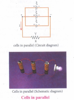
(iii) The equivalent internal resistance of the battery is \(\cfrac { 1 }{ { { r }_{ eq } } } =\cfrac { 1 }{ r } +\cfrac { 1 }{ r } +...\cfrac { 1 }{ r } (netrms)=\cfrac { n }{ r } \)
So \(\cfrac { 1 }{ { r }_{ eq } } =\cfrac { r }{ n } \) and the total resistance in the circuit = \(R+\cfrac { r }{ n } \) The total emf is the potential difference between the points A and B, which is equal to \(\xi \) The current in the circuit is given by
\(I=\cfrac { \xi }{ \frac { r }{ n } +R } \)
\(I=\cfrac { n\xi }{ r+nR } \)
Case (a) If >> R,\(I=\cfrac { n\xi }{ r } ={ nl }_{ 1 }\)
Case (b) If < \(I=\cfrac { \xi }{ R } \)
where II is the current due to a single cell and is equal to \(\cfrac { \xi }{ r } \) when R is negligible. Thus, the current through the external resistance due to the whole battery is n times the current due to a single cell.
42.
(i) The emf of cell ε is measured by connecting a high resistance voltmeter across it without connecting the external resistance R.
(ii) Since the voltmeter draws very little current for deflection, the circuit may be considered as open.
(iii) Hence the voltmeter reading gives the emf of the cell.
(iv) Then, external resistance R is included in the circuit and current I is established in the circuit.
(v) The potential difference across R is equal to the potential difference across the cell V.
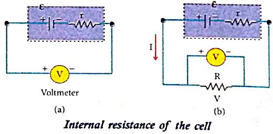
(vi) The potential drop across the resistor R is,
v = IR .........(1)
(vii) Due to internal resistance r of the cell, the voltmeter reads a value V, which is less than the emf of cell ε. It is because, certain amount of voltage (Ir) has dropped across the internal resistance r.
Then V = \(\varepsilon\) - Ir
Ir = \(\varepsilon\) - v ......(2)
(viii) Dividing equation (2) by equation (1), we get
\(\frac{I r}{I R}=\frac{\varepsilon-V}{V} \)
\(r=\left|\frac{\varepsilon-V}{V}\right| R \)
(ix) Since \(\varepsilon\), V and R are known, internal resistance r can be determined.
43.
Resistors in series:
(i) When two or more resistors are connected end to end, they are said to be in series. The resistors could be simple resistors or bulbs or heating elements or other devices. Figure (a) shows three resistors R1, R2 and R3 connected in series.
(ii) The amount of charge passing through resistor R1 must also pass through resistors R2 and R3 since the charges cannot accumulate anywhere in the circuit. Due to this reason, the current I passing through all the three resistors are the same.
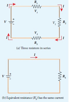
(iii) According to Ohm's law, if same current pass through different resistors of different values, then the potential difference across each resistor must be different. Let V1, V2 and V3 be the potential difference (voltage)across each of the resistors R1, R2 and R3 respectively, then we can write V1 = IR1, V2= RI2 and V3 = IR3. But the total voltage V is equal to the sum of voltages across each resistor.
V = V1 + V2 + V3 = IR1+ IR2 + IR3
V = I (R1 + R2 + R3)
V = IRS
where Rs is the equivalent resistance,
RS = R1 + R2 + R3
(iv) When several resistances are connected in series, the total or equivalent resistance is the sum of the individual resistances.
Note: The value of equivalent resistance in series connection will be greater than each individual resistance.
Resistors in parallel:
(i) Resistors are in parallel when they are connected across the same potential difference as shown in figure (a).
(ii) In this case, the total current I that leave the battery split into three separate components.
Let I1, I2 and I3 be the current through the resistors R1, R2, and R3 respectively. Due to the conservation of charge, total current in the circuit I is equal to sum of the currents through each of the three resistors.
I = I1 + I2 + I3 .....(1)
(iii) Since the voltage across each resistor is the same, applying Ohm's law to each resistor, we have
\({ I }_{ 1 }=\cfrac { V }{ { R }_{ 1 } } ,{ I }_{ 2 }=\cfrac { V }{ { R }_{ 2 } } ,{ I }_{ 3 }=\cfrac { V }{ { R }_{ 3 } } \)
Substituting these values in equation (1), we get,
\({ I }_{ 1 }=\cfrac { V }{ { R }_{ 1 } } +\cfrac { V }{ { R }_{ 2 } } +\cfrac { V }{ { R }_{ 3 } } =V\left[ \cfrac { 1 }{ { R }_{ 1 } } +\cfrac { 1 }{ { R }_{ 2 } } +\cfrac { 1 }{ { R }_{ 3 } } \right] \)
\(I=\cfrac { V }{ { R }_{ p } } \)
\(\cfrac { 1 }{ R_{ P } } =\cfrac { 1 }{ { R }_{ 1 } } +\cfrac { 1 }{ { R_{ 2 } } } +\cfrac { 1 }{ R_{ 3 } } \)
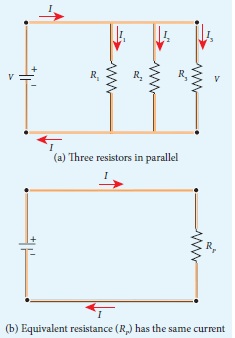
Here RP is the equivalent resistance of the parallel combination of the resistors. Thus, when a number of resistors are connected in parallel, the sum of the reciprocal of the values of resistance of the individual resistor is equal to the reciprocal of the effective resistance of the combination.
Note: The value of equivalent resistance in parallel connection will be lesser than each individual resistance.

12th Standard Syllabus & Materials
12th Standard
TN 12th Computer Applications களப்பெயர் முறைமை (DNS) Sample Question Papers Study Material - QB365 Set A
NEW12th Standard
TN 12th Computer Applications வலையமைப்பு எடுத்துக்காட்டுகள் மற்றும் நெறிமுறைகள் Sample Question Papers Study Material - QB365 Set A
NEW12th Standard
TN 12th Computer Applications கணினி வலையமைப்பு ஓர் அறிமுகம் Sample Question Papers Study Material - QB365 Set A
NEW12th Standard
TN 12th Computer Applications PHP-உடன் MySQL-ஐ இணைத்தல் Sample Question Papers Study Material - QB365 Set A



Tamilnadu Stateboard 12th Standard Subjects

Maths

Chemistry
Physics

Biology

Computer Science

Business Maths and Statistics

Economics

Commerce

Accountancy

History

Computer Applications
Biology
Computer Technology
Computer Applications
Computer Science
Business Maths and Statistics
Commerce
Economics
Maths
Chemistry
Physics
Computer Technology
History
Accountancy

Tamil

English

French
Tamilnadu Stateboard Standards

