
 100% FREE ACCESS
12th Standard Syllabus & Materials
12th Standard
TN 12th Computer Applications மின்னணு தரவு பரிமாற்றம் Sample Question Papers Study Material - QB365 Set A
NEW12th Standard
TN 12th Computer Applications மின் - வணிக பாதுகாப்பு அமைப்புகள் Sample Question Papers Study Material - QB365 Set A
NEW12th Standard
TN 12th Computer Applications மின்னணு செலுத்தல் முறைகள் Sample Question Papers Study Material - QB365 Set A
NEW12th Standard
TN 12th Computer Applications மின் - வணிகம் Sample Question Papers Study Material - QB365 Set A
NEW12th Standard
TN 12th Computer Applications திறந்த மூல கருத்துருக்கள் Sample Question Papers Study Material - QB365 Set A
NEW12th Standard
TN 12th Computer Applications வலையமைப்பு வடமிடல் Sample Question Papers Study Material - QB365 Set A

Published on: 02/09/2022
QB365 provides a detailed and simple solution for every Possible Book Back Questions in Class 12 Physics Subject - Retirement and Death of a Partner, English Medium. It will help Students to get more practice questions, Students can Practice these question papers in addition to score best marks.
Download Tamil Nadu 12th Standard Physics question papers, model tests, one-mark questions, important questions, and public exam papers in PDF format. Free study materials and answer keys for TN State Board students.
Questions + Answers key
Take MCQ Physics Test1.
Describe briefly Davisson – Germer experiment which demonstrated the wave nature of electrons.
2.
Briefly explain the principle and working of electron microscope.
3.
4.
Explain experimentally observed facts of photoelectric effect with the help of Einstein’s explanation.
5.
Obtain Einstein’s photoelectric equation with necessary explanation.
6.
Give the quantum concept of energy proposed by Max Planck.
7.
Explain how frequency of incident light varies with stopping potential.
8.
Explain the effect of potential difference on photoelectric current.
9.
Briefly discuss the observations of Hertz, Hallwachs and Lenard.
10.
What do you mean by electron emission? Explain briefly various methods of electron emission.
11.
Derive an expression for de Broglie wavelength of electrons.
12.
Explain why photoelectric effect cannot be explained on the basis of wave nature of light.
1.
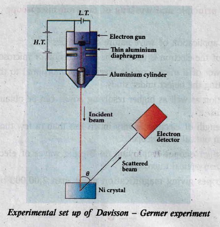
Davisson - Germer experiment
(i) The filament F is heated by a low tension (L . T) battery. Electrons are emitted from the hot filament by thermionic emission.
(ii) They are then accelerated due to the potential diference between the filament and the anode aluminum cylinder by a high tension (H.T) battery.
(iii) Electron beam is collimated by using two thin aluminum diaphragms and is allowed to strike a single crystal of Nickel.
(iv) The electrons scattered by Niatoms in diflerent directions are received by the electron detector which measures the intensity of scattered electron beam.
(v) The detector is capable of rotation in the plane of the paper, so that the angle (\(\theta\)) between the incident beam and the scattered beam can be changed at our will.
(vi) The intensity of the scattered electron beam is measured as a function of the angle \(\theta\).
(i) Figure shows the variation of intensity of the scattered electrons with the angle \(\theta\) for the accelerating voltage of 54 V.
(ii) For a given accelerating voltage V, the scattered wave shows a peak or maximum at an angle of 50o to the incident electron beam.
(iii) This peak in intensity is attributed to the constructive interference of electrons diffracted from various atomic layers of the target material.
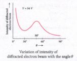
(iv) From the known value of interplanar spacing of Nickel, the wavelength of the electron wave has been experimentally calculated as 1.65\(\overset { o }{ A }\).
(v) The wavelength can also be calculated from de Broglie relation for V = 54 V from equation as
\(\lambda =\cfrac { 12.27 }{ \sqrt { V } } \overset { o }{ A } =\cfrac { 12.27 }{ \sqrt { 54 } } \)
\(\lambda =1.67\overset { o }{ A } \)
(vi) This value agrees very well with the experimentally observed wavelength of 1.65 \(\overset { o }{ A }\). Thus this experiment directly verifies de Broglie's hypothesis of the wave nature of moving particles.
2.
Principle:
(i) The wave nature of the electron is used in the construction of microscope called electron microscope.
(ii)The resolving power of a microscope is inversely proportional to the wavelength of the radiation used for illuminating the object under study.
(iii) Higher magnification as well as higher resolving power can be obtained by employing the waves of shorter wavelengths.
(iv) De Broglie's wavelength of electron is very much less than (a few thousand less) that of the visible light being used in optical microscopes.
(v) As a result, the microscopes employing de Broglie waves of electrons have very much higher resolving power than optical microscope.
(vi) Electron microscopes giving magnification more than 2,00,000 times are common in research laboratories.
Working:
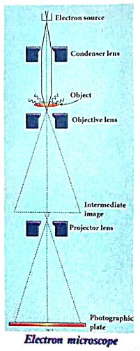
(i) The construction and working of an electron microscope is similar to that of an optical microscope except that in electron microscope focussing of electron beam is done by the electrostatic or magnetic lenses.
(ii) The electron beam passing across a suitably arranged either electric or magnetic fields undergoes divergence or convergence thereby focussing of the beam is done.
(iii) The electrons emitted from the source are accelerated by high potentials.
(iv) The beam is made parallel by magnetic condenser lens; When the beam passes through the sample whose magnified image is needed, the beam carries the image of the sample.
(v) With the help of magnetic objective lens and magnetic projector lens system, the magnified image is obtained on the screen. These electron microscopes are being used in almost all brands of science.
3.
4.
Explanation for the photoelectric effect:
The experimentally observed facts of photoelectric effect can be explained with the help of Einstein's photoelectric equation.
(i) As each incident photon liberates one electron, then the increase of intensity of the light (the number of photons per unit area per unit time) increases the number of electrons emitted thereby increasing the photocurrent. The same has been experimentally observed.
(ii) From Kmax = hv - Φ0, it is evident that Kmax is proportional to the frequency of the light and is independent of intensity of the light.
(iii) As given in equation \({ hv }_{ o }+\cfrac { 1 }{ 2 } { mv }^{ 2 }\) , there must be minimum energy (equal to the work function of the metal) for incident photons to liberate electrons from the metal surface. Below which, emission of electrons is not possible. Correspondingly, there exists minimum frequency called threshold frequency below which there is no photoelectric emission.
(iv) According to quantum concept, the transfer of photon energy to the electrons is instantaneous so that there is no time lag between incidence of photons and ejection of electrons.
Thus, the photoelectric effect is explained on the basis of quantum concept of light.
5.
(i) When a photon of energy hv is incident on a metal surface, it is completely absorbed by a single electron and the electron is ejected.
(ii) In this process, a part of the photon energy is used for the ejection of the electrons from the metal surface (photoelectric work function Φ0) and the remaining energy as the kinetic energy of the ejected electron. From the law of conservation of energy,
\(\\ \\ \\ hv=\phi { _{ 0 }+\cfrac { 1 }{ 2 } { mv }^{ 2 } }\) ......(1)
(iii) where m is the mass of the electron and v its velocity.
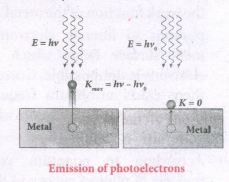
(iv) If we reduce the frequency of the incident light is reduced, the speed or kinetic energy of photo electrons is also reduced. At some frequency v0 of incident radiation, the photo electrons are ejected with almost zero kinetic energy.
Then the equation becomes.
\({ hv }_{ 0 }=\phi _{ 0 }\) ......(2)
(v) Where v0 is the threshold frequency. B rewriting the equation, we get
\(hv={ hv }_{ o }+\cfrac { 1 }{ 2 } { { mv }^{ 2 } }\) ......(3)
The equation is known as einstein's photoelectric equation.
(vi) If the electron does not lose energy by internal collisions, then it is emitted with maximum kinetic energy Kmax. Then
\({ K }_{ max }=\cfrac { 1 }{ 2 } { mv }^{ 2 }_{ max }\) ......(4)
(vii) where vmaxis the maximum velocity of max the electron ejected. The equation (1) is rearranged as follows:
\({ K }_{ max }=hv-{ \phi }_{ 0 }\)
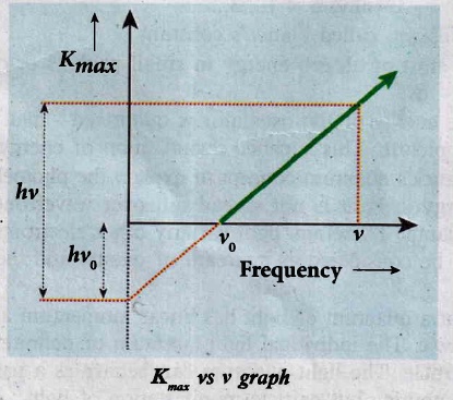
A graph between maximum kinetic energy Kmax of the photoelectron and frequency v of the incident light is a straight line.
6.
According to Planck, matter is composed of a large number of oscillating particles (atoms) which vibrate with different frequencies. Each atomic oscillator - which vibrates with its characteristic frequency - emits or absorbs electromagnetic radiation of the same frequency. It also says that.
(i) If an oscillator vibrates with frequency v, its energy can have only certain discrete values, given by the equation.
En= nhv; n = 1,2, 3
where h is a constant, called Planck's constant.
(ii) The oscillators emit or absorb energy in small packets or quanta and the energy of each quantum is E = hv.
This implies that the energy of the oscillator is quantized - that is, energy is not continuous as believed in the wave picture. This is called quantization of energy.
Einstein extended Planck's quantum concept to explain the photoelectric effect in 1905. According to Einstein, the energy in light is not spread out over wavefronts but is concentrated in small packets or energy quanta. Therefore, light (or any other electromagnetic waves) of frequency hv from any source can be considered as a stream of quanta and the energy of each light quantum is given by E = hv.
He also proposed that a quantum of .light has linear momentum and the magnitude of that linear momentum is P = hv/C. The individual light quantum of definite energy and momentum can be associated with a particle. The light quantum can behave as a particle and this is called photon. Therefore photon is nothing but particle manifestation of light.
7.
(i) To study the effect of frequency of incident light on stopping potential, the intensity of the incident light is kept constant.
(ii) The variation of photocurrent with the collector electrode potential is studied for radiations of different frequencies and a graph drawn between them is shown in Figure From the graph, it is clear that stopping potential vary over different frequencies of incident light.
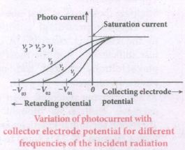
(iii) Greater the frequency of the incident radiation, larger is the corresponding stopping potential.
(iv) This implies that as the frequency is increased, the photoelectrons are emitted with greater kinetic energies so that the retarding potential needed to stop the photoelectrons is also greater.
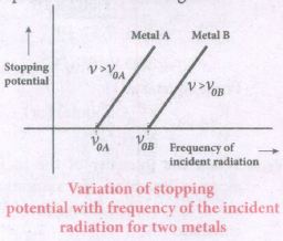
(v) Now a graph is drawn between frequent and the stopping potential for different metals (Figure).
(vi) From this graph, it is found that stopping potential varies linearly with frequency.
(vii) Below a certain frequency called their old quest no electrons are emitted; hence stopping potential is zero for that reason.
(viii) But as the frequency is increased above a threshold value, the stopping potential varies linearly with the frequency of incident light.
8.
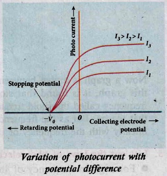
(i) To study the effect of potential difference V between the electrodes on photoelectric current, the frequency and intensity of the incident light are kept constant. Initially the potential of A is kept positive with respect to C and the cathode is irradiated with the given light.
(ii) As the potential of A is increased, photocurrent is also increased. However a stage is reached where photo current reaches a saturation value (saturation current) at which all the photoelectrons from C are collected by A.
(iii) This is represented by the flat portion of the graph between potential of A and photocurrent.
(iv) When a negative (retarding) potential is applied to A with respect to C, the current does not immediately drop to zero because the photoelectrons are emitted with some definite and different kinetic energies.
(vi) The kinetic energy of some of the photoelectrons is such that they could overcome the retarding electric field and reach the electrode A.
(vii) When the negative (retarding) potential of A is gradually increased, the photo current starts to decrease because more and more photoelectrons are being repelled away from reaching the electrode A. The photocurrent becomes zero at a particular negative potential Vo' called stopping or cut-off potential.
(viii) Stopping potential is that the value of the negative (retarding) potential given to the collecting electrode A which is just sufficient to stop the most energetic photoelectrons emitted and make the photocurrent zero.
(ix) At the stopping potential, even the most energetic electron is brought to rest. Therefore, the initial kinetic energy of the fastest electron (Kmax ) is equal to the work max done by the stopping potential to stop it (eVo).
\({ K }_{ max }=\cfrac { 1 }{ 2 } { mv }_{ max }^{ 2 }={ ev }_{ o }\)
\({ v }_{ max }=\sqrt { \cfrac { { 2eV }_{ o } }{ m } } \)
vmax = \(5.93\times { 10 }^{ 5 }\sqrt { { V }_{ o } } \)
(xi) From the Figure , When the intensity of the incident light alone is increased, the saturation current also increases but the value of Vo remains constant.
(xii) Thus, for a given frequency of the incident light, the stopping potential is independent of intensity of the incident light.
(xiii) This also implies that the maximum kinetic energy of the photoelectrons is independent of intensity of the incident light.
9.
Hertz observation:
(i) Maxwell's theory of electromagnetism predicted the existence of electromagnetic waves and concluded that light itself is just an electromagnetic wave. Then, the experimentalists tried to generate and detect electromagnetic waves through various experiments.
(ii) In 1887, Heinrich Hertz first became successful in generating and detecting electromagnetic wave with his high voltage spark discharge between two metallic spheres.
(iii) When a spark is formed, the charges will oscillate back and forth rapidly and the electromagnetic waves are produced.
(iv) The electromagnetic waves thus produced were detected by a detector that has a copper wire bent in the shape of a circle.
(v) Although the detection of waves is successful, there is a problem in observing the tiny spark produced in the detector.
(vi) In order to improve the visibility of the spark, Hertz made many attempts and finally noticed an important thing that small detector spark became more vigorous when it was exposed to ultraviolet light.
(vii) The reason for this behavior of the spark was not known at that time. Later it was found that it is due to the photoelectric emission. whenever ultraviolet light is incident on the metallic sphere, the electrons on the outer surface are emitted which caused the spark to be more vigorous.
Hallwachs' observation:
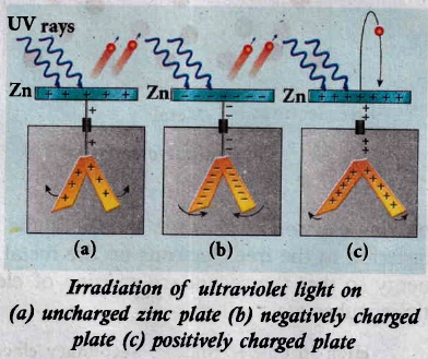
(i) In 1888, Wilhelm Hallwachs, a German physicist, confirmed that the strange behaviour of the spark is due to the action of ultraviolet light with his simple experiment.
(ii) A clean circular plate of zinc is mounted on an insulating stand and is attached to a gold leaf electroscope by a wire.
(iii) When the uncharged zinc plate is irradiated by ultraviolet light from an arc lamp, it becomes positively charged and the leaves will open.
(iv) Further, if the negatively charged zinc plate is exposed to ultraviolet light, the leaves will close as the charges leaked away quickly.
(v) If the plate is positively charged, it becomes more positive upon UV rays irradiation and the leaves will open further.
(vi) From these observations, it was concluded that negatively charged electrons were emitted from the zinc plate under the action of ultraviolet light.
Lenard's observation:
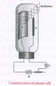
(i) ln 1902, Lenard studied this electron emission phenomenon in detail. His simple experimental setup is as shown in Figure.
(ii) The apparatus consists of two metallic plates A and C placed in an evacuated quartz bulb. The galvanometer G and battery B are connected in the circuit.
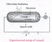
(iii) When ultraviolet light is incident on the negative plate C, an electric current flows in the circuit that is indicated by the deflection in the galvanometer.
(iv) On other hand, if the positive plate is irradiated by the ultraviolet light, no current is observed in the circuit.
(v) From these observations, it is concluded that when ultraviolet light falls on the negative plate, electrons are ejected from it which are attracted by the positive plate A.
(vi) On reaching the positive plate through the evacuated bulb, the circuit is completed and the current flows in it.
(vii) Thus, the ultraviolet light falling on the negative plate causes the electron emission from the surface of the plate.
10.
(i) In metals, the electrons in the outer most shells are loosely bound to the nucleus. Even at room temperature, there are a large number of free electrons which are moving inside the metal in a random manner. Through they move freely inside the metal they cannot leave the surface of the metal. The reason is that when free electrons reach the surface of the metal they are attracted by the positive nuclei of the metal. It is attractive pull which will not allow free electrons to leave the metallic surface at room temperature.
(ii) In order to leave the metallic surface, the free electrons must cross a potential barrier created by the positive nuclei of the metal. The potential barrier. which prevents free electrons from leading the metallic surface is called surface barrier.
(iii) Whenever an additional energy is given to the free electrons, they will have sufficient energy to cross the surface barrier. And they escape from the metallic surface. The liberation of electrons from any surface of a substance is called electron emission.
(iv) The minimum energy needed for an electron to escape from the metal surface is called work function of that metal.
(a) Thermionic emission
(i) When a metal is heated to a high temperature, the free electrons on the surface of the metal get sufficient energy in the form of thermal energy so that they are emitted from the metallic surface. This type of emission is known a thermonic emission.
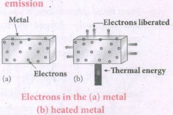
(ii) The intensity of the thermionic emission (the number of electrons emitted) depends on the metal used and its temperature.
(iii) Examples: cathode ray tubes, electron microscopes, X-ray tubes etc.
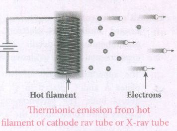
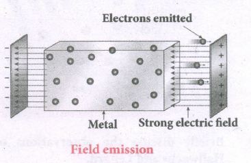
(b) Field emission
(i) Electric field emission occurs when a very strong electric field is applied across the metal.
(ii) This strong field pulls the free electrons and helps them to overcome the surface barrier of the metal.
(iii) Ex: Field ermssion scanning electron microscopes, Field-emission display etc.
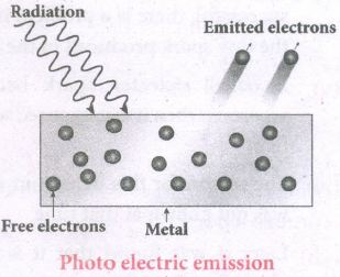
(c) Photo electric emission
(i) When an electromagnetic radiation of suitable frequency is incident on the surface of the metal, the energy is transferred from the radiation to the free electrons.
(ii) Hence, the free electrons get sufficient energy to cross the surface barrier and the photo electric emission takes place.
(iii) The number of electrons emitted depend on the intensity of the incident radiation.
(iv) Examples: Photo diodes, photo electric cells etc.
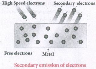
(d) Secondary emission
(i) When a beam of fast-moving electrons strikes the surface of the metal, the kinetic energy of the striking electrons is transferred to the free electrons on the metal surface.
(ii) Thus the free electrons get sufficient kinetic energy so that the secondary emission of electron occurs.
(iii) Examples: Image intensifiers, photo multiplier tubes etc.
11.
(i) An electron of mass m is accelerated through a potential difference of V volt. The kinetic energy acquired by the electron is given by
\(\cfrac { 1 }{ 2 } { mv }^{ 2 }=ev\)
(ii) Therefore, the speed v of the electron is
\(v=\sqrt { \cfrac { 2ev }{ m } } \)
Hence, the de Broglie wavelength of the matter waves associated with electron is
\(\lambda =\cfrac { h }{ mv } =\cfrac { h }{ \sqrt { 2mev } } \)
(iii) Substituting the known values in the above equation, we get
\(\lambda =\cfrac { 6.26\times { 10 }^{ -34 } }{ \sqrt { 2V\times 1.6\times { 10 }^{ -19 }\times 9.11\times { 10 }^{ -31 } } } \)
= \(\cfrac { 12.27\times { 10 }^{ -10 } }{ \sqrt { V } } m\)
\(\lambda =\cfrac { 12.27 }{ \sqrt { V } } \overset { o }{ A } \)
(iv) Since the kinetic energy of the electron, K = eV, then the de Broglie wavelength associated with electron can be also written as
\(\lambda =\cfrac { h }{ \sqrt { 2mK } } \)
12.
From Maxwell's theory we learnt that light is an electromagnetic wave consisting of coupled electric and magnetic oscillations that move with the speed of light and exhibit typical wave behaviour. Let us try to explain the experimental observations of photoelectric effect using wave picture of light.
(i) When light is incident on the target, there is a continuous supply of energy to the electrons in the metal surface.
(ii) According to wave theory, light of greater intensity should impart greater kinetic energy to the liberated electrons (Here, intensity of light is the energy delivered per unit area per unit time). But this does not happen. The experiments show that maximum kinetic energy of the photoelectrons does not depend on the intensity of the incident light.
(iii) According to wave theory, if a sufficiently intense beam of light is incident on the surface, electrons will be liberated from the surface of the target, however low the frequency of the radiation is. From the experiments, we know that photoelectric emission is not possible below a certain minimum frequency. Therefore, the wave theory fails to explain the existence of threshold frequency.
(iv) Since the energy of light is spread across the wavefront, the electrons which receive energy from it are large in number. Each electron needs considerable amount time (a few hours) to get energy sufficient to overcome the work function and to get liberated from the surface. But experiments show that photoelectric emission is almost instantaneous process (the time lag is less than 10-9 s after the surface is illuminated) which could not be explained by wave theory.
Thus, the experimental observations of photoelectric emission could not be explained on the basis of the wave theory of light.

12th Standard Syllabus & Materials
12th Standard
TN 12th Computer Applications களப்பெயர் முறைமை (DNS) Sample Question Papers Study Material - QB365 Set A
NEW12th Standard
TN 12th Computer Applications வலையமைப்பு எடுத்துக்காட்டுகள் மற்றும் நெறிமுறைகள் Sample Question Papers Study Material - QB365 Set A
NEW12th Standard
TN 12th Computer Applications கணினி வலையமைப்பு ஓர் அறிமுகம் Sample Question Papers Study Material - QB365 Set A
NEW12th Standard
TN 12th Computer Applications PHP-உடன் MySQL-ஐ இணைத்தல் Sample Question Papers Study Material - QB365 Set A



Tamilnadu Stateboard 12th Standard Subjects

Maths

Chemistry
Physics

Biology

Computer Science

Business Maths and Statistics

Economics

Commerce

Accountancy

History

Computer Applications
Biology
Computer Technology
Computer Applications
Computer Science
Business Maths and Statistics
Commerce
Economics
Maths
Chemistry
Physics
Computer Technology
History
Accountancy

Tamil

English

French
Tamilnadu Stateboard Standards

