
 100% FREE ACCESS
12th Standard Syllabus & Materials
12th Standard
TN 12th Computer Applications மின்னணு தரவு பரிமாற்றம் Sample Question Papers Study Material - QB365 Set A
NEW12th Standard
TN 12th Computer Applications மின் - வணிக பாதுகாப்பு அமைப்புகள் Sample Question Papers Study Material - QB365 Set A
NEW12th Standard
TN 12th Computer Applications மின்னணு செலுத்தல் முறைகள் Sample Question Papers Study Material - QB365 Set A
NEW12th Standard
TN 12th Computer Applications மின் - வணிகம் Sample Question Papers Study Material - QB365 Set A
NEW12th Standard
TN 12th Computer Applications திறந்த மூல கருத்துருக்கள் Sample Question Papers Study Material - QB365 Set A
NEW12th Standard
TN 12th Computer Applications வலையமைப்பு வடமிடல் Sample Question Papers Study Material - QB365 Set A

Published on: 02/09/2022
QB365 provides a detailed and simple solution for every Possible Book Back Questions in Class 12 Physics Subject - Retirement and Death of a Partner, English Medium. It will help Students to get more practice questions, Students can Practice these question papers in addition to score best marks.
Download Tamil Nadu 12th Standard Physics question papers, model tests, one-mark questions, important questions, and public exam papers in PDF format. Free study materials and answer keys for TN State Board students.
Questions + Answers key
Take MCQ Physics Test1.
When does power factor of a series RLC circuit become maximum?
2.
In series LC circuit, the voltages across L and C are 180° out of phase. Is it correct? Explain.
3.
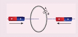
Predict the polarity of the capacitor in a closed circular loop when two bar magnets are moved as shown in the figure.
4.
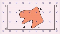
A flexible metallic loop abcd in the shape of a square is kept in a magnetic field with its plane perpendicular to the field. The magnetic field is directed into the paper normally. Find the direction of the induced current when the square loop is crushed into an irregular shape as shown in the figure.
5.
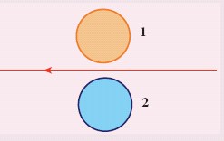
Using Lenz’s law, predict the direction of induced current in conducting rings 1 and 2 when current in the wire is steadily decreasing.
6.
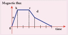
A graph between the magnitude of the magnetic flux linked with a closed loop and time is given in the figure. Arrange the regions of the graph in ascending order of the magnitude of induced emf in the loop.
7.
Calculate the instantaneous value at 60o, average value and RMS value of an alternating current whose peak value is 20 A.
8.
A coil of 200 turns carries a current of 4 A. If the magnetic flux through the coil is 6 × 10⁻⁵ Wb, find the magnetic energy stored in the medium surrounding the coil.
9.
Determine the self-inductance of 4000 turn air-core solenoid of length 2m and diameter 0.04 m.
10.
A bicycle wheel with metal spokes of 1 m long rotates in Earth’s magnetic field. The plane of the wheel is perpendicular to the horizontal component of Earth’s field of 4×10⁻⁵T. If the emf induced across the spokes is 31.4 mV, calculate the rate of revolution of the wheel.
11.
A fan of metal blades of length 0.4 m rotates normal to a magnetic field of 4 x 10 -3 T. If the induced emf between the centre and edge of the blade is 0.02 V, determine the rate of rotation of the blade.
12.
An induced current of 2.5 mA flows through a single conductor of resistance 100 Ω. Find out the rate at which the magnetic flux is cut by the conductor.
13.
A rectangular coil of area 6 cm2 having 3500 turns is kept in a uniform magnetic field of 0.4 T. Initially, the plane of the coil is perpendicular to the field and is then rotated through an angle of 180o . If the resistance of the coil is 35 Ω, find the amount of charge flowing through the coil.
14.
A closely wound circular coil of radius 0.02 m is placed perpendicular to the magnetic field. When the magnetic field is changed from 8000 T to 2000 T in 6 s, an emf of 44 V is induced in it. Calculate the number of turns in the coil. (Take π = \(\frac { 22 }{ 7 } \) )
15.
The magnetic flux passing through a coil perpendicular to its plane is a function of time and is given by\(\Phi\)B=(2t3+4t2+8t+8)Wb. If the resistance of the coil is 5 Ω, determine the induced current through the coil at a time t = 3 second.
16.
A straight metal wire crosses a magnetic field of flux 4 mWb in a time 0.4 s. Find the magnitude of the emf induced in the wire.
17.
A square coil of side 30 cm with 500 turns is kept in a uniform magnetic field of 0.4 T. The plane of the coil is inclined at an angle of 30o to the field. Calculate the magnetic flux through the coil.
18.
What are LC oscillations?
19.
Give any one definition of power factor.
20.
What is meant by wattles current?
21.
How will you define Q-factor?
22.
What do you mean by resonant frequency?
23.
Define electric resonance.
24.
What are phasors?
25.
How will you define RMS value of an alternating current?
26.
Define average value of an alternating current.
27.
List out the advantages of stationary armature-rotating field system of AC generator.
28.
Give the principle of AC generator.
29.
What is meant by mutual induction?
30.
What do you mean by self-induction?
31.
What for an inductor is used? Give some examples.
32.
Mention the ways of producing induced emf.
33.
How is Eddy current produced? How do they flow in a conductor?
34.
State Fleming’s right hand rule.
35.
36.
State Faraday’s laws of electromagnetic induction.
37.
What is meant by electromagnetic induction?
38.
A capacitor of capacitance \(\\ \frac { { 10 }^{ 2 } }{ \pi } \mu F\\ \) is connected across a 220 V, 50 Hz A.C. mains. Calculate the capacitive reactance, RMS value of current and write down the equations of voltage and current.
39.
A 400 mH coil of negligible resistance is connected to an AC circuit in which an effective current of 6 mA is flowing. Find out the voltage across the coil if the frequency is 1000 Hz.
40.
The current flowing in the first coil changes from 2 A to 10 A in 0.4 s. Find the mutual inductance between two coils if an emf of 60 mV is induced in the second coil. Also determine the magnitude of induced emf in the second coil if the current in the first coil is changed from 4 A to 16 A in 0.03 s. Consider only the magnitude of induced emf.
41.
The self-inductance of an air-core solenoid is 4.8 mH. If its core is replaced by iron core, then its self-inductance becomes 1.8 H. Find out the relative permeability of iron.
42.
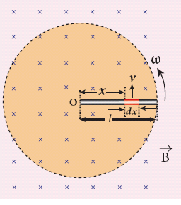
A copper rod of length l rotates about one of its ends with an angular velocity ω in a magnetic field B as shown in the figure. The plane of rotation is perpendicular to the field. Find the emf induced between the two ends of the rod.
43.
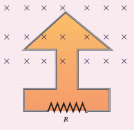
The magnetic flux passes perpendicular to the plane of the circuit and is directed into the paper. If the magnetic flux varies with respect to time as per the following relation \(\Phi_B\) = (2t3 + 3t2 + 8t + 5)mWb, what is the magnitude of the induced emf in the loop when t = 3 s? Find out the direction of current through the circuit.
44.
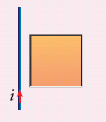
If the current i flowing in the straight conducting wire as shown in the figure decreases, find out the direction of induced current in the metallic square loop placed near it.
45.
A straight conducting wire is dropped horizontally from a certain height with its length along east-west direction. Will an emf be induced in it? Justify your answer.
46.
A closed coil of 40 turns and of area 200 cm2, is rotated in a magnetic field of flux density 2 Wb m–2. It rotates from a position where its plane makes an angle of 30o with the field to a position perpendicular to the field in a time 0.2 s. Find the magnitude of the emf induced in the coil due to its rotation.
47.
A cylindrical bar magnet is kept along the axis of a circular solenoid. If the magnet is rotated about its axis, find out whether an electric current is induced in the coil.
48.
A circular antenna of area 3 m2 is installed at a place in Madurai. The plane of the area of antenna is inclined at 47o with the direction of Earth’s magnetic field. If the magnitude of Earth’s field at that place is 4.1 x 10⁻⁵ T find the magnetic flux linked with the antenna.
1.
Power factor will be maximum, when Φ = 0 i.e., \(\tan ^{-1}\left(\frac{X_L-X_C}{R}\right)=0\)
\(\therefore X_L=X_C \Rightarrow L \omega=\frac{1}{C \omega} \)
\(\therefore \omega=\frac{1}{2 \pi \sqrt{L C}}\)
∴ Current I be max \(I_m=\frac{V_m}{R}\)
Hence power factor of a RLC series circuit becomes maximum, when
(i) \(X_L=X_C\)
(ii) Current \(I_m=\frac{V_m}{R}\) will be maximum
(iii) Frequency \(\omega_r=\frac{1}{2 \pi \sqrt{L C}}\)
2.
In the inductor voltage leads current by 90°
.JPG)
In the capacitor current leads voltage by 90°
.JPG)
Hence in series LC circuit, the voltage across L and C are 180° out of phase
.JPG)
3.
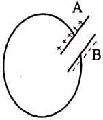
The plate A is positively charged
The plate B is negatively charged.
4.
The direction of induced current is, a → b, b → c, c → d and d → a
5.
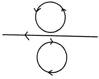
(i) Current is induced in the anticlockwise direction in the upper coil. Then only as per Lenz's law, the induced current will oppose the motion of the magnet.
(ii) In the lower coil, current is induced in the clockwise direction. As per Lenz's law the direction of induced emf will in opposite direction of motion of the magnet.
6.
Magnitude of induced \(\mathrm{emf}|\mathrm{e}|=\left|-\frac{d \phi}{d t}\right|\)
\(\therefore c=\frac{d \phi}{d t}\)
(i) In the region ab,
\(c_1=\frac{d \phi_1}{d t}=\frac{4-0}{1-0}=\frac{4}{1}=4 \mathrm{~V}\)
(ii) In the region bc,
\(c_2=\frac{d \phi_2}{d t}=\frac{4-4}{3-1}=\frac{0}{2}=0 \mathrm{~V}\)
(iii) In the region cd,
\(e_3=\frac{d \phi_2}{d t}=\frac{4-2}{4-3}=\frac{2}{1}=2 \mathrm{~V}\)
(iv) In the region de,
Hence,
\(e_4=\frac{d \phi_4}{d t}=\frac{2-0}{7-4}=\frac{2}{3}=0.66 V \)
\(\mathrm{e}_2<\mathrm{e}_4<\mathrm{e}_3<\mathrm{e}_1\)
In the ascending order of the magnitude of induced emf
Region bc < Region de < Region cd < Region ab.
7.
Angle, \( \theta=60^{\circ}\)
Peak value of current, \(I_{P_m}=20 \mathrm{~A}\)
(i) Instantaneous value of current at 60o,
\(i =I_m \sin \theta \)
\(=20 \times \sin 60^{\circ}=\frac{20 \times \sqrt{3}}{2} \)
\(=10 \times 1.732 \)
\(i =17.32 \mathrm{~A}\)
(ii) Average value of current,
\(I_{\mathrm{av}}=0.637 I_m \)
\(I_{\mathrm{av}}=0.637 \times 20 \)
\(I_{\mathrm{av}}=12.74 \mathrm{~A}\)
(iii) RMS value of current,
\(I_{\mathrm{rms}}=0.707 I_m=0.707 \times 20 \)
\(I_{\mathrm{rms}}=14.14 \mathrm{~A}\)
8.
Current, I = 4 A, Magnetic flux, \(\phi=6 \times 10^{-5} \mathrm{~Wb}\), Number of turns, N = 200
Self inductance, \(L=\frac{N \phi}{I}\)
\(\therefore L =\frac{200 \times 6 \times 10^{-5}}{4} \)
\(L =300 \times 10^{-5} \mathrm{H}=3 \times 10^{-3} \mathrm{H}\)
∴ Magnetic energy, \(U_s=\frac{1}{2} L I^2\)
\(U_s =\frac{1}{2} \times 3 \times 10^{-3} \times(4)^2 \)
\(=\frac{1}{2} \times 3 \times 10^{-3} \times 16 \)
\(=24 \times 10^{-3} \mathrm{~J}=0.024 \mathrm{~J}\)
Magnetic energy = 0.024 J
9.
Relative permeability of air-core solenoid is μr = 1
Length of the solenoid, I = 2 m, Number of turns, N = 4000
Diameter of the solenoid, d = 4 x 10⁻²m
Area of solenoid, A = \(\frac{\pi d^2}{4}\)
\(A =\frac{3.14 \times\left(4 \times 10^{-2}\right)^2}{4} \)
\(=12.56 \times 10^{-4} \mathrm{~m}^2\)
Self inductance of a solenoid is, \(L=\frac{\mu_0 \mu_r N^2 A}{l}\)
\(\therefore L =\frac{4 \pi \times 10^{-7} \times 1 \times(4000)^2 \times 12.56 \times 10^{-4}}{2} \)
\(=2 \times 3.14 \times 10^{-7} \times 16 \times 10^6 \times 12.56 \times 10^{-4} \)
\(=1262 \times 10^{-5} \mathrm{H}=12.62 \times 10^{-3} \mathrm{H} \)
\(\therefore L =12.62 \mathrm{mH}\)
∴ Self inductance of a solenoid L =12.62 mH
10.
Horizontal component of Earth's magnetic field, \(B_H=4 \times 10^{-5} \mathrm{~T}\)
Length of a spoke, l = 1 m,
Induced emf, \(e = 31.4 \times 10^{-3} \mathrm{~V}\)
Change in magnetic flux, \(d \phi=B d s\)
\(\therefore d \phi=B \times \pi l^2\)
we know that, \(d t=\frac{2 \pi}{\omega}\)
\(\therefore \text {Magnitude of induced emf, } e =\left|-\frac{d \phi}{d t}\right| \)
\(e =\frac{d \phi}{d t}=\frac{B \pi l^2}{2 \pi / \omega}=\frac{1}{2} B l^2 \omega \)
\(e =\frac{1}{2} B l^2 \times 2 \pi v=\pi B l^2 v \quad(\because \omega=2 \pi v)\)
∴ Rate of revolution, \(v=\frac{e}{\pi B l^2}\)
\(v =\frac{31.4 \times 10^{-3}}{3.14 \times 4 \times 10^{-5} \times(1)^2} \)
\(=\frac{10 \times 10^{-3+5}}{4}=\frac{10^3}{4}=250 \mathrm{rps}\)
∴ Rate of rotation of the wheel v = 250 revolutions/second.
11.
Magnetic field B = 4 x 10⁻³ T
Induced emf, e = 0.02V = 2 x 10⁻² V
Length of a blade, I= 0,4; m = 4 x 10⁻¹ m
Change in magnetic flux, dΦ = Bds
∴ dΦ = B x πl2
we know that, dt = \(\frac{2\pi}{\omega}\)
∴ Magnitude of induced emf, e \(=|-\frac{dΦ}{dt}|\)
\(e=\frac{dΦ}{dt}=\frac{B\pi l^2}{ 2\pi l \omega} =\frac{1}{ 2}Bl^2\omega\)
\(=\frac{1}{ 2}Bl^2 \times 2\pi v= \pi Bl^2v \quad (\because \omega=2\pi v)\)
Rate of rotation of the blade, \(v=\frac{e}{\pi Bl^2}\)
\(v=\frac { 2.10^{-2} }{ 3.14\times 4\times 10^{ -3 }\times(4 \times10^{-1})^2 } \)
\(=\frac { 2 \times10^{-2} }{ 3.14 \times64\times10^{-5} } =\frac{2\times10^{-2+5}}{200.96}\)
v = 0.00995 x 10³
v = 9.95 rev/s
Rate of rotation of the blade = 9.95 revolutions /second
12.
Resistance of a conductor R = 100 Ω
Induced current, i = 2.5 x 10⁻³ A
Induced emf, e = iR
e = 2.5 x 10-3 x 100
e = 250 x 10-3 V
But, \(e=-\frac { d\Phi }{ dt } =|-\frac { d\Phi }{ dt } |=\frac { d\Phi }{ dt } \)
∴ Rate of change of flux is \(\frac { d\Phi }{ dt } =e\)
250 x 10-3 wb/s = 250mWb/s
∴ Rate of change of flus = 250 m Wb/s
13.
Area of a rectangular coil, \(A=6 \times 10^{-4} \mathrm{~m}^2, Resistance \ \mathrm{R}=35 \Omega\)
Number of turns of the coil, N = 3500 turns
Magnetic field, B = 0.4 T
Angle of orientation, \(\theta=\pi-\frac{\pi}{2}=\frac{\pi}{2} \mathrm{rad}=90^{\circ}\)
Induced emf, e=N A B sin θ
\(e=3500 \times 6 \times 10^{-4} \times 0.4 \times \sin 90^{\circ}\)
\(=3500 \times 2.4 \times 10^{-4} \times 1 \)
\(=840 \times 10^{-3} \mathrm{V} \)
\(I=\frac{e}{R}=\frac{1440 \times 10^{-1}}{35} \)
\(I=24 \times 10^{-3} A\)
Charge, Q = It
\(=24 \times 10^{-3} \times 2 \)
\(=48 \times 10^{-3} \mathrm{C} \)
\(\therefore Charge Q=48 \times 10^{-3} \mathrm{C}\)
14.
Change in magnetic field, dB = (8000 - 2000) = 6000 Wb
Change in time, dt = 6s
Radius of the coil, r = 2 x 10⁻² m
Induced emf, e = 44 V,
Area of the coil A =πr2 = \(\frac { 22 }{ 7 } \) x (2 x 10⁻²)2
= 12.56 x 10⁻⁴ m2
∴ Number of turns in the coil,
\(N=\frac { e }{ A\frac {dB}{dt }} \frac{44}{12.56\times10^{-4} \times(6000/6)}\)
\(N=\frac { 44 \times10 }{12.56 }=3.503\times10=35 \)
∴ Number of turns in the coil = 35
15.
Induced emf, e = \(\frac { d\Phi _{ B } }{ dt } \)
=\(\frac {- d }{ dt } \) (2t3 + 4t2 + 8t + 8) = -(6t2 + 8t + 8)
When t= 3 s
e = -(6(3)2 + 8(3) + 8) = -(54 + 24 + 8) = -86
Magnitude of emf, e =|-86| = 86 V
Resistance of the coil, R = 5Ω
∴ Induced curent, I =\(\frac { e }{ R } \)
I=\(\frac { 86 }{ 5 } \) = 17.2 A
∴ Induced current through the coil = 17.2 A
16.
Change in magnetic flux, dф = 4 x 10⁻³ Wb
Change in time, dt = 0.4 s
Magnitude of Induced emf \(= |\frac { -d\Phi }{ dt }|=\frac { d\Phi }{ dt }\)
\(=\frac { 4\times 10^{ -3 } }{ 0.4 } \) = 10 x 10-3 V = 10 mv
∴ Magnitude of induced emf =10 mV
17.
Number of turns, N = 500
Area of cross section, A = 30 x 30 x 10-4
= 900 x 10-4 m2
Magnetic field, B = 0.4 T
Angle of inclination θ = 900 - 300= 600
∴ Magnetic flux Φ = NAB cos θ
∴ Φ = 500 x 900 x 10-4 x 0.4 x cos600
= 45 x 104 x 10-4 x 4 x 10-1 x \(\frac{1}{2}\)
Φ= 9 x 10-1 = 9.0 Wb
∴ Magnetic flux Φ = 9.0 Wb
18.
Whenever energy is given to a circuit containing a pure indicator L and a capacitor of capacitance C, the energy oscillates back and fourth between the magnetic field of the indicator and the electric field of the capacitor. Thus the electrical oscillations of definite frequency are generated. these oscillations are called LC oscillations.
19.
Power factor is defined as the ratio of resistance to the impedance of an AC circuit
Power factor \(\cos \phi=\frac{R}{2}\)
\(=\frac{Resistance}{Impedance}\)
20.
The current in an AC circuit is said to be wattless current if the power consumed by it is zero.
21.
Q factor is defined as the ratio of voltage across L or C to resonance to the applied voltage
Q - factor = \(\frac{Voltage \ across \ L \ or \ C \ resonance }{Applied \ voltage}\)
\(Q-factor=\frac{X_{L}}{R}=\frac{1}{R}\sqrt\frac{{L}}{C}\)
22.
Resonant frequency is the frequency of the applied alternating source at which the current in the circuit reaches its maximum value.
23.
When the frequency of the applied alternating source (ωr) is equal to the natural frequency \(\left[\frac{1}{\sqrt{L C}}\right]\) of the RLC circuit, the current in the circuit reaches its maximum value. Then, the circuit is said to be in electrical resonance.
24.
A sinusoidal alternating voltage (or current) can be represented by a vector which rotates about the origin in anti-clockwise; direction at a constant angular velocity ω. Such a rotating vector is called a phasor.
25.
RMS value is also defined as that value of the steady current which when flowing through a given circuit for a given time produces the same amount of heat as produced by the alternating current when flowing through the same Circuit for the same time. (or)
The root mean square value of an alternating current is defined as the square root of the mean of the squares of all currents over one cycle
\(I_{RMS}=\sqrt\frac{\text {Area of one cycle of squared wave}}{\text {Base length of one cycle}}\)
26.
The average value of alternating current is defined as the average of all values of current over a positive half-cycle or negative half-cycle.
27.
(i) The current is drawn directly from fixed terminals on the stator without the use of brush contacts.
(ii) The insulation of stationary armature winding is easier.
(iii) The number of sliding contacts (slip rings) is reduced. Moreover, the sliding contacts are used for low-voltage DC Source.
(iv) Armature windings can be constructed more rigidly to prevent deformation due to any mechanical stress.
28.
AC generator work on the principle of electromagnetic induction. The relative motion between a conductor and a magnetic field changes the magnetic flux linked with the conductor which in turn, induces an emf
29.
When an electric current passing through a coil changes with time, an emf is induced in the neighboring coil. This phenomenon is known as mutual induction.
30.
An electric current flowing through a coil will set up a magnetic field around it. Therefore the magnetic flux of the magnetic field is linked with that coil it self. If this flux is changed by changing the current, an emf is induced in that same coil. This phenomenon is known as self-induction.
31.
Inductor is a device used to store energy in a magnetic field, when an electric current flows through it. Examples: coils, solenoids and toroids
32.
Emf can be produced by changing magnetic flux in any of the following ways:
(i) By changing the magnetic field B
(ii) By changing the area A of the coil and
(iii) By changing the relative orientation θ of the coil with magnetic field.
33.
Even for a conductor in the form of a sheet or plate, an emf is induced when magnetic flux linked with it changes. But the difference is that there is no definite loop or path for induced current to flow away. As a result, the induced currents flow in concentric circular paths. As these electric currents resemble eddies of water, these are known as Eddy currents. They are also called Foucault currents.
34.
The thumb, index finger and middle finger of right hand are stretched out in mutually perpendicular directions. If the index finger points the direction of the magnetic field and the thumb indicates the direction of motion of the conductor, then the middle finger will indicate the direction of the induced current.
35.
36.
First law:
Whenever magnetic flux linked with a closed circuit changes, an emf is induced in the circuit. Which lasts in the circuit as long as the magnetic flux is changing.
Second law:
The magnitude of induced emf in a closed circuit is equal to the time rate of change of magnetic flux linked with the circuit.
37.
Whenever the magnetic flux linked with a closed coil changes, an emf is induced and hence an electric current flows in the circuit. This current is called an induced current and the emf giving rise to such current is called an induced emf. This phenomenon is known as electromagnetic induction.
38.
\(C=\frac { { 10 }^{ 2 } }{ \pi } \times { 10 }^{ -6 }F,{ V }_{ RMS }=220V;f=50Hz\)
(i) Capacitive reactance,
\({ X }_{ c }=\frac { 1 }{ \omega C } =\frac { 1 }{ 2\pi fC } \)
\(=\frac { 1 }{ 2\times \pi \times 50\times \frac { { 10 }^{ -4 } }{ \pi } } =100\Omega \)
(ii) RMS value of current,
\(\\ { I }_{ RMS }=\frac { { V }_{ RMS } }{ { X }_{ c } } =\frac { 220 }{ 100 } =2.2\ A\)
(iii) Vm = 220 x \(\sqrt{2}\) = 311V
Im = 2.2 x \(\sqrt{2}\) = 3.1A
Therefore,
v = 311sin314t
i = 3.1sin\((314t+\frac { \pi }{ 2 } )\)
39.
L = 400 x 10-3 H; Ieff = 6 x 10⁻³A
f = 1000 Hz
Inductive reactance, XL= L\(\omega\) = L x 2\(\pi\)f
= 2 x 3.14 x 1000 x 0.4
= 2512 Ω
Voltage across L,
V = I X L = 6 x 10-3 x 2512
V = 15.072 V (RMS)
40.
Case (i):
di1 = 10 – 2 = 8 A; dt = 0.4 s;
ε2 = 60 x 10-3V
Case(ii):
di1 = 16 – 4 = 12 A; dt = 0.03 s
(i) Mutual inductance between the coils.
\({ M }=\frac { { \epsilon }_{ 2 } }{ \frac { { di }_{ 1 } }{ dt } } \)
\(=\frac { 60\times { 10 }^{ -3 }\times 0.4 }{ 8 } \)
\({ M }=3\times { 10 }^{ -3 }H\)
(ii) Induced emf in the second coil due to the rate of change of current in the first coil is
\({ \epsilon }_{ 2 }={ M }=\frac { { di }_{ 1 } }{ dt } \)
\(=\frac { 3\times { 10 }^{ -3 }\times 12 }{ 0.03 } \)
ε2 = 1.2V
41.
Lair = 4.8 x 10⁻³H
Liron = 1.8H
Lair = \(\mu_{o}\)n2Al = 4.8 x 10⁻³H
Liron = \(\mu_{o}\)n2Al = \(\mu_{o}\mu_r\)n2Al = 1.8H
\(\therefore { \mu }_{ r }=\frac { { L }_{ iron } }{ { L }_{ air } } =\frac { 1.8 }{ 4.8\times { 10 }^{ -3 } } =375\)
42.
Consider a small element of length dx at a distance x from the centre of the circle described by the rod. As this element moves perpendicular to the field with a linear velocity v = xω, the emf developed in the element dx is dε = Bvdx = B(xω)dx
This rod is made up of many such elements, moving perpendicular to the field. The emf developed across two ends is
\(\epsilon =\int { d\epsilon } =\int _{ 0 }^{ l }{ B\omega xdx } =B\omega { { \left[ \frac { { x }^{ 2 } }{ 2 } \right] } }_{ 0 }^{ l }\)
\(\epsilon =\frac { 1 }{ 2 } B\omega { l }^{ 2 }\)
43.
\(\Phi_B\) = (2t3 + 3t2 + 8t + 5)mWb; N = 1;t = 3 s
i) \(ε=\frac { d(N{ \Phi }_{ B }) }{ dt } \)
\(=\frac { d }{ t } \left( { 2t }^{ 3 }+{ 3t }^{ 2 }+8t+5 \right) \times { 10 }^{ -3 }\)
= (6t2 + 6t + 8) x 10-3 V
At t = 3 s,
ε = [( 6 x 9) + (6 x 3) + 8] x 10-3
= 80 x 10-3V = 80mV
(ii) As time passes, the magnetic flux linked with the loop increases. According to Lenz’s law, the direction of the induced current should be in a way so as to oppose the flux increase. So, the induced current flows in such a way to produce a magnetic field opposite to the given field. This magnetic field is perpendicularly outwards. Therefore, the induced current flows in anticlockwise direction.
44.
From right hand rule, the magnetic field by the straight wire is directed into the plane of the square loop perpendicularly and its magnetic flux is decreasing. The decrease in flux is opposed by the current induced in the loop by producing a magnetic field in the same direction as the magnetic field of the wire. Again from right hand rule, for this inward magnetic field, the direction of the induced current in the loop is clockwise.
45.
Yes! An emf will be induced in the wire because it moves perpendicular to the horizontal component of Earth’s magnetic field and hence it cuts the magnetic lines of Earth's magnetic field.
46.
N = 40 turns; B = 2 Wb m-2
A = 200 cm2 = 200 x 10-4 m2;
Initial flux, \(\Phi_i\) = BA cos\(\theta\)
= 2 x 200 x 10-4 x cos60o
since θ = 90°− 30°= 60°
\(\Phi_i\)= 2 x 10⁻² Wb
Final flux, \(\Phi_f\) = BA cos\(\theta\)
= 2 x 200 x 10-4 x cos0o since \(\theta\) = 0o
\(\Phi_f\) = 4 x 10⁻²Wb
Magnitude of the induced emf is
\(ε =N\frac { d{ \Phi }_{ B } }{ dt } \)
\(=\frac { 40\times (4\times { 10 }^{ -2 }-2\times { 10 }^{ -2 }) }{ 0.2 } =4V\)
47.
The magnetic field of a cylindrical magnet is symmetrical about its axis. As the magnet is rotated along the axis of the solenoid, there is no induced current in the solenoid because the flux linked with the solenoid does not change due to the rotation of the magnet.
48.
B = 4.1 x 10⁻⁵ T; θ = 90o – 47o = 43° ;
A = 3m2
We know that \(\Phi_{B}=B A \cos \theta\)
\(\Phi_{\mathrm{B}}\) = 4.1 x 10–5 x 3 x cos 43o
= 4.1 x 10–5 x 3 x 0.7314
= 89.96 \(\mu \mathrm{Wb}\).

12th Standard Syllabus & Materials
12th Standard
TN 12th Computer Applications களப்பெயர் முறைமை (DNS) Sample Question Papers Study Material - QB365 Set A
NEW12th Standard
TN 12th Computer Applications வலையமைப்பு எடுத்துக்காட்டுகள் மற்றும் நெறிமுறைகள் Sample Question Papers Study Material - QB365 Set A
NEW12th Standard
TN 12th Computer Applications கணினி வலையமைப்பு ஓர் அறிமுகம் Sample Question Papers Study Material - QB365 Set A
NEW12th Standard
TN 12th Computer Applications PHP-உடன் MySQL-ஐ இணைத்தல் Sample Question Papers Study Material - QB365 Set A



Tamilnadu Stateboard 12th Standard Subjects

Maths

Chemistry
Physics

Biology

Computer Science

Business Maths and Statistics

Economics

Commerce

Accountancy

History

Computer Applications
Biology
Computer Technology
Computer Applications
Computer Science
Business Maths and Statistics
Commerce
Economics
Maths
Chemistry
Physics
Computer Technology
History
Accountancy

Tamil

English

French
Tamilnadu Stateboard Standards

