
 100% FREE ACCESS
12th Standard Syllabus & Materials
12th Standard
TN 12th Maths Applications of Matrices and Determinants Sample Question Papers Study Material - QB365 Set A
NEW12th Standard
TN 12th Computer Applications மின்னணு தரவு பரிமாற்றம் Sample Question Papers Study Material - QB365 Set A
NEW12th Standard
TN 12th Computer Applications மின் - வணிக பாதுகாப்பு அமைப்புகள் Sample Question Papers Study Material - QB365 Set A
NEW12th Standard
TN 12th Computer Applications மின்னணு செலுத்தல் முறைகள் Sample Question Papers Study Material - QB365 Set A
NEW12th Standard
TN 12th Computer Applications மின் - வணிகம் Sample Question Papers Study Material - QB365 Set A
NEW12th Standard
TN 12th Computer Applications திறந்த மூல கருத்துருக்கள் Sample Question Papers Study Material - QB365 Set A

Published on: 02/09/2022
QB365 provides a detailed and simple solution for every Possible Creative Questions in Class 12 Physics Subject - Retirement and Death of a Partner, English Medium. It will help Students to get more practice questions, Students can Practice these question papers in addition to score best marks.
Download Tamil Nadu 12th Standard Physics question papers, model tests, one-mark questions, important questions, and public exam papers in PDF format. Free study materials and answer keys for TN State Board students.
Questions + Answers key
Take MCQ Physics Test1.
Define power factor?
2.
What is the value of power if the circuit is
(i) purely resistive
(ii) Purely inductive or capacitive?
3.
What is the signifienance of Quality factor or Q-factor.
4.
When does the phenomenon of resonance is possibble in the circuit?
5.
Write the application of series RLC resonant circut
6.
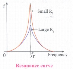
Draw a graph showing variation of current with changing frequency of applied voltage in a series LCR circuit for two different values of resistance R1 & R2 (I1 > I2) fr - resonant frequency.
7.
What is resonant frequency?
8.
Distinguish between AC and DC.
9.
What is inductive reactance X1? How does it depend on the frequency and give its unit?
10.
What is meant by Sinusoidal alternating voltage and current? Give its expression.
11.
What is meant by AC vollage?
12.
Explain the use of transformers in long distance transmission of electric power.
13.
What is meant by power transmission?
14.
Define Magnetic Flux.
15.
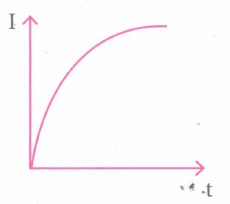
Draw graphs showing the distribution of charge in a capacitor and current through an inductor during LC oscillations with respect to time. Assume that the charge in the capacitor is maximum initially.
1.
The power factor of a circuit is defined in one of the following ways:
(i) Power factor = cos Φ= cosine of the angle of lead or leg
(ii) Power factor = \(\frac{R}{Z}\) = \(\frac{Resistance}{Impedance}\)
(iii) Power factor = \(\frac { VI \ cos \ \Phi }{ VI } \) = \(\frac{True \ power}{Apparent \ power}\)
2.
(i) For a purely resistive circuit, the phase angle between voltage and current is zero and cos Φ = 1
ஃ Pav = VRMSIRMS
(ii) For a purely inductive or capacitive circuit, the phase angle is ±\(\frac { \pi }{ 2 } \) and cos \(\left( \pm \frac { \pi }{ 2 } \right) \)
3.
The current in the series RLC circuit becomes maximum at resonance. Due to the increase in current, the voltage across L and C are also increased. This magnification of voltages at series resonance is termed as Q-factor. It gives a measure of sharpness of current peak in the resanance condition of LCT circuit
4.
The phenomenon of electrical resonance is possible when the circuit contains both L and C. Only then does the voltage across L and C cancels one another when VL and VC are 1800 out of phase and the circuit becomes purely resistive. This implies that resonance will not occur in RL and RC circuits.
5.
RLC circuits have many applications like filter circuits, oscillators, voltage multipliers, etc. An important use of series RLC resonant circuits is in the tuning circuits of radio and TV systems.
6.
The maximum current at series resonance is limited by the resistance of the circuit. For smaller resistance, a larger current with a sharper curve is obtained and vice versa.
7.
When the frequency of the applied alternating source (ωr) is equal to the natural frequency \(\left[ \frac { 1 }{ \sqrt { LC } } \right] \) of the RLC circuit, the current in the circuit reaches its maximum value. Then the circuit is said to be in electrical resonance. The frequency at which resonance takes place is called resonant frequency.
Resonant angular frequency, ωr = \(\frac { 1 }{ \sqrt { LC } } \)
8.
|
AC |
DC |
|---|---|
| It is the current varying to the magnitude continuously and reverses the direction periodically. | The current and voltage in a DC system remain constant over a period of time and flows in the same fixed direction. |
| I = Im sin ωt | i = \(\frac{Q}{t}\) |
| The average value of AC over the complete cycle is zero. | The current is steady with respect to time. |
9.
The resistance offered by the inductor, called inductive reactance (XL). It is measured in ohm.
XL = ωL
XL = 2πfL
where f is the frequency of the alternating current. For a steady current, f = 0. Therefore, XL = 0. Thus an ideal inductor offers no resistance to steady DC current.
10.
If the waveform of alternating voltage is a sine wave, then it is known as sinusoidal alternating voltage which is given by the relation.
v = Vm sin ωt
where v is the instantaneous value of alternating voltage; Vm is the maximum value (amplitude) and w is the angular frequency of the alternating voltage.
i = Im sin ωt
where Im is the maximum value (amplitude) of the alternating current. The direction of sinusoidal voltage or current is reversed after every half-cycle and its magnitude is also changing continuously.
11.
An alternating voltage is the voltage which changes polarity at regular intervals of time and the direction of the resulting alternating current also changes accordingly.
12.
At the transmitting point, the voltage is increased and the corresponding current is decreased by using a step-up transformer. Then it is transmitted through transmission lines. This reduced current at high voltage reaches the destination without any appreciable loss. At the receiving point, the voltage is decreased and the current is increased to appropriate values by using a step-down transformer, and then it is given to consumers.
13.
Most of the power stations are located in remote places. Hence the electric power generated is transmitted over long distances through transmission lines to reach towns or cities where it is actually consumed. This process is called power transmission.
14.
The magnetic flux through an area A in a magnetic field is defined as the number of magnetic field lines passing through that area normally and is given by the equation.
\({ \Phi }_{ B }=\int _{ A }^{ }{ \vec { B } .d\vec { A } =BAcos\theta } \)
where the integral is taken over the area A and θ is the angle between the direction of the magnetic field and the outward normal to the area.
15.
For capacitor:
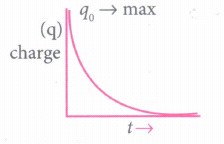
The charge decays exponentially with time. When the capacitor discharge.
For Inductor:

12th Standard Syllabus & Materials
12th Standard
TN 12th Computer Applications வலையமைப்பு வடமிடல் Sample Question Papers Study Material - QB365 Set A
NEW12th Standard
TN 12th Computer Applications களப்பெயர் முறைமை (DNS) Sample Question Papers Study Material - QB365 Set A
NEW12th Standard
TN 12th Computer Applications வலையமைப்பு எடுத்துக்காட்டுகள் மற்றும் நெறிமுறைகள் Sample Question Papers Study Material - QB365 Set A
NEW12th Standard
TN 12th Computer Applications கணினி வலையமைப்பு ஓர் அறிமுகம் Sample Question Papers Study Material - QB365 Set A



Tamilnadu Stateboard 12th Standard Subjects

Maths

Chemistry
Physics

Biology

Computer Science

Business Maths and Statistics

Economics

Commerce

Accountancy

History

Computer Applications
Biology
Computer Technology
Computer Applications
Computer Science
Business Maths and Statistics
Commerce
Economics
Maths
Chemistry
Physics
Computer Technology
History
Accountancy

Tamil

English

French
Tamilnadu Stateboard Standards

