
 100% FREE ACCESS
12th Standard Syllabus & Materials
12th Standard
TN 12th Maths Applications of Matrices and Determinants Sample Question Papers Study Material - QB365 Set A
NEW12th Standard
TN 12th Computer Applications மின்னணு தரவு பரிமாற்றம் Sample Question Papers Study Material - QB365 Set A
NEW12th Standard
TN 12th Computer Applications மின் - வணிக பாதுகாப்பு அமைப்புகள் Sample Question Papers Study Material - QB365 Set A
NEW12th Standard
TN 12th Computer Applications மின்னணு செலுத்தல் முறைகள் Sample Question Papers Study Material - QB365 Set A
NEW12th Standard
TN 12th Computer Applications மின் - வணிகம் Sample Question Papers Study Material - QB365 Set A
NEW12th Standard
TN 12th Computer Applications திறந்த மூல கருத்துருக்கள் Sample Question Papers Study Material - QB365 Set A

Published on: 02/09/2022
QB365 provides a detailed and simple solution for every Possible Book Back Questions in Class 12 Physics Subject - Retirement and Death of a Partner, English Medium. It will help Students to get more practice questions, Students can Practice these question papers in addition to score best marks.
Download Tamil Nadu 12th Standard Physics question papers, model tests, one-mark questions, important questions, and public exam papers in PDF format. Free study materials and answer keys for TN State Board students.
Questions + Answers key
Take MCQ Physics Test1.
Explain the generation of LC oscillations in a circuit containing an inductor of inductance L and a capacitor of capacitance C.
2.
Prove that the total energy is conserved during LC oscillations.
3.
Obtain an expression for average power of AC over a cycle. Discuss its special cases.
4.
Define inductive and capacitive reactance. Give their units.
5.
Derive an expression for phase angle between the applied voltage and current in a series RLC circuit.
6.
Find out the phase relationship between voltage and current in a pure inductive circuit.
7.
Give the advantage of AC in long distance power transmission with an illustration.
8.
Explain the construction and working of transformer.
9.
How are the three different emfs generated in a three-phase AC generator? Show the graphical representation of these three emfs.
10.
Explain the working of a single-phase AC generator with necessary diagram.
11.
Elaborate the standard construction details of AC generator.
12.
Show mathematically that the rotation of a coil in a magnetic field over one rotation induces an alternating emf of one cycle. (or) Emf induced by changing relative orientation of the coil with the magnetic field.
13.
Show that the mutual inductance between a pair of coils is same (M12 = M21). (or) Derive the equation for inductance of a solenoid. Assume that the length of the solenoid is greater than its diameter.
14.
How will you define the unit of inductance?
15.
Define self-inductance of a coil interms of
(i) magnetic flux and
(ii) induced emf.
16.
Give the uses of Foucault current.
17.
Show that Lenz’s law is in accordance with the law of conservation of energy.
18.
Give an illustration of determining direction of induced current by using Lenz’s law.
19.
Establish the fact that the relative motion between the coil and the magnet induces an emf in the coil of a closed circuit.
20.
Compare the electromagnetic oscillations of LC circuit with the mechanical oscillations of blockspring system qualitatively to find the expression for angular frequency of LC oscillator.
21.
Mention the various energy losses in a transformer.
22.
23.
An inductor of inductance L carries an electric current i. How much energy is stored while establishing the current in it?
24.
Assuming that the length of the solenoid is large when compared to its diameter, find the equation for its inductance.
25.
What do you understand by self - inductance of a coil? Give its physical significance.
1.
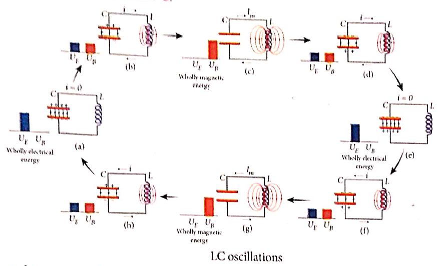
Generation of LC oscillations:
(i) Let us assume that the capacitor is fully charged with maximum charge Qm at the initial stage. So that the energy stored in the capacitor is maximum and is given by \(\mathrm{U}_{\mathrm{E}}=\frac{Q_{m}^{2}}{2 C}\) . As there is no current in the inductor, the energy stored in it is zero i.e., UB = 0. Therefore, the total energy is wholly electrical.
(ii) The capacitor now begins to discharge through the inductor that establishes current i in clockwise direction. This current produces a magnetic field around the inductor and the energy stored in the inductor is given by, \(\mathrm{U}_{\mathrm{B}}=\frac{Li^{2}}{2 }\). As the charge in the capacitor decreases, the energy stored in it also decreases and is given by, \(\mathrm{U}_{\mathrm{r}}=\frac{q^{2}}{2C }\). Thus there is a transfer of some part of energy from the capacitor to the inductor. At that instant, the total energy is the sum of electrical and magnetic energies.
(iii) When the charges in the capacitor are exhausted, its energy becomes zero i.e.,UE = 0. The energy is fully transferred to the magnetic field of the inductor and its energy is maximum. This maximum energy is given by \(\mathrm{U}_{\mathrm{B}}=\frac{Li^{2}_m}{2 }\) where, lm the is maximum current flowing in the circuit. The total energy is wholly magnetic
(iv) Even though the charge in the capacitor is zero, the current will continue to flow in the same direction because the inductor will not allow it to stop immediately. The current is made to flow with decreasing magnitude by the collapsing magnetic field of the inductor.
(v) As a result of this, the capacitor begins to charge in the opposite direction. A part of the energy is transferred from the inductor back to the capacitor. The total energy is the sum of the electrical and magnetic energies.
(vi) When the current in the circuit reduces to zero, the capacitor becomes fully charged in the opposite direction. The energy stored in the capacitor becomes maximum. Since the current is zero, the energy stored in the inductor is zero. The total energy is wholly electrical.
(vii) The state of the circuit is similar to the initial state but the difference is that the capacitor is charged in opposite direction. The capacitor then starts to discharge through the inductor with anti-clockwise current. The total energy is the sum of the electrical and magnetic energies.
(viii) As already explained, the processes are repeated in opposite direction. Finally, the circuit returns to the initial state. Thus, when the circuit goes through these stages, an alternating current flows in the circuit. As this process is repeated again and again, the electrical oscillations of definite frequency are generated. These are known as LC oscillations.
(ix) In the ideal LC circuit, there is no loss of energy. Therefore, the oscillations will continue indefinitely. Such oscillations are called undamped oscillations.
2.
During LC oscillations in LC circuits, the energy of the system oscillates between the electric field of the capacitor and the magnetic field of the inductor. Although, these two forms of energy vary with time, the total energy remains constant
It means that LC oscillations take place in accordance with the law of conservation of energy.
Total energy, \(U=U_E+U_B=\frac{q^{\prime}}{2 C}+\frac{1}{2} Li^2\)
Let us consider 3 different stages of LC oscillations and calculate the total energy of the system.
Case (i): When the charge in the capacitor, q = Qmand the current through the inductor, i = 0, the total energy is given by,
\(U=\frac{Q_m^2}{2 C}+0=\frac{Q_{-}^2}{2 C}\) ....(1)
The total energy is wholly electrical.
Case (ii): When charge = 0, current = Im, the total energy is,
\(U =0+\frac{1}{2} L I_m^2=\frac{1}{2} L I_m^2 \)
\( =\frac{L}{2} \times\left(\frac{Q_m^2}{L C}\right)=\frac{Q_m^2}{2 C} \quad \text { since } I_m=Q_m \omega=\frac{Q_m}{\sqrt{L C}}\) ...(2)
The total energy is wholly magnetic.
Case (iii): When charge = q, current = i, the total energy is,
\(U=\frac{q^2}{2 C}+\frac{1}{2} L i^2\)
Since, \(q=Q_m \cos \omega t, i=-\frac{d q}{d t}=Q_m \omega \sin \omega t.\)
The negative sign in current indicates that the charge in the capacitor decreases with time.
\(U=\frac{Q_{m}^2 \cos ^2 \omega t}{2 C}+\frac{L_\omega^2 Q_m^2 \sin ^2 \omega t}{2}\)
\(=\frac{Q_{m}^2 \cos ^2 \omega t}{2 C}+\frac{L Q_m^2 \sin ^2 \omega t}{2} \quad [since \omega^2=\frac{1}{LC}]\)
\(=\frac{Q_{m}^2}{2C} (cos ^2 \omega t+ sin^2 \omega t)\)
\(U=\frac{Q_{m}^2}{2C}\) .....(3)
From above three cases, it is clear that the total energy of the system remains constant.
3.
(i) Power of a circuit is defined as the rate of consumption of electric energy in that circuit. It is given by the product of the voltage and current.
In an AC circuit, the voltage and current vary continuously with time. Let us first calculate the power at an instant and then it is averaged over a complete cycle.
(ii) The alternating voltage and alternating current in the series inductive RLC circuit at an instant are given by
v=Vm sinωt and i=Im=(ωωt+\(\phi \))t+\(\phi \))
(iii) where \(\phi \) is the phase angle between v and i. The instantaneous power is then written as
P=vi =VmIm sinωt sin(ωt + \(\phi \))
=VmIm sinωt [sin ωt cos\(\phi \) - cosωt sin\(\phi \)]
P=VmIm [cos\(\phi \) sin2ωt - sinωt cosωt sin\(\phi \)] ....(1)
(iv) Here the average of sin2ωt over a cycle is\(\frac{1}{2}\)and that of sin ωt cos ωt is zero. Substituting these values, we obtain average power over a cycle.
Pav =VmIm cos\(\phi \) x \(\frac { 1 }{ 2 } \)
=\(\frac { { V }_{ m } }{ \sqrt { 2 } } \frac { { I }_{ m } }{ \sqrt { 2 } } cos\phi\)
Pav = VRMS IRMS cos\(\phi \) ....(2)
(v) where VRMS IRMS is called apparent power and cos\(\phi \) is power factor. The average power of an AC circuit is also known as the true power of the circuit.
Special Cases:
(i) For a purely resistive circuit, the phase angle between voltage and current is zero and cos\(\phi \)=1
∴ Pav =VRMS IRMS
(ii) For a purely inductive or capacitive circuit, the phase angle is ± \(\frac { \pi }{ 2 } \) and cos\(\left( \pm \frac { \pi }{ 2 } \right) \)=0
∴ Pav =0
(iii) For series RLC circuit, the phase angle
\(\phi \) =tan-1\(\left( \frac { { X }_{ L }-{ X }_{ C } }{ R } \right) \)
∴ Pav =VRMS IRMS cos\(\phi \)
(iv) For series RLC circuit at resonance, the phase angle is zero and cos\(\phi \)=1
∴ Pav =VRMS IRMS
4.
Inductive reactance is defined as the resistance offered by the inductors. Its unit is ohm.
XL= ωL = 2πvL.
Capacitive reactance is defined as the resistance offered by the capacitors. Its unit is ohm.
\(X_c=\frac{1}{ωC}\)
5.
(i) Consider a circuit containing a resistor of resistance R, a inductor of inductance L and a capacitor of capacitance C connected across an alternating voltage source (Figure ). The instantaneous value of the alternating voltage is given by the equation
ሀ = Vm sin ωt ......(1)
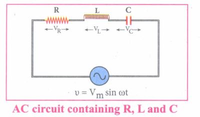
(ii) Let i be the resulting circuit current in the circuit at that instant. As a result, the voltage is developed across R, Land C.
(iii) We know that voltage across R (VR) is in phase with i, voltage across L (VL) leads i by \(\frac { \pi }{ 2 } \) and voltage across C (Vc) lags behind i by \(\frac { \pi }{ 2 } \)
(iv) The phasor diagram is drawn with current as the reference phasor. The current is represented by the phasor \(\vec { OI } \), VR by \(\vec { OA } \); VL by \(\vec { OB } \); Vc by \(\vec { OC } \) as shown in Figure.
(v) The length of these phasors are OI = Im, OA = ImR, OB = ImXL; OC = ImXC
The circuit is either effectively inductive or capacitive or resistive that depends on the value of VL or VC. Let us assume that VL>VC so that nef voltage drop across L-C combination is VL - VC which is represented by a phasor \(\vec { OD } \)
(vi) By parallelogram law, the diagonal \(\vec { OE } \) gives the resultant voltage ሀ of VR and (VL - VC) and its length OE is equal to Vm Therefore,
V2m = V2R + (VL - VC)2 = \(\sqrt { { ({ { I }_{ m }R) } }^{ 2 }+{ ({ I }_{ m }{ X }_{ L }-{ I }_{ m }{ X }_{ C }) }^{ 2 } }=I_m \sqrt {R^2+({X_L-X_C)}^2}\)
or \({ I }_{ m }=\frac { { V }_{ m } }{ \sqrt { R^{ 2 }+({ { X }_{ L }-{ X }_{ C }) }^{ 2 } } } \) ......(2)
\((or) { I }_{ m }=\frac { { V }_{ m } }{ Z } \) where z = \(\sqrt { { R }^{ 2 }+({ { X }_{ L }-{ X }_{ C }) }^{ 2 } } \) ......(3)
(vii) Z is called impedance of the circuit which refers to the effective opposition to the circuit current by the series RLC circuit. The voltage triangle and impedance triangle are given in the Figure.
.JPG)
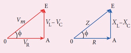
(viii) From phasor diagram, the phase angle between v and i is found out from the following relation
\(tan\phi =\frac { V_{ L }-{ V }_{ C } }{ { V }_{ R } } =\frac { X_{ L }-{ V }_{ C } }{ R } \)
Special cases:
(i) If XL > XC (XL - XC) is positive and phase angle \(\phi \) is also positive. It means that the applied voltage leads the current by \(\phi \) (or current lags behind voltage by \(\phi\)). The circuit is inductive.
∴v = Vm sin ωt; i = Im sin(ωt - \(\phi \))
(ii) If XL < XC (XL - XC) is negative and\(\phi \) is also negative. Therefore current leads voltage by \(\phi \) (or voltage lags behind current by\(\phi \)) and the circuit is capacitive.
∴ = Vm sin ωt; i = Im sin(ωt + \(\phi \))
(ii) If XL = XC \(\phi \) is zero. Therefore current and voltage are in the same phase and the circuit is resistive
∴v = Vm sin ωt, i = Im sinωt
6.
(i) Consider a circuit containing a pure inductor of inductance L connected across an alternating voltage source (Figure). The alternating voltage is given by the equation.
v = Vm sin ωt .......(1)
(ii) The alternating current flowing through the inductor induces a self-induced emf or back emf in the circuit. The back emf is given by
Back emf, ε = \(-L\frac{di}{dt}\)
By applying Kirchoff's loop rule to the purely inductive circuit, we get
v + ε =0
Vm sin ωt = L \(\frac{di}{dt}\)
di = \(\frac{V_m}{L}\) sin ωt dt
Integrating both sides, we get
i = \(\frac{V_m}{L}\) ഽ sin ωt dt
i = \(\frac{V_m}{L_ω}\) (-cos ωt) + constant
.JPG)
(iii) The integration constant in the above equation is independent of time. Since the voltage in the circuit has only time dependent part, we can set the time independent part in the current (integration constant) into zero.
\(i=\frac { { V }_{ m } }{ \omega L } { sin }\left( \omega t-\frac { \pi }{ 2 } \right) \) \(\left[ -{ cos\omega t=-sin\left( \frac { \pi }{ 2 } -\omega t \right) }\\ \because =sin\left( \omega t-\frac { \pi }{ 2 } \right) \right] \)
(or) \(i={ I }_{ m }sin\left( \omega t-\frac { \pi }{ 2 } \right) \) .....(2)
(iv) Where \(\frac { { V }_{ m } }{ \omega L } \) = Im the peak value of the alternating current in the circuit. From equation (1) and (2), it is evident that - current lags behind the applied voltage \(\frac { \pi }{ 2 } \) in an inductive circuit. This fact is depicted in the phasor diagram. In the wave diagram also, it is seen that current lags the voltage by 90° .
(v) Inductive reactance XL:
The peak value of current Im is given by Im = \(\frac { { V }_{ m } }{ \omega L } \). Let us compare this equation with Im = \(\frac { { V }_{ m } }{ R} \) from resistive circuit The quantity ωL plays the same role as the resistance in resistive circuit. This is the resistance offered by the inductor, called inductive reactance (XL) It is measured in ohm.
XL = ωL
.JPG)
7.
(i) There is a difficulty during power transmission. A sizable fraction of electric power is lost due to Joule heating (FR) in the transmission lines which are hundreds of kilometer long. This power loss can be tackled either by reducing current I or by reducing resistance R of the transmission lines. The resistance R can be reduced with thick wires of copper or aluminium. But this increases the cost of production of transmission lines and other related expenses. So this way of reducing power loss is not economically viable.
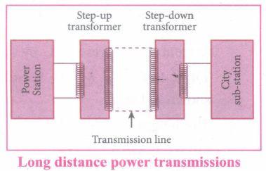
(ii) Since power produced is alternating in nature, there is a way out. The most important property of alternating voltage that it can be stepped up and stepped down by using transformers could be exploited in reducing current and thereby reducing power losses to a greater extent.
(iii) At the transmitting point, the voltage is increased and the corresponding current is decreased by using step-up transformer.
(iv) Then it is transmitted through transmission lines. This reduced current at high voltage reaches the destination without any appreciable loss.
Illustration:
An electric power of 2 MW is transmitted to a place through transmission lines of total resistance, say R = 40 Ω, at two different voltages. One is lower voltage (10 kV) and the other is higher (100 kV). Let us now calculate and compare power losses in these two cases.
Case (i):
\(P=2 \mathrm{MW} ; R=40 \Omega ; V=10 \mathrm{kV}\)
Power, P = V I
∴ Current, \(I=\frac{P}{V}=\frac{2 \times 10^6}{10 \times 10^3}=200 \mathrm{~A}\)
Power loss = Heat produced \(=\mathrm{I}^2 \mathrm{R}=(200)^2 \times 40=1.6 \times 10^6 \mathrm{~W}\)
\(% of power loss =\frac{1.6 \times 10^6}{2 \times 10^6} \times 100 \%\)\(\% of \ power \ loss =\frac{1.6 \times 10^6}{2 \times 10^6} \times 100 \%\)
\(=0.8 \times 100 \%=80 \%\)
Case (ii):
\(P=2 \mathrm{MW} ; R=40 \Omega ; V=100 \mathrm{kV} \)
\(\therefore \text {Current, } I=\frac{P}{V}=\frac{2 \times 10^5}{100 \times 10^3}=20 \mathrm{~A}\)
Power loss = PR= (20)2 x 40 = 0.016 x 10⁶ W
\(\% of \ power \ loss =\frac{0.01.6 \times 10^6}{2 \times 10^6} \times 100 \%\times 0.008 \%\times 100 \%=0.8\%\)
Thus, it is clear that when an electric power is transmitted at higher voltage, the power loss is reduced to a large extent.
8.
Principle:
The principle of transformer is the mutual induction between two coils. That is, when an electric current passing through a coil changes with time, an emf is induced in the neighbouring coil.
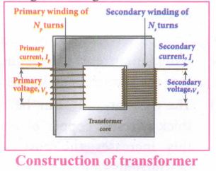
Construction:
(i) In the simple construction of transformers, there are two coils of high mutual inductance wound over the same transformer core.
(ii) The core is generally laminated and is made up of a good magnetic material like silicon steel. Coils are electrically insulated but magnetically linked via transformer core.
(iii) The coil across which alternating voltage is applied is called primary coil P and the coil from which output power is drawn out is called secondary coil S. The assembled core and coils are kept in a container which is filled with suitable medium for better insulation and cooling purpose.
Working:
(i) If the primary coil is connected to a source of alternating voltage, an alternating magnetic flux is set up in the laminated core.
(ii) If there is no magnetic flux leakage, then whole of magnetic flux linked with primary coil is also linked with secondary coil.
(iii) This means that rate at which magnetic flux changes through each turn is same for both primary and secondary coils.
(iv) As a result of flux change, emf is induced in both primary and secondary coils. The emf induced in the primary coil vp or back of εp is given by,
vp = εp = -Np \(\frac{dФ_B}{dt}\) ........(1)
(vi) The frequency of alternating magnetic flux in the core is same as the frequency of the applied voltage. Therefore, induced emf in secondary will also have same frequency as that of applied voltage. The emf induced in the secondary coil εs is given by ,
εs = -Ns\(\frac{dФ_B}{dt}\)
Where Np and Ns are the number of turns in the primary and secondary coil respectively. If the secondary circuit is open, then εs = ሀs where u is the voltage ሀs across secondary coil
ሀs = εs = -Ns \(\frac{dФ_B}{dt}\) ........(2)
From equations (1) and (2),
\(\frac{v_s}{v_p}=\frac{N_s}{N_p}\) = K ........(3)
(vii) This constant K is known as voltage transformation ratio. For an ideal transformer, input power vpip= Output power vsis
where ip and is are the currents in the primary and secondary coil respectively.
(ix) Therefore,
\(\frac{V_s}{V_p}=\frac{N_s}{N_p}=\frac{I_p}{I_s}\) ........(4)
Equation (4) is written in terms of amplitude of corresponding quantities
\(\frac{V_s}{V_p}=\frac{N_s}{N_p}=\frac{I_p}{I_s}\) = K
i) If Ns> Np (or K > 1), ∴ Vs > Vp and Is < Ip This is the case of step-up transformer in which voltage is increased and the corresponding current is decreased.
ii) If Ns< Np (or K < 1), ∴ Vs < Vp and Is > Ip This is step-down transformer where voltage is decreased and the current is increased.
Efficiency of a transformer:
The efficiency η of a transformer is defined as the ratio of the useful output power to the input power. Thus,
\(η=\frac{Outpur \ power}{Input \ power}\times100% \) % ....(5)
9.
(i) In some AC generators may have more than one coil in the armature core and each coil producesan alternating emf. In these generators, more than one emf is produced. Thus, they are called poly-phase generators.
(ii) If there are two alternating emfs produced in a generator, it is called two-phase generator, it is called two-phase generator. In some AC generators, there are three separate coils, which owould give three separate emfs. Hence, they are called three-phase AC generators.
(iii) In the simplified construction of three-phase AC generator, the armature core has 6 slots, cut on its inner rim. Each slot is 60° away from one another. Six armature conductors are mounted in these slots.The conductors 1 and 4 are joined in series to form coil 1. The conductors 3and 6 form coil 2 while the conductors 5 and 2 form coil 3. So, these coils arerectangular in shape and are 120° apart from one another.
(iv) The initial position of the field magnet is horizontal and field direction is perpendicular to the plane of the coil 1. As it is seen in single phase AC generator, when field magnet is rotated from that position in clockwise direction, alternating emf ε1 in coil 1 begins a cycle from origin O. This is shown in Figure.
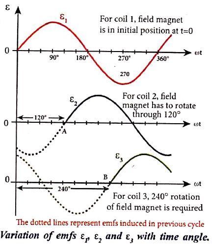
(v) The corresponding cycle for alternating emf ε2 in coil 2 starts at point A after field magnet has rotated through 120°. Therefore, the phase difference between ε1 and ε2 is 120°. Similarly, emf ε3 in coil 3 would begin its cycle at point B after 240° rotation of field magnet from initial position. Thus these emfs produced in the three phase AC generator have 120° phase difference between one another.
10.
.JPG)
Working: The loop PQRS is stationary and is perpendicular to the plane of the paper. When field windings are excited, magnetic field is produced around it. Let the field magnet be rotated in clockwise direction by some external means (Figure).
(i) Assume that initial position of the field magnet is horizontal. At that instant, the direction of magnetic field is perpendicular to the plane of the loop PQRS. The induced emf is zero. This is represented by origin O in the graph between induced emf and time angle.
(ii) When field magnet rotates through 90°, magnetic field becomes parallel to PQRS. The induced emfs across PQ and RS would become maximum. Since they are connected in series, emfs are added up and the direction of total induced emf is given by Flemin's right hand rule.
.JPG)
(iii) Care has to be taken while applying this rule, the thumb indicates the direction of the motion of the conductor with respect to field. For clockwise rotating poles, the conductor appears to be rotating anticlockwise. Hence, thumb should point to the left. The direction of the induced emf is at right angles to the plane of the paper. For PQ, it is inwards and for RS outwards. Therefore, the current flows along PQRS. The point A in the graph represents this maximum emf.
(iv) For the rotation of 180° from the initial position, the field is again perpendicular to PQRS and the induced emf becomes zero. This is represented by point B.
(v) The field magnet becomes again parallel to PQRS for 270° rotation of field magnet. The induced emf is maximum but the direction is reversed. Thus the current flows along SRQP. This is represented by point C
(vi) On completion of 360°, the induced emf becomes zero and is represented by the point D. From the graph, it is clear that emf induced in PQRS is alternating in nature.
(vii) Therefore, when field magnet completes one rotation, induced emf in PQRS finishes one cycle.
11.
Construction:
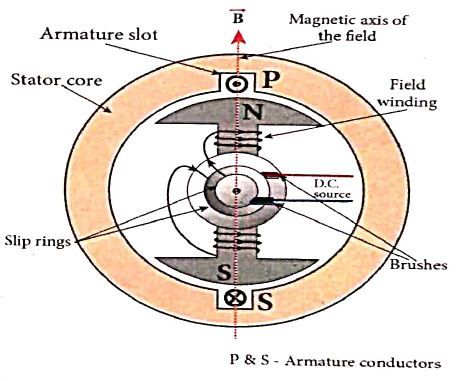
Alternator consists of two major parts, namely stator and rotor. As their names suggest, stator is stationary while rotor rotates inside the stator. In any standard construction of commercial alternators, the armature winding is mounted on stator and the field magnet on rotor.
The construction details of stator, rotor and various other components involved in them are given below.
(a) Stator:
The stationary part which has armature windings mounted in it is called stator. It has two components, namely stator frame, stator core and armature winding.
Stator core:
Stator core or armature core is made up of iron or steel alloy. It is a hollow cylinder and is laminated to minimize eddy current loss. The slots are cut on inner surface of the core to accommodate armature windings.
Armature winding:
Armature winding is the coil, wound on slots provided in the armature core.
(b) Rotor
Rotor contains magnetic field windings. The magnetic poles are magnetized by DC source. The ends of field windings are connected to a pair of slip rings, attached to a common shaft about which rotor rotates. Slip rings rotate along with rotor. To maintain connection between the DC source and field windings, two brushes are used which continuously slide over the slip rings.
12.
(i) Consider a rectangular coil of turns kept in a uniform magnetic field \(\vec{B}\) as shown in Figure (a). The coil rotates in anti-clockwise direction with an angular velocity ω about an axis, perpendicular to the field, and to the plane of the paper.
(ii) At time = 0, the plane of the coil is perpendicular to the field and the flux linked with the coil has its maximum value \({ \Phi }_{ m }=BA\) (where A is the area of the coil).
(iii) In a time t seconds, the coil is rotated through an angle θ (= ωt) in anti-clockwise direction. In this position, the flux linked is NBA cos ωt, is due to the component of B normal to the plane of the coil (Figure(b)). The component parallel to the plane (B sin ωt) has no role in electromagnetic induction. Therefore, the flux linkage with the coil at this deflected position is
NΦB = NBA cosθ = NBA cos ωt
According to Faraday's law, the emf induced at that instant is
.JPG)
\(ε=- \frac { d }{ dt } (N{ \Phi }_{ B })=-\frac { d }{ dt } (NBAcos\omega t)\)
= -NBA (-sin ωt)ω
= NBAω sin ωt
(iv) When the coil is rotated through 900 from initial position, sin ωt = 1. Then the maximum value of induced emf is
εm = NBAω
Therefore, the value of induced emf at that instant is then given by,
ε = εm sinωt ....(1)
.JPG)
(vii) It is seen that the induced emf varies as sine function of the time angle ωt. The graph between induced emf and time angle for one rotation of coil will be a sine curve (Figure) and the emf varying in this manner is called sinusoidal emf or alternating emf.
If this alternating voltage is given to a closed circuit, a sinusoidally varying current flows in it. This current is called alternating current and is given by,
i = Im sinωt ....(2)
Where, Im is the maximum value of induced current.
13.
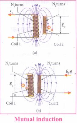
Consider two coils which are placed close to each other. If an electric current il is sent through coil 1, the magnetic field produced by it is also linked with coil 2 as shown in Figure (a). If Φ21 be the magnetic flux linked with each turn of the coil 2 of N2 turns due to current in coil 1, then the total flux linked with coil 2 (N2Φ21) is proportional to the current i1 in the coil 1.
N2Φ21 ∝ i1
N2Φ21 = M21 i1
(or) M21 = \(\frac { { N }_{ 2 }{ \Phi }_{ 21 } }{ { i }_{ 1 } } \)
The constant of proportionality M21 is the mutual inductance (or) co-efficient of mutual induction. If i1 = 1A then M21 = \({ N }_{ 2 }{ \Phi }_{ 21 }\).Therefore, the mutual inductance M21 is defined as the flux linkage of the coil 2 when 1A current flows through coil 1 of the coil 2 with respect to coil 1.
When the current i1 changes with time, an emf ε2 is induced in coil 2. From Faraday's law of electromagnetic induction, this mutually induced emf ε2 is given by
|
\({ \varepsilon }_{ 2 }=\frac { { d(N }_{ 2 }{ \Phi }_{ 21 }) }{ dt } =-\frac { d({ M }_{ 21 }{ i }_{ 1 }) }{ dt } \) |
The negative sign in the above equation shows that the mutually induced emf always opposes the change in current i1 with respect to time. If \(\frac { { di }_{ 1 } }{ dt } \) = 1 As-1, then M21= -ε2·
Mutual inductance M21 is also defined as the opposing emf induced in the coil 2 when the rate of change of current through the coil 1 is 1 As-1.
Similarly, if an electric current i2 through coil 2 changes with time, then emf ε1 is induced in coil 1. Therefore,
\({ M }_{ 12 }=\frac { {N }_{ 1 }{ \Phi }_{ 12 } }{ { i }_{ 2 } } \) and \({ M }_{ 12 }=\frac { -\varepsilon }{ \frac { { di }_{ 2 } }{ dt } } \)
where M12 is the mutual inductance of the coil 1 with respect to coil 2. It can be shown that for a given pair of coils, the mutual inductance is same.
i.e., M21= M12 = M
14.
Unit of Inductance:
Inductance is a scalar and its unit is Wb A-1 or Vs A-1. It is also measured in henry (H).
1 H = 1 Wb A-1 = 1 V sA-1
The dimensional formula of inductance is [ML2T-2A-2].
If i = 1 A and NФB = 1 Wb turns, then L = 1 H.
Therefore, the inductance of the coil is said to be one henry, if a current of 1 A produces unit flux linkage in the coil.
If \(\frac { di }{ dt } =1\) As-1 and ε = -1 V, then L = 1H
Therefore, One henry is defined as the inductance of the coil, if a current changing at the rate of 1 A s-1 induces an opposing emf of 1 V in it.
15.
(i) Self inductance of a coil is desined as the flux linkage with the coil, when a current of 1 A flows through it.
\(L=\frac{{ N\Phi }_{ B }}{i}\)
\(L={ N\Phi }_{ B }\)
(ii) Self inductance of a coil is defined as the opposing emf induced in the coil when the rate of change of current through the coil is 1 A s-1
\(\varepsilon =\frac { d{ (N\Phi }_{ B }) }{ dt } \)
\(=-\frac { d(Li) }{ dt }\)
\(\varepsilon =-L\frac { di }{ dt } \)
L = -e
16.
(a) Induction stove
(i) Induction stove is used to cook the food quickly and safely with less energy consumption. Below the cooking zone, there is a tightly wound coil of insulated wire.
(ii) The cooking pan made of suitable material, is placed over the cooking zone. When the stove is switched on, an alternating current flowing in the coil produces high frequency alternating magnetic field which induces very strong eddy currents in the cooking pan.
(iii) The eddy currents in the pan produce so much of heat due to Joule heating which is used to cook the food.
(b) Eddy current brake
(i) This eddy current braking system is generally used in high speed trains and roller coasters. Strong electromagnets are fixed just above the rails.
(ii) To stop the train, electromagnets are switched on. The magnetic field of these magnets induces eddy currents in the rails which oppose or resist the movement of the train. This is Eddy current linear brake.
(c) Eddy current testing
(i) It is one of the simple non-destructive testing methods to find defects like surface cracks, air bubbles present in a specimen.
(ii) A coil of insulated wire is given an alternating electric current, so that it produces an alternating magnetic field.
(iii) When this coil is brought near the test surface, eddy current is induced in the test surface.
(iv) The presence of defects causes the change in phase and amplitude of the eddy current that can be detected by some other means. In this way, the defects present in the specimen are identified.
(d) Electro magnetic damping:
(i) The armature of the galvanometer coil is wound on a soft iron cylinder.
(ii) Once the armature is deflected, the relative motion between the soft iron cylinder and the radial magnetic field induces eddy current in the cylinder.
(iii) The damping force due to the flow of eddy current brings the armature to rest immediately and then galvanometer shows a steady deflection. This is called electromagnetic damping.
17.
Conservation of energy:
(i) The truth of Lenz's law can be established on the basis of the law of conservation of energy. The explanation is as follows:
(ii) According to Lenz's law, when a magnet is moved either towards or away from a coil, the induced current produced opposes its motion
(iii) As a result, there will always be a resisting force on the moving magnet.
(iv) Work has to be done by some external agency to move the magnet against this resisting force
(v) Here the mechanical energy of the moving magnet is converted into the electrical energy which in turn, gets converted into Joule heat in the coil i.e., energy is converted from one form to another.
(vi) On the contrary to Lenz's law, let us assume that the induced current helps the cause responsible for its production.
(vii) Now When we push the magnet litle bit towards the coil, the induced current helps the movement of the magnet towards the coil.
(viii) Then the magnet starts moving towards the coil without any expense of energy. This, becomes a perpetual motion machine.
(ix) In practice, no such machine is possible. Therefore, the assumption that the induced current helps the cause is wrong.
18.
(i) Let us move a bar magnet towards the solenoid, with its north pole pointing the solenoid. This motion increases the magnetic flux of the coil which in turn, induces an electric current.
(ii) Due to the flow of induced current, the coil becomes a magnetic dipole whose two magnetic poles are on either end of the coil.
(iii) In this case, the cause producing the induced current is the movement of the magnet. According to Lenz's law, the induced current should flow in such a way that it opposes the movement of the north pole towards coil
(iv) It is possible if the end nearer to the magnet becomes north pole.
(v) Then it repels the north pole of the bar magnet and opposes the movement of the magnet. Once pole ends are known, the direction of the induced current could be found by using right hand thumb rule.
(vi) When the bar magnet is withdrawn, the nearer end becomes south pole which attracts north pole of the bar magnet, opposing the receding motion of the magnet.
(vii) Thus, the direction of the induced current can be found from Lenz's law.
19.
(i) Consider a closed circuit consisting of a coil C of insulated wire and a galvanometer G. The galvanometer does not indicate deflection as there is no electric current in the circuit.
(ii) When a bar magnet is inserted into the stationary coil, with its north pole facing the coil, there is a momentary deflection in the galvanometer. This indicates that an electric current is set up in the coil. If the magnet is kept stationary inside the coil, the galvanometer does not indicate deflection.
(iii) The bar magnet is now withdrawn from the coil, the galvanometer again gives a momentary deflection but in the opposite direction. So, the electric current flows in opposite direction. Now if the magnet is moved faster, it gives a larger deflection due to a greater current in the circuit.
(iv) The ar magnet is reversed, i.e., the south pole now faces the coil. When the above experiment is repeated, the deflections are opposite to that obtained in the case of north pole.
(v) If the magnet is kept stationary and the coil is moved towards or away from the coil, similar results are obtained. It is concluded that whenever there is a relative motion between the coil and the magnet, there is deflection in the galvanometer, indicating the electric current setup in the coil.
20.
Qualitative treatment:
The electromagnetic oscillations of LC system can be compared with the mechanical oscillations of a spring-mass system.
There are two forms of energy involved in LC oscillations. One is electrical energy of the charged capacitor, the other magnetic energy of the inductor carrying current.
Table: Energy in two oscillatory systems:
| LC oscillator | Spring-mass system | ||
| Element | Energy | Element | Energy |
| Capacitor | Electrical Energy \(=\frac{1}{2}\left(\frac{1}{\mathrm{C}}\right) q^{2}\) | Spring | Potential energy\(\frac{1}{2} k x^{2}\) |
| Inductor | Magnetic energy \(=\frac{1}{2} \mathrm{~Li}^2, i=\frac{dq}{dt}\) | Mass | Kinetic energy\(=\frac{1}{2} m v^{2},v=\frac{dx}{dt} \) |
Likewise, the mechanical energy of the spring-mass system exists in two forms; the potential energy of the compressed or extended spring and the kinetic energy of the mass. The Table lists these two pairs of energy.
By examining the table, the analogies between the various quantities can be understood and these correspondences are given in the Table.
The angular frequency of oscillations of a spring-mass is given by,
\(\omega= \sqrt \frac{k}{m}\)
From Table, k→ 1/C and m → L. Therefore, the angular frequency of LC oscillations is given by,
\(\omega= \frac{1} {\sqrt {LC}}\)
21.
| S.No | Name of the losses | Source of losses | Method to minimise |
| (i) | (a) Core loss (or) Iron loss (or) Hysteresis loss | Transformer core is magnetised and demagnetised repeatedly |
Using steel of high silicon content in making transformer core |
| (b) Eddy current loss | Alternating magnetic flux in the core induces eddy currents in it. |
Using very thin laminations of transformer core. | |
| (ii) | Copper loss | When the electric current flows through windings of transformers, some amount of energy is dissipated due to Joule heating |
Using wires of larger diameter |
| (iii) | Flux leakage | The magnetic lines of primary coil are not completely linked with secondary coil. |
Windings the coils one over the other. |
22.
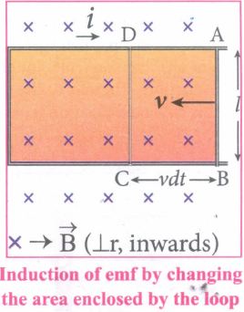
23.
Whenever a current is established in the circuit, the inductance opposes the growth of the current. In order to establish a current in the circuit, work is done against this opposition by some external agency. This work done is stored as magnetic potential energy.
Let us assume that electrical resistance of the inductor is negligible and inductor effect alone is considered. The induced emf ε at any instant t is
\(\varepsilon =-L\frac { di }{ dt } \) ......(1)
Let dW be work done in moving a charge dq in a time dt against the opposition, then
dW = -εdq
= -εidt (∵ dq= idt)
Substituting for ε from equation (1),∴
=-\(\left( -L\frac { di }{ dt } \right) \)idt
dW = Lidi
Total work done in establishing the current i is,
\(W=ഽdW=ഽ^i_0Lidt=\left( L\frac { i^2 }{ 2 } \right)^i_0 \)
W =\(\frac{1} {2}\)Li2
This work done is stored as magnetic potential energy.
UB = \(\frac{1} {2}\)Li2
The energy density is the energy stored per unit volume of the space and is given by
\({ u }_{ B }=\frac { { U }_{ B } }{ Al } \) (∵ Volume of the solenoid = Al)
| \({ u }_{ B }=\frac { { Li }^{ 2 } }{ 2Al } =\frac { ({ \mu }_{ \circ }{ n }^{ 2 }Al){ i }^{ 2 } }{ 2 } \) \(\because{L= { \mu }}_{ \circ }{ n }^{ 2 }Al\) \(=\frac { { \mu }_{ \circ }{ n }^{ 2 }{ i }^{ 2 } }{ 2 } \) \({ u }_{ B }=\frac { { B }^{ 2 } }{ 2{ \mu }_{ \circ } } \) \((\because B={ \mu }_{ \circ }ni)\) |
24.
Consider a long solenoid of length Iand cross-sectional area A. Let n be the number of turns per unit length (or turn density) of the solenoid. When an electric current i is passed through the solenoid, a magnetic field is produced by inside is almost uniform and is directed along the axis of the solenoid as shown in Figure. The magnetic field at any point inside the solenoid is given by,
B = μ0ni
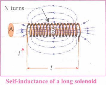
As this magnetic field passes through the solenoid, the windings of the solenoid are linked by the field lines. The magnetic flux passing through each turn is
\({ \phi }_{B }=\int _{ A }^{ }{\vec B.d } \vec { A } =BAcos\theta =BA(since\theta=0^o\)
= (μ0ni)A ....(1)
The total magnetic flux linked or flux linkage of the solenoid with N turns (the total number of turns N is given by N= n l) is
\({ N\Phi }_{ B }\) = (nl)(μ0ni)A
\({ N\Phi }_{ B }\) = (μon2Al)i ...(2)
The equation (1) is,
\({ N\Phi }_{ B }\) = Li
Comparing equation (1) and (2), we have
L =μn2Al ...(3)
From the above equation (3), it is clear that inductance depends on the geometry of the solenoid (turn density n, cross-sectional area A, length l) and the medium present inside the solenoid. If the solenoid is filled with a dielectric medium of relative permeability μr, then
L =μn2Al or L = μ0 μr n2 Al.
25.
Self inductance of a coil is the inductance that enables to poduce an opposing induced emf in it, when the current in the coil changes
Physical significances :
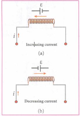
The inductance plays the same role in a circuit as mass and moment of inertia play at a mechanical motion. When a circuit is switched on, the increasing current induces an emf which opposes the growth of current in a circuit (Figure (a)). Likewise, when circuit is broken, the decreasing current induces an emf in the reverse direction. This emf now opposes the decay of current (Figure (b)).
Thus, the inductance of the coil opposes any change in current and tries to maintain the original state

12th Standard Syllabus & Materials
12th Standard
TN 12th Computer Applications வலையமைப்பு வடமிடல் Sample Question Papers Study Material - QB365 Set A
NEW12th Standard
TN 12th Computer Applications களப்பெயர் முறைமை (DNS) Sample Question Papers Study Material - QB365 Set A
NEW12th Standard
TN 12th Computer Applications வலையமைப்பு எடுத்துக்காட்டுகள் மற்றும் நெறிமுறைகள் Sample Question Papers Study Material - QB365 Set A
NEW12th Standard
TN 12th Computer Applications கணினி வலையமைப்பு ஓர் அறிமுகம் Sample Question Papers Study Material - QB365 Set A



Tamilnadu Stateboard 12th Standard Subjects

Maths

Chemistry
Physics

Biology

Computer Science

Business Maths and Statistics

Economics

Commerce

Accountancy

History

Computer Applications
Biology
Computer Technology
Computer Applications
Computer Science
Business Maths and Statistics
Commerce
Economics
Maths
Chemistry
Physics
Computer Technology
History
Accountancy

Tamil

English

French
Tamilnadu Stateboard Standards

