
 100% FREE ACCESS
12th Standard Syllabus & Materials
12th Standard
TN 12th Computer Applications மின்னணு தரவு பரிமாற்றம் Sample Question Papers Study Material - QB365 Set A
NEW12th Standard
TN 12th Computer Applications மின் - வணிக பாதுகாப்பு அமைப்புகள் Sample Question Papers Study Material - QB365 Set A
NEW12th Standard
TN 12th Computer Applications மின்னணு செலுத்தல் முறைகள் Sample Question Papers Study Material - QB365 Set A
NEW12th Standard
TN 12th Computer Applications மின் - வணிகம் Sample Question Papers Study Material - QB365 Set A
NEW12th Standard
TN 12th Computer Applications திறந்த மூல கருத்துருக்கள் Sample Question Papers Study Material - QB365 Set A
NEW12th Standard
TN 12th Computer Applications வலையமைப்பு வடமிடல் Sample Question Papers Study Material - QB365 Set A

Published on: 27/01/2021
12th Standard Physics English Medium Electromagnetic Induction and Alternating Current Reduced Syllabus Important Questions 2021
Download Tamil Nadu 12th Standard Physics question papers, model tests, one-mark questions, important questions, and public exam papers in PDF format. Free study materials and answer keys for TN State Board students.
Questions + Answers key
Take MCQ Physics Test1.
Three ac circuits in which equal amount of circuits are flowing. If the frequency of emf is increased how will the current the affected in these circuits? Give reason.
2.
A bar magnet is moved in the direction indicted by the arrow between two coils PQ and CD predict the directions of induced current in each coil.
3.
What is the signifienance of Quality factor or Q-factor.
4.
Write the application of series RLC resonant circut
5.
Distinguish between AC and DC.
6.
Explain the use of transformers in long distance transmission of electric power.
7.
When does power factor of a series RLC circuit become maximum?
8.
A closely wound circular coil of radius 0.02 m is placed perpendicular to the magnetic field. When the magnetic field is changed from 8000 T to 2000 T in 6 s, an emf of 44 V is induced in it. Calculate the number of turns in the coil. (Take π = \(\frac { 22 }{ 7 } \) )
9.
How will you define Q-factor?
10.
What are step-up and step-down transformers?
11.
Give the principle of AC generator.
12.
Mention the ways of producing induced emf.
13.
A straight conducting wire is dropped horizontally from a certain height with its length along east-west direction. Will an emf be induced in it? Justify your answer.
14.
A cylindrical bar magnet is kept along the axis of a circular solenoid. If the magnet is rotated about its axis, find out whether an electric current is induced in the coil.
15.
How does the capacitive reactance depend on frequency? & What is the reactance of a capacitor at hertz to the study at?
16.
Distinguish between average & rms value of an AC.
17.
A long solenoid having 400 turns per cm carries a current 2A. A 100 turn coil of cross-sectional area 4 cm2 is placed co-axially inside the solenoid so that the coil is in the field produced by the solenoid. Find the emf induced in the coil if the current through the solenoid reverses its direction in 0.04 sec.
18.
What do you understand by self - inductance of a coil? Give its physical significance.
19.
Find the impedance of a series RLC circuit if the inductive reactance, capacitive reactance and resistance are 184 Ω, 144 Ω and 30 Ω respectively.
20.
An ideal transformer has 460 and 40,000 turns in the primary and secondary coils respectively. Find the voltage developed per turn of the secondary if the transformer is connected to a 230 V AC mains. The secondary is given to a load of resistance 104 Ω. Calculate the power delivered to the load.
21.
In RLC series AC circuit at resonance __________.
Resistance is zero
Net reactance is zero
impedance is maximum
voltage leads the current by a phase angle \(\frac{ㅠ}{2}\)
22.
In LCR series circuit, at resonance is ___________
impedance (Z) is maximum
current is minimum
impedance (Z) is equal to R
vo = \(\frac{1}{LC}\)
23.
The power factor of an a.c, circuit is _________
\(\phi \)sin\(\phi \)
cosec \(\phi \)
cos \(\phi \)
tan \(\phi \)
24.
Unit of inductive reactance is ___________
ohm-metre
mho-metre-1
ohm
mho
25.
In a transformer, eddy current loss is minimized by using ____________.
laminated core made of muemetal
laminated core made of stelloy
shell type core
thick copper wire
26.
__________ principle is used in transformer.
mutual induction
electromagnetic induction
self induction
eddy currents
27.
The property of a coil which enables to produce an opposite induced emf in it when the current in the coil changes is called _______________
electromagnetism
self - induction
mutual induction
parallel- induction
28.
AC generator works on the principle of _____________.
self induction
mutual induction
electromagnetic induction
none of these
29.
A phenomenon in which a varying current in one coil induces an emf in the neighbouring coil is ___________.
mutual induction
self induction
electrostatic induction
electromagnetic induction
30.
If a secondary coil has 40 turns, and a primary coil with 20 turns is charged with 50V of potential difference, then potential difference in secondary would be ________________.
50 V
25 V
60 V
100 V
31.
Transformer works on _____________.
AC only
DC only
both AC and DC
AC more effectively than DC
32.
An emf of 12V is induced when the current in the coil changes at the rate of 40 A S-1. The coefficient of self induction of the coil is __________________.
0.3 H
0.003 H
30 H
4.8 H
33.
34.
When the current changes from +2A to −2A in 0.05 s, an emf of 8 V is induced in a coil. The co-efficient of self-induction of the coil is
0.2H
0.4H
0.8H
0.1H
35.
An electron moves on a straight line path XY as shown in the figure. The coil abcd is adjacent to the path of the electron. What will be the direction of current, if any, induced in the coil?
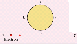
The current will reverse its direction as the electron goes past the coil
No current will be induced
abcd
adcb
36.
An AC generator consists of a coil of 1000 turns and cross sectional area of 100 cm2, rotating at an angular speed of 100 rpm in a uniform magnetic field of 1.6 x 10⁻² T calculate the maximum emf produced in the coil.
37.
An a.c voltage of 300V applied to the primary of a transformer & voltage of 3000V is obtained from the secondary coil. Calculate the ratio of circuit in the primary & secondary coils.
38.
Explain the mechanical analogy of LC oscillations by quantitative treatment.
39.
Derive an expression for phase angle between the applied voltage and current in a series RLC circuit.
40.
Explain the construction and working of transformer.
41.
Show mathematically that the rotation of a coil in a magnetic field over one rotation induces an alternating emf of one cycle. (or) Emf induced by changing relative orientation of the coil with the magnetic field.
42.
Define self-inductance of a coil interms of
(i) magnetic flux and
(ii) induced emf.
43.
Show that Lenz’s law is in accordance with the law of conservation of energy.
1.
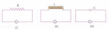
(i) R is not affected by frequency so current does not change on an increasing frequency.
(ii) Inductive reactance XL = 2π γL γ when frequency increases ~ increases and hence current in the circuit decreases.
(iii) Capacitive reactance Xc = \({ X }_{ c }=\frac { 1 }{ 2\pi \gamma c } \)
As the frequency ⋎ is increased, Xc decreases, and hence current increases.
2.
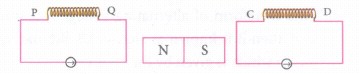
The current in the coil will flow clockwise the direction of current will be from P to Q in coil PQ and from C to D in coil CD.
3.
The current in the series RLC circuit becomes maximum at resonance. Due to the increase in current, the voltage across L and C are also increased. This magnification of voltages at series resonance is termed as Q-factor. It gives a measure of sharpness of current peak in the resanance condition of LCT circuit
4.
RLC circuits have many applications like filter circuits, oscillators, voltage multipliers, etc. An important use of series RLC resonant circuits is in the tuning circuits of radio and TV systems.
5.
|
AC |
DC |
|---|---|
| It is the current varying to the magnitude continuously and reverses the direction periodically. | The current and voltage in a DC system remain constant over a period of time and flows in the same fixed direction. |
| I = Im sin ωt | i = \(\frac{Q}{t}\) |
| The average value of AC over the complete cycle is zero. | The current is steady with respect to time. |
6.
At the transmitting point, the voltage is increased and the corresponding current is decreased by using a step-up transformer. Then it is transmitted through transmission lines. This reduced current at high voltage reaches the destination without any appreciable loss. At the receiving point, the voltage is decreased and the current is increased to appropriate values by using a step-down transformer, and then it is given to consumers.
7.
Power factor will be maximum, when Φ = 0 i.e., \(\tan ^{-1}\left(\frac{X_L-X_C}{R}\right)=0\)
\(\therefore X_L=X_C \Rightarrow L \omega=\frac{1}{C \omega} \)
\(\therefore \omega=\frac{1}{2 \pi \sqrt{L C}}\)
∴ Current I be max \(I_m=\frac{V_m}{R}\)
Hence power factor of a RLC series circuit becomes maximum, when
(i) \(X_L=X_C\)
(ii) Current \(I_m=\frac{V_m}{R}\) will be maximum
(iii) Frequency \(\omega_r=\frac{1}{2 \pi \sqrt{L C}}\)
8.
Change in magnetic field, dB = (8000 - 2000) = 6000 Wb
Change in time, dt = 6s
Radius of the coil, r = 2 x 10⁻² m
Induced emf, e = 44 V,
Area of the coil A =πr2 = \(\frac { 22 }{ 7 } \) x (2 x 10⁻²)2
= 12.56 x 10⁻⁴ m2
∴ Number of turns in the coil,
\(N=\frac { e }{ A\frac {dB}{dt }} \frac{44}{12.56\times10^{-4} \times(6000/6)}\)
\(N=\frac { 44 \times10 }{12.56 }=3.503\times10=35 \)
∴ Number of turns in the coil = 35
9.
Q factor is defined as the ratio of voltage across L or C to resonance to the applied voltage
Q - factor = \(\frac{Voltage \ across \ L \ or \ C \ resonance }{Applied \ voltage}\)
\(Q-factor=\frac{X_{L}}{R}=\frac{1}{R}\sqrt\frac{{L}}{C}\)
10.
(i) If Ns>Np(K>1),thenVs>Vp and Is
11.
AC generator work on the principle of electromagnetic induction. The relative motion between a conductor and a magnetic field changes the magnetic flux linked with the conductor which in turn, induces an emf
12.
Emf can be produced by changing magnetic flux in any of the following ways:
(i) By changing the magnetic field B
(ii) By changing the area A of the coil and
(iii) By changing the relative orientation θ of the coil with magnetic field.
13.
Yes! An emf will be induced in the wire because it moves perpendicular to the horizontal component of Earth’s magnetic field and hence it cuts the magnetic lines of Earth's magnetic field.
14.
The magnetic field of a cylindrical magnet is symmetrical about its axis. As the magnet is rotated along the axis of the solenoid, there is no induced current in the solenoid because the flux linked with the solenoid does not change due to the rotation of the magnet.
15.
Current leads the applied voltage by \(\frac{\pi}{2}\) in a capacitive circuit.
This is the resistance offered by the capacitor, called capacitive reactance (Xc). It measured in ohm.
\({ X }_{ c }=\frac { 1 }{ \omega C } \)
The capacitive reactance (Xc) varies inversely as the frequency. For a steady current, f = 0
∴\({ X }_{ c }=\frac { 1 }{ \omega C } -\frac { 1 }{ 2\pi fC } =\frac { 1 }{ 0 } =\infty \)
Thus a capacitive circuit offers infinite resistance to the steady current.
16.
|
Average value |
RMS value |
|---|---|
| The average value of alternating current is defined as the average of all values of current over a positive half-cycle or negative half-cycle. | The root means a square value of an alternating current is defined as the square root of the mean of the squares of all currents over one cycle. |
| Average value of AC, Iav = \(\frac { 2{ I }_{ m } }{ \pi } \) | \(\frac { { I }_{ m } }{ { \sqrt { 2 } } } \) |
| Iav = 0.6371m | Irms = 0.707Vm |
17.
\(N_1 =4 \times 10^4, \mathrm{~N}_2=100, \mathrm{I}=2 \mathrm{~A}, \mathrm{~A}=4 \times 10^{-4} \mathrm{~m}^2 \)
\(\mathrm{t} =0.04 \mathrm{~s}, \mathrm{e}=? \)
\(\mathrm{~B} =\mu_0 \mathrm{n}_1 \mathrm{I}=\frac{\mu_0 \mathrm{~N}_1 \mathrm{I}}{l}=\frac{4 \pi \times 10^{-7} \times 4 \times 10^4 \times 2}{1} \)
\(\mathrm{~B} =100.48 \times 10^{-3} \mathrm{~T} \)
\(\phi =\mathrm{BA}=100.48 \times 10^{-3} \times 4 \times 10^{-4} \)
\(\therefore \phi_1 =\phi_2=\phi=401.92 \times 10^{-7} \mathrm{wb} \)
\(\mathrm{d} \phi =\phi_1-\left(-\phi_2\right)=2 \phi=2 \times 401.92 \times 10^{-7} \)
\(\therefore \mathrm{d} \phi =803.84 \times 10^{-7} \mathrm{wb}\)
EMF induced in the coil,
\(e=-N_2 \frac{d \phi}{d t} \)
\(e=\frac{-100 \times 803.84 \times 10^{-7}}{0.04}=-200.96 \times 10^{-3} \mathrm{~V}\)
\(e=-0.2 \mathrm{~V}\)
18.
Self inductance of a coil is the inductance that enables to poduce an opposing induced emf in it, when the current in the coil changes
Physical significances :
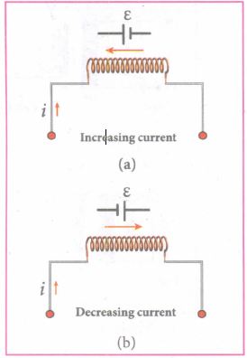
The inductance plays the same role in a circuit as mass and moment of inertia play at a mechanical motion. When a circuit is switched on, the increasing current induces an emf which opposes the growth of current in a circuit (Figure (a)). Likewise, when circuit is broken, the decreasing current induces an emf in the reverse direction. This emf now opposes the decay of current (Figure (b)).
Thus, the inductance of the coil opposes any change in current and tries to maintain the original state
19.
XL = 184 Ω; XC = 144 Ω
R = 30 Ω
(i ) The impedance is
\(Z=\sqrt { { R }^{ 2 }+{ \left( { X }_{ L }-{ X }_{ C } \right) }^{ 2 } } \)
\(=\sqrt { { 30 }^{ 2 }+{ (184-144) }^{ 2 } } \)
\(=\sqrt { 900+1600 } \)
Z = 50Ω
\(\text { (ii) } \phi =\tan ^{-1}\left(\frac{X_1-X_c}{R}\right) \)
\( \phi =\tan ^{-1}\left(\frac{184-144}{30}\right) \)
\(\phi =53.1^{\circ} \)
20.
NP = 460 turns; NS = 40,000 turns
VP = 230 V; RS = 104 Ω
(i) Secondary voltage,
\({ V }_{ s }=\frac { { V }_{ p }{ N }_{ s } }{ { N }_{ p } } =\frac { 230\times 40,000 }{ 460 } \)
= 20,000V
Secondary voltage per turn,\(\frac { { V }_{ S } }{ { N }_{ S } } =\frac { 20,000 }{ 40,000 } =0.5V\)
(ii) Power delivered
= \({ V }_{ s }{ I }_{ s }=\frac { { V }_{ s }^{ 2 } }{ { R }_{ s } } =\frac { 20,000\times 20,000 }{ { 10 }^{ 4 } } =40kW\)
21.
(b)
Net reactance is zero
22.
(c)
impedance (Z) is equal to R
23.
(c)
cos \(\phi \)
24.
(c)
ohm
25.
(b)
laminated core made of stelloy
26.
(b)
electromagnetic induction
27.
(b)
self - induction
28.
(c)
electromagnetic induction
29.
(a)
mutual induction
30.
(d)
100 V
31.
(a)
AC only
32.
(a)
0.3 H
33.
(a)
34.
\(\text {emf } e=8 \mathrm{~V} \)
\(d I=I_1-I_0=2-(-2)=4 \mathrm{~A} \)
\(\text {dt }=0.05 \mathrm{~s} \)
\(L=\frac{-e}{d I / d t}=\frac{-8}{4 / 0.05} \)
\(=\frac{-8 \times 0.05}{4}=\frac{-0.40}{4} \)
=-0.1 H
-ve sign indicates that self-induced emf always opposes the current w.r.t. time.
35.
The direction of conventional current is always opposite to the direction of flow of electrons.
36.
Given: N = 1000
A = 100 cm2 = 10-2 m2
v = 100 rpm = \(\frac{100}{60}\) rps
B = 3.6 x 10⁻²⁷
em = ?
em = NBAω = NBA (2πγ)
= 1000 x 3.6 x 10-2 x 10-2 x 2 x \(\frac{22}{7}\times\frac{100}{60}\)
e = 5.77 V
37.
Given :Primary voltage E1 = 300 V
Secondary voltage E2 = 3000 V
To find:
Primary current I1 = ?
Secondary current I2 = ?
Solution:
\(\frac { { I }_{ 1 } }{ { I }_{ 2 } } =\frac { { E }_{ 2 } }{ { E }_{ 1 } } =\frac { 3000 }{ 300 } \) = 10 : 1
38.
(i) The energy E remains constant for varying values of x and v. Differentiating E with respect to time, we get \(\frac { dE }{ dt } =\frac { 1 }{ 2 } \left( 2v\frac { dv }{ dt } \right) +\frac { 1 }{ 2 } k\left( \frac { dx }{ dt } \right) =0\)
or m \(\frac { { d }^{ 2 }x }{ { dt }^{ 2 } } +kx=0\)
since \(\frac { dx }{ dt } =\nu \) and \(\frac { dv }{ dt } =\frac { { d }^{ 2 }x }{ d{ t }^{ 2 } } \)
(ii) This is the differential equation of the oscillations of the spring-mass system. The general solution of an equation is of the form
x(t) = Xm cos (ωt + Φ)
where X is the maximum value of x(t), ω the angular frequency, and Φ the phase constant.
(iii) Similarly, the electromagnetic energy of the LC system is given by
\(U=\frac { 1 }{ 2 } { Li }^{ 2 }+\frac { 1 }{ 2 } \left( \frac { 1 }{ C } \right) { q }^{ 2 }\) = constant
Differentiating U with respect to time, we get
\(\frac { dU }{ dt } =\frac { 1 }{ 2 } L\left( 2i\frac { di }{ dt } \right) +\frac { 1 }{ 2C } \left( 2q\frac { dq }{ dt } \right) =0\)
(or) \(\frac { { d }^{ 2 }q }{ { dt }^{ 2 } } +\frac { 1 }{ C } q=0\) ....(1)
since \(i=\frac { dq }{ dt } \frac { di }{ dt } =\frac { { d }^{ 2 }q }{ d{ t }^{ 2 } } \)
(iv) The general solution of equation (1) is of the form
q(t) = Qm cos (ωt + Φ)
(v) where Qm is the maximum value of q(t), ω the angular frequency, and Φ the phase constant.
39.
(i) Consider a circuit containing a resistor of resistance R, a inductor of inductance L and a capacitor of capacitance C connected across an alternating voltage source (Figure ). The instantaneous value of the alternating voltage is given by the equation
ሀ = Vm sin ωt ......(1)
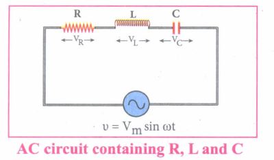
(ii) Let i be the resulting circuit current in the circuit at that instant. As a result, the voltage is developed across R, Land C.
(iii) We know that voltage across R (VR) is in phase with i, voltage across L (VL) leads i by \(\frac { \pi }{ 2 } \) and voltage across C (Vc) lags behind i by \(\frac { \pi }{ 2 } \)
(iv) The phasor diagram is drawn with current as the reference phasor. The current is represented by the phasor \(\vec { OI } \), VR by \(\vec { OA } \); VL by \(\vec { OB } \); Vc by \(\vec { OC } \) as shown in Figure.
(v) The length of these phasors are OI = Im, OA = ImR, OB = ImXL; OC = ImXC
The circuit is either effectively inductive or capacitive or resistive that depends on the value of VL or VC. Let us assume that VL>VC so that nef voltage drop across L-C combination is VL - VC which is represented by a phasor \(\vec { OD } \)
(vi) By parallelogram law, the diagonal \(\vec { OE } \) gives the resultant voltage ሀ of VR and (VL - VC) and its length OE is equal to Vm Therefore,
V2m = V2R + (VL - VC)2 = \(\sqrt { { ({ { I }_{ m }R) } }^{ 2 }+{ ({ I }_{ m }{ X }_{ L }-{ I }_{ m }{ X }_{ C }) }^{ 2 } }=I_m \sqrt {R^2+({X_L-X_C)}^2}\)
or \({ I }_{ m }=\frac { { V }_{ m } }{ \sqrt { R^{ 2 }+({ { X }_{ L }-{ X }_{ C }) }^{ 2 } } } \) ......(2)
\((or) { I }_{ m }=\frac { { V }_{ m } }{ Z } \) where z = \(\sqrt { { R }^{ 2 }+({ { X }_{ L }-{ X }_{ C }) }^{ 2 } } \) ......(3)
(vii) Z is called impedance of the circuit which refers to the effective opposition to the circuit current by the series RLC circuit. The voltage triangle and impedance triangle are given in the Figure.
.JPG)
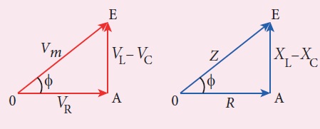
(viii) From phasor diagram, the phase angle between v and i is found out from the following relation
\(tan\phi =\frac { V_{ L }-{ V }_{ C } }{ { V }_{ R } } =\frac { X_{ L }-{ V }_{ C } }{ R } \)
Special cases:
(i) If XL > XC (XL - XC) is positive and phase angle \(\phi \) is also positive. It means that the applied voltage leads the current by \(\phi \) (or current lags behind voltage by \(\phi\)). The circuit is inductive.
∴v = Vm sin ωt; i = Im sin(ωt - \(\phi \))
(ii) If XL < XC (XL - XC) is negative and\(\phi \) is also negative. Therefore current leads voltage by \(\phi \) (or voltage lags behind current by\(\phi \)) and the circuit is capacitive.
∴ = Vm sin ωt; i = Im sin(ωt + \(\phi \))
(ii) If XL = XC \(\phi \) is zero. Therefore current and voltage are in the same phase and the circuit is resistive
∴v = Vm sin ωt, i = Im sinωt
40.
Principle:
The principle of transformer is the mutual induction between two coils. That is, when an electric current passing through a coil changes with time, an emf is induced in the neighbouring coil.
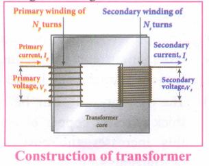
Construction:
(i) In the simple construction of transformers, there are two coils of high mutual inductance wound over the same transformer core.
(ii) The core is generally laminated and is made up of a good magnetic material like silicon steel. Coils are electrically insulated but magnetically linked via transformer core.
(iii) The coil across which alternating voltage is applied is called primary coil P and the coil from which output power is drawn out is called secondary coil S. The assembled core and coils are kept in a container which is filled with suitable medium for better insulation and cooling purpose.
Working:
(i) If the primary coil is connected to a source of alternating voltage, an alternating magnetic flux is set up in the laminated core.
(ii) If there is no magnetic flux leakage, then whole of magnetic flux linked with primary coil is also linked with secondary coil.
(iii) This means that rate at which magnetic flux changes through each turn is same for both primary and secondary coils.
(iv) As a result of flux change, emf is induced in both primary and secondary coils. The emf induced in the primary coil vp or back of εp is given by,
vp = εp = -Np \(\frac{dФ_B}{dt}\) ........(1)
(vi) The frequency of alternating magnetic flux in the core is same as the frequency of the applied voltage. Therefore, induced emf in secondary will also have same frequency as that of applied voltage. The emf induced in the secondary coil εs is given by ,
εs = -Ns\(\frac{dФ_B}{dt}\)
Where Np and Ns are the number of turns in the primary and secondary coil respectively. If the secondary circuit is open, then εs = ሀs where u is the voltage ሀs across secondary coil
ሀs = εs = -Ns \(\frac{dФ_B}{dt}\) ........(2)
From equations (1) and (2),
\(\frac{v_s}{v_p}=\frac{N_s}{N_p}\) = K ........(3)
(vii) This constant K is known as voltage transformation ratio. For an ideal transformer, input power vpip= Output power vsis
where ip and is are the currents in the primary and secondary coil respectively.
(ix) Therefore,
\(\frac{V_s}{V_p}=\frac{N_s}{N_p}=\frac{I_p}{I_s}\) ........(4)
Equation (4) is written in terms of amplitude of corresponding quantities
\(\frac{V_s}{V_p}=\frac{N_s}{N_p}=\frac{I_p}{I_s}\) = K
i) If Ns> Np (or K > 1), ∴ Vs > Vp and Is < Ip This is the case of step-up transformer in which voltage is increased and the corresponding current is decreased.
ii) If Ns< Np (or K < 1), ∴ Vs < Vp and Is > Ip This is step-down transformer where voltage is decreased and the current is increased.
Efficiency of a transformer:
The efficiency η of a transformer is defined as the ratio of the useful output power to the input power. Thus,
\(η=\frac{Outpur \ power}{Input \ power}\times100% \) % ....(5)
41.
(i) Consider a rectangular coil of turns kept in a uniform magnetic field \(\vec{B}\) as shown in Figure (a). The coil rotates in anti-clockwise direction with an angular velocity ω about an axis, perpendicular to the field, and to the plane of the paper.
(ii) At time = 0, the plane of the coil is perpendicular to the field and the flux linked with the coil has its maximum value \({ \Phi }_{ m }=BA\) (where A is the area of the coil).
(iii) In a time t seconds, the coil is rotated through an angle θ (= ωt) in anti-clockwise direction. In this position, the flux linked is NBA cos ωt, is due to the component of B normal to the plane of the coil (Figure(b)). The component parallel to the plane (B sin ωt) has no role in electromagnetic induction. Therefore, the flux linkage with the coil at this deflected position is
NΦB = NBA cosθ = NBA cos ωt
According to Faraday's law, the emf induced at that instant is
.JPG)
\(ε=- \frac { d }{ dt } (N{ \Phi }_{ B })=-\frac { d }{ dt } (NBAcos\omega t)\)
= -NBA (-sin ωt)ω
= NBAω sin ωt
(iv) When the coil is rotated through 900 from initial position, sin ωt = 1. Then the maximum value of induced emf is
εm = NBAω
Therefore, the value of induced emf at that instant is then given by,
ε = εm sinωt ....(1)
.JPG)
(vii) It is seen that the induced emf varies as sine function of the time angle ωt. The graph between induced emf and time angle for one rotation of coil will be a sine curve (Figure) and the emf varying in this manner is called sinusoidal emf or alternating emf.
If this alternating voltage is given to a closed circuit, a sinusoidally varying current flows in it. This current is called alternating current and is given by,
i = Im sinωt ....(2)
Where, Im is the maximum value of induced current.
42.
(i) Self inductance of a coil is desined as the flux linkage with the coil, when a current of 1 A flows through it.
\(L=\frac{{ N\Phi }_{ B }}{i}\)
\(L={ N\Phi }_{ B }\)
(ii) Self inductance of a coil is defined as the opposing emf induced in the coil when the rate of change of current through the coil is 1 A s-1
\(\varepsilon =\frac { d{ (N\Phi }_{ B }) }{ dt } \)
\(=-\frac { d(Li) }{ dt }\)
\(\varepsilon =-L\frac { di }{ dt } \)
L = -e
43.
Conservation of energy:
(i) The truth of Lenz's law can be established on the basis of the law of conservation of energy. The explanation is as follows:
(ii) According to Lenz's law, when a magnet is moved either towards or away from a coil, the induced current produced opposes its motion
(iii) As a result, there will always be a resisting force on the moving magnet.
(iv) Work has to be done by some external agency to move the magnet against this resisting force
(v) Here the mechanical energy of the moving magnet is converted into the electrical energy which in turn, gets converted into Joule heat in the coil i.e., energy is converted from one form to another.
(vi) On the contrary to Lenz's law, let us assume that the induced current helps the cause responsible for its production.
(vii) Now When we push the magnet litle bit towards the coil, the induced current helps the movement of the magnet towards the coil.
(viii) Then the magnet starts moving towards the coil without any expense of energy. This, becomes a perpetual motion machine.
(ix) In practice, no such machine is possible. Therefore, the assumption that the induced current helps the cause is wrong.

12th Standard Syllabus & Materials
12th Standard
TN 12th Computer Applications களப்பெயர் முறைமை (DNS) Sample Question Papers Study Material - QB365 Set A
NEW12th Standard
TN 12th Computer Applications வலையமைப்பு எடுத்துக்காட்டுகள் மற்றும் நெறிமுறைகள் Sample Question Papers Study Material - QB365 Set A
NEW12th Standard
TN 12th Computer Applications கணினி வலையமைப்பு ஓர் அறிமுகம் Sample Question Papers Study Material - QB365 Set A
NEW12th Standard
TN 12th Computer Applications PHP-உடன் MySQL-ஐ இணைத்தல் Sample Question Papers Study Material - QB365 Set A



Tamilnadu Stateboard 12th Standard Subjects

Maths

Chemistry
Physics

Biology

Computer Science

Business Maths and Statistics

Economics

Commerce

Accountancy

History

Computer Applications
Biology
Computer Technology
Computer Applications
Computer Science
Business Maths and Statistics
Commerce
Economics
Maths
Chemistry
Physics
Computer Technology
History
Accountancy

Tamil

English

French
Tamilnadu Stateboard Standards

