
 100% FREE ACCESS
12th Standard Syllabus & Materials
12th Standard
TN 12th Computer Applications மின்னணு தரவு பரிமாற்றம் Sample Question Papers Study Material - QB365 Set A
NEW12th Standard
TN 12th Computer Applications மின் - வணிக பாதுகாப்பு அமைப்புகள் Sample Question Papers Study Material - QB365 Set A
NEW12th Standard
TN 12th Computer Applications மின்னணு செலுத்தல் முறைகள் Sample Question Papers Study Material - QB365 Set A
NEW12th Standard
TN 12th Computer Applications மின் - வணிகம் Sample Question Papers Study Material - QB365 Set A
NEW12th Standard
TN 12th Computer Applications திறந்த மூல கருத்துருக்கள் Sample Question Papers Study Material - QB365 Set A
NEW12th Standard
TN 12th Computer Applications வலையமைப்பு வடமிடல் Sample Question Papers Study Material - QB365 Set A

Published on: 27/01/2021
12th Standard Physics English Medium Electromagnetic Induction and Alternating Current Reduced Syllabus Important Questions With Answer Key 2021
Download Tamil Nadu 12th Standard Physics question papers, model tests, one-mark questions, important questions, and public exam papers in PDF format. Free study materials and answer keys for TN State Board students.
Questions + Answers key
Take MCQ Physics Test1.
Three ac circuits in which equal amount of circuits are flowing. If the frequency of emf is increased how will the current the affected in these circuits? Give reason.
2.
A rectangular loop of wire is moved within the region of a uniform magnetic field acting perpendicular to its plane. What is the direction and magnitude of current induced in it?
3.
A bar magnet is moved in the direction indicted by the arrow between two coils PQ and CD predict the directions of induced current in each coil.
4.
What is the signifienance of Quality factor or Q-factor.
5.
Explain the use of transformers in long distance transmission of electric power.
6.
A fan of metal blades of length 0.4 m rotates normal to a magnetic field of 4 x 10 -3 T. If the induced emf between the centre and edge of the blade is 0.02 V, determine the rate of rotation of the blade.
7.
A rectangular coil of area 6 cm2 having 3500 turns is kept in a uniform magnetic field of 0.4 T. Initially, the plane of the coil is perpendicular to the field and is then rotated through an angle of 180o . If the resistance of the coil is 35 Ω, find the amount of charge flowing through the coil.
8.
A straight metal wire crosses a magnetic field of flux 4 mWb in a time 0.4 s. Find the magnitude of the emf induced in the wire.
9.
How will you define RMS value of an alternating current?
10.
List out the advantages of stationary armature-rotating field system of AC generator.
11.
What do you mean by self-induction?
12.
Mention the ways of producing induced emf.
13.
State Fleming’s right hand rule.
14.
The self-inductance of an air-core solenoid is 4.8 mH. If its core is replaced by iron core, then its self-inductance becomes 1.8 H. Find out the relative permeability of iron.
15.
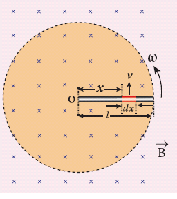
A copper rod of length l rotates about one of its ends with an angular velocity ω in a magnetic field B as shown in the figure. The plane of rotation is perpendicular to the field. Find the emf induced between the two ends of the rod.
16.
A closed coil of 40 turns and of area 200 cm2, is rotated in a magnetic field of flux density 2 Wb m–2. It rotates from a position where its plane makes an angle of 30o with the field to a position perpendicular to the field in a time 0.2 s. Find the magnitude of the emf induced in the coil due to its rotation.
17.
A circular antenna of area 3 m2 is installed at a place in Madurai. The plane of the area of antenna is inclined at 47o with the direction of Earth’s magnetic field. If the magnitude of Earth’s field at that place is 4.1 x 10⁻⁵ T find the magnetic flux linked with the antenna.
18.
What do you understand by self - inductance of a coil? Give its physical significance.
19.
A rectangular coil of area 70 cm2 having 600 turns rotates about an axis perpendicular to a magnetic field of 0.4 Wb m–2. If the coil completes 500 revolutions in a minute, calculate the instantaneous emf when the plane of the coil is
(i) perpendicular to the field
(ii) parallel to the field and
(iii) inclined at 60o with the field.
20.
21.
In an a.c. circuit with an inductor ______________.
voltage lags current by π/2
voltage and current are in phase
voltage leads current by π
current lags voltage by π/2
22.
A transformer is _____________.
converts energy
changes voltage
changes current
changes both current and voltage
23.
The necessary magnetic field for a low power a.c generator is produced by _________
electric coil
permanent magnets
electromagnets
batteries
24.
The property of a coil which enables to produce an opposite induced emf in it when the current in the coil changes is called _______________
electromagnetism
self - induction
mutual induction
parallel- induction
25.
Eddy currents was first observed by ________________.
Foucault
Newton
Faraday
Fleming
26.
If two coils are wound on a soft iron core the mutual induction is ______________.
small
very large
infinity
zero
27.
A phenomenon in which a varying current in one coil induces an emf in the neighbouring coil is ___________.
mutual induction
self induction
electrostatic induction
electromagnetic induction
28.
The self inductance of a coil is ________________.
directly proportional to N
inversely proportional to N
directly proportional to N2
inversely proportional to N2
29.
In Fleming's right hand rule, the forefinger represents the direction of ____________.
motion of the conductor
magnetic field
induced current
induced emf
30.
An emf of 12V is induced when the current in the coil changes at the rate of 40 A S-1. The coefficient of self-induction of the coil is _______________.
0.3 H
0.003 H
30 H
4.8 H
31.
In an oscillating LC circuit, the maximum charge on the capacitor is Q. The charge on the capacitor when the energy is stored equally between the electric and magnetic fields is
\(\frac{Q}{2}\)
\(\frac{Q}{\sqrt3}\)
\(\frac{Q}{\sqrt2}\)
Q
32.
In a series resonant RLC circuit, the voltage across 100 Ω resistor is 40 V. The resonant frequency ω is 250 rad/s. If the value of C is 4 µF, then the voltage across L is
600 V
4000 V
400 V
1 V
33.
34.
A circular coil with a cross-sectional area of 4 cm2 has 10 turns. It is placed at the centre of a long solenoid that has 15 turns/cm and a cross-sectional area of 10 cm2. The axis of the coil coincides with the axis of the solenoid. What is their mutual inductance?
7.54 μH
8.54 μH
9.54 μH
10.54 μH
35.
When the current changes from +2A to −2A in 0.05 s, an emf of 8 V is induced in a coil. The co-efficient of self-induction of the coil is
0.2H
0.4H
0.8H
0.1H
36.
An AC generator consists of a coil of 1000 turns and cross sectional area of 100 cm2, rotating at an angular speed of 100 rpm in a uniform magnetic field of 1.6 x 10⁻² T calculate the maximum emf produced in the coil.
37.
What is the self - inductance of a solenoid of length 40cm, area of cross - section 20cm2 and total number of turns is 800?
38.
The magnetic flux through a coil perpendicular to the plane is given by Φ = 5t3 +4t2 +2t calculate the induced emf through the coil at t = 2S
39.
A magnetic field of flux density 10T alts normally to the coil of 50 turns having 100cm2 area. Find emf induced, if the coil is removed fro the magnetic field in 0.15S.
40.
Obtain an expression for average power of AC over a cycle. Discuss its special cases.
41.
Show mathematically that the rotation of a coil in a magnetic field over one rotation induces an alternating emf of one cycle. (or) Emf induced by changing relative orientation of the coil with the magnetic field.
42.
Give the uses of Foucault current.
43.
Establish the fact that the relative motion between the coil and the magnet induces an emf in the coil of a closed circuit.
1.
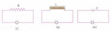
(i) R is not affected by frequency so current does not change on an increasing frequency.
(ii) Inductive reactance XL = 2π γL γ when frequency increases ~ increases and hence current in the circuit decreases.
(iii) Capacitive reactance Xc = \({ X }_{ c }=\frac { 1 }{ 2\pi \gamma c } \)
As the frequency ⋎ is increased, Xc decreases, and hence current increases.
2.
If the loop moves within the region of a uniform magnetic field no current will be induced in the loop. Hence no direction.
3.
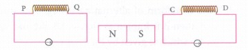
The current in the coil will flow clockwise the direction of current will be from P to Q in coil PQ and from C to D in coil CD.
4.
The current in the series RLC circuit becomes maximum at resonance. Due to the increase in current, the voltage across L and C are also increased. This magnification of voltages at series resonance is termed as Q-factor. It gives a measure of sharpness of current peak in the resanance condition of LCT circuit
5.
At the transmitting point, the voltage is increased and the corresponding current is decreased by using a step-up transformer. Then it is transmitted through transmission lines. This reduced current at high voltage reaches the destination without any appreciable loss. At the receiving point, the voltage is decreased and the current is increased to appropriate values by using a step-down transformer, and then it is given to consumers.
6.
Magnetic field B = 4 x 10⁻³ T
Induced emf, e = 0.02V = 2 x 10⁻² V
Length of a blade, I= 0,4; m = 4 x 10⁻¹ m
Change in magnetic flux, dΦ = Bds
∴ dΦ = B x πl2
we know that, dt = \(\frac{2\pi}{\omega}\)
∴ Magnitude of induced emf, e \(=|-\frac{dΦ}{dt}|\)
\(e=\frac{dΦ}{dt}=\frac{B\pi l^2}{ 2\pi l \omega} =\frac{1}{ 2}Bl^2\omega\)
\(=\frac{1}{ 2}Bl^2 \times 2\pi v= \pi Bl^2v \quad (\because \omega=2\pi v)\)
Rate of rotation of the blade, \(v=\frac{e}{\pi Bl^2}\)
\(v=\frac { 2.10^{-2} }{ 3.14\times 4\times 10^{ -3 }\times(4 \times10^{-1})^2 } \)
\(=\frac { 2 \times10^{-2} }{ 3.14 \times64\times10^{-5} } =\frac{2\times10^{-2+5}}{200.96}\)
v = 0.00995 x 10³
v = 9.95 rev/s
Rate of rotation of the blade = 9.95 revolutions /second
7.
Area of a rectangular coil, \(A=6 \times 10^{-4} \mathrm{~m}^2, Resistance \ \mathrm{R}=35 \Omega\)
Number of turns of the coil, N = 3500 turns
Magnetic field, B = 0.4 T
Angle of orientation, \(\theta=\pi-\frac{\pi}{2}=\frac{\pi}{2} \mathrm{rad}=90^{\circ}\)
Induced emf, e=N A B sin θ
\(e=3500 \times 6 \times 10^{-4} \times 0.4 \times \sin 90^{\circ}\)
\(=3500 \times 2.4 \times 10^{-4} \times 1 \)
\(=840 \times 10^{-3} \mathrm{V} \)
\(I=\frac{e}{R}=\frac{1440 \times 10^{-1}}{35} \)
\(I=24 \times 10^{-3} A\)
Charge, Q = It
\(=24 \times 10^{-3} \times 2 \)
\(=48 \times 10^{-3} \mathrm{C} \)
\(\therefore Charge Q=48 \times 10^{-3} \mathrm{C}\)
8.
Change in magnetic flux, dф = 4 x 10⁻³ Wb
Change in time, dt = 0.4 s
Magnitude of Induced emf \(= |\frac { -d\Phi }{ dt }|=\frac { d\Phi }{ dt }\)
\(=\frac { 4\times 10^{ -3 } }{ 0.4 } \) = 10 x 10-3 V = 10 mv
∴ Magnitude of induced emf =10 mV
9.
RMS value is also defined as that value of the steady current which when flowing through a given circuit for a given time produces the same amount of heat as produced by the alternating current when flowing through the same Circuit for the same time. (or)
The root mean square value of an alternating current is defined as the square root of the mean of the squares of all currents over one cycle
\(I_{RMS}=\sqrt\frac{\text {Area of one cycle of squared wave}}{\text {Base length of one cycle}}\)
10.
(i) The current is drawn directly from fixed terminals on the stator without the use of brush contacts.
(ii) The insulation of stationary armature winding is easier.
(iii) The number of sliding contacts (slip rings) is reduced. Moreover, the sliding contacts are used for low-voltage DC Source.
(iv) Armature windings can be constructed more rigidly to prevent deformation due to any mechanical stress.
11.
An electric current flowing through a coil will set up a magnetic field around it. Therefore the magnetic flux of the magnetic field is linked with that coil it self. If this flux is changed by changing the current, an emf is induced in that same coil. This phenomenon is known as self-induction.
12.
Emf can be produced by changing magnetic flux in any of the following ways:
(i) By changing the magnetic field B
(ii) By changing the area A of the coil and
(iii) By changing the relative orientation θ of the coil with magnetic field.
13.
The thumb, index finger and middle finger of right hand are stretched out in mutually perpendicular directions. If the index finger points the direction of the magnetic field and the thumb indicates the direction of motion of the conductor, then the middle finger will indicate the direction of the induced current.
14.
Lair = 4.8 x 10⁻³H
Liron = 1.8H
Lair = \(\mu_{o}\)n2Al = 4.8 x 10⁻³H
Liron = \(\mu_{o}\)n2Al = \(\mu_{o}\mu_r\)n2Al = 1.8H
\(\therefore { \mu }_{ r }=\frac { { L }_{ iron } }{ { L }_{ air } } =\frac { 1.8 }{ 4.8\times { 10 }^{ -3 } } =375\)
15.
Consider a small element of length dx at a distance x from the centre of the circle described by the rod. As this element moves perpendicular to the field with a linear velocity v = xω, the emf developed in the element dx is dε = Bvdx = B(xω)dx
This rod is made up of many such elements, moving perpendicular to the field. The emf developed across two ends is
\(\epsilon =\int { d\epsilon } =\int _{ 0 }^{ l }{ B\omega xdx } =B\omega { { \left[ \frac { { x }^{ 2 } }{ 2 } \right] } }_{ 0 }^{ l }\)
\(\epsilon =\frac { 1 }{ 2 } B\omega { l }^{ 2 }\)
16.
N = 40 turns; B = 2 Wb m-2
A = 200 cm2 = 200 x 10-4 m2;
Initial flux, \(\Phi_i\) = BA cos\(\theta\)
= 2 x 200 x 10-4 x cos60o
since θ = 90°− 30°= 60°
\(\Phi_i\)= 2 x 10⁻² Wb
Final flux, \(\Phi_f\) = BA cos\(\theta\)
= 2 x 200 x 10-4 x cos0o since \(\theta\) = 0o
\(\Phi_f\) = 4 x 10⁻²Wb
Magnitude of the induced emf is
\(ε =N\frac { d{ \Phi }_{ B } }{ dt } \)
\(=\frac { 40\times (4\times { 10 }^{ -2 }-2\times { 10 }^{ -2 }) }{ 0.2 } =4V\)
17.
B = 4.1 x 10⁻⁵ T; θ = 90o – 47o = 43° ;
A = 3m2
We know that \(\Phi_{B}=B A \cos \theta\)
\(\Phi_{\mathrm{B}}\) = 4.1 x 10–5 x 3 x cos 43o
= 4.1 x 10–5 x 3 x 0.7314
= 89.96 \(\mu \mathrm{Wb}\).
18.
Self inductance of a coil is the inductance that enables to poduce an opposing induced emf in it, when the current in the coil changes
Physical significances :
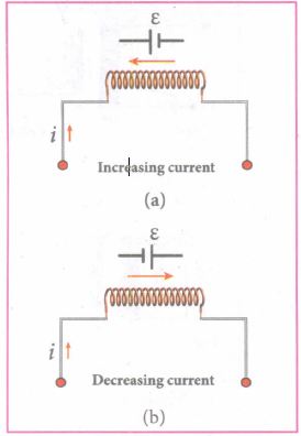
The inductance plays the same role in a circuit as mass and moment of inertia play at a mechanical motion. When a circuit is switched on, the increasing current induces an emf which opposes the growth of current in a circuit (Figure (a)). Likewise, when circuit is broken, the decreasing current induces an emf in the reverse direction. This emf now opposes the decay of current (Figure (b)).
Thus, the inductance of the coil opposes any change in current and tries to maintain the original state
19.
A = 70 x 10-4m2; N = 600 turns
B = 0.4 Wbm-2; f = 500 rpm
The instantaneous emf is
ε = εmsinωt
since \({ \epsilon }_{ m }=N{ \Phi }_{ m }\omega =N(BA)(2\pi f)\)
ε = NBA x 2\(\pi\)f x sinωt
(i) When ωt = 0o,
ε = εm sin0 = 0
(ii) When ωt = 90o,
ε = εmsin90o = NBA x 2\(\pi\)f x 1
= 600 x 0.4 x 70 x 10-4 x 2 x \(\frac{22}{7}\times(\frac{500}{60})\)
= 88V
(iii) When ωt = 90° – 60° = 30°,
ε = εm sin30o = 88 x \(\frac{1}{2}\) = 44V
20.
21.
(d)
current lags voltage by π/2
22.
(d)
changes both current and voltage
23.
(b)
permanent magnets
24.
(b)
self - induction
25.
(a)
Foucault
26.
(b)
very large
27.
(a)
mutual induction
28.
(a)
directly proportional to N
29.
(b)
magnetic field
30.
(a)
0.3 H
31.
\(Q_{midpoint}=\frac{Q}{\sqrt{1^2+1^2}}=\frac{Q}{\sqrt2}\)
32.
\(\omega=250 \mathrm{rad} / \mathrm{s}, C=4 \times 10^{-} \mathrm{F} \)
\(R=100 \Omega, \quad \mathrm{V}_{\mathrm{R}}=40 \mathrm{~V} \)
\(\therefore I_{\mathrm{R}}=\frac{V_R}{100}=\frac{40}{100}=0.4 \mathrm{~A} \)
\(\omega=\frac{1}{\sqrt{L C}} \)
\(\omega^2=\frac{1}{L C} \)
\((250)^2=\frac{1}{L \times 4 \times 10^{-6}} \)
\(L=\frac{1}{4 \times(250)^2 \times 10^{-6}} \)
\(=\frac{1}{4 \times 250 \times 250 \times 10^{-6}} \)
\(=\frac{1}{1000 \times 10^{-6} \times 250} \)
\(=\frac{10^3}{250}=\frac{1000}{250}=4 \mathrm{H}\)
Voltage acnoss L, Vt = IXL
VL = l x L x ω
= 0.4 x 4 x 250
0.4 x 1000 = 400 V
33.
(a)
34.
\(A_1 =4 \times 10^{-4} \mathrm{~m}^2 \)
\(N_1 =10 \text { turns } \)
\(A_2 =4 \times 10^{-4} \mathrm{~m}^2 \)
\(N_2 =15 \times 10^{-}=1500 \mathrm{turn} / \mathrm{m} \)
\(\phi =B_2 A_2=\left(\mu_0 \mathrm{n}_2 I_2\right) \mathrm{A}_1 \)
\(Where, \mathrm{n}_2=\frac{\mathrm{N}_2}{l}=1500 \mathrm{turn} / \mathrm{m}\)
The mutual Inductance is,
\(M =\frac{N_1 o_{12}}{I_2}=\mu_0 n_2 N_1 A_1 \)
\(=4 \pi \times 10^{-7} \times 1500 \times 10 \times 4 \times 10^{-4} \)
\(=7.54 \times 10^{-6} \mathrm{H}=7.54 \mu \mathrm{H}\)
35.
\(\text {emf } e=8 \mathrm{~V} \)
\(d I=I_1-I_0=2-(-2)=4 \mathrm{~A} \)
\(\text {dt }=0.05 \mathrm{~s} \)
\(L=\frac{-e}{d I / d t}=\frac{-8}{4 / 0.05} \)
\(=\frac{-8 \times 0.05}{4}=\frac{-0.40}{4} \)
=-0.1 H
-ve sign indicates that self-induced emf always opposes the current w.r.t. time.
36.
Given: N = 1000
A = 100 cm2 = 10-2 m2
v = 100 rpm = \(\frac{100}{60}\) rps
B = 3.6 x 10⁻²⁷
em = ?
em = NBAω = NBA (2πγ)
= 1000 x 3.6 x 10-2 x 10-2 x 2 x \(\frac{22}{7}\times\frac{100}{60}\)
e = 5.77 V
37.
I = 40cm = 0.4m
A = 20 cm2 = 20 x 10-4 m2
N = 800, L =?
\(L=\frac { { \mu }_{ o }{ N }^{ 2 }{ A } }{ l } \) = \(\frac { 4\pi \times 3\times { 10 }^{ -7 }\times { \left( 800 \right) }^{ 2 }\times 20\times { 10 }^{ -4 } }{ 0.4 } \)
L = 4.02 x 10⁻²H
38.
Given:
We know that e = -\(\frac { d\Phi }{ dt } \)
e = \(\frac{d}{dt}\) (5t3 + 4t2 + 2t)
e = 15t2 + 8t + 2
for t = 2s, e = 15 x (2)2 + 8 (2) + 2
e = 78V
39.
Given:
B = 10T, N = 50 turns
A = 100 cm2 = 10-2m2
dt = 0.15S
Magnetic flux linked with the coil initially,
Φ1 = NBA = 50 x 10 x 10-2= 5wb
But magnetic flux linked with the coil finally, i.e (when removed from 'B')
Φ2 = 0
Formula:
∴ emf induced, e = - \(\frac { d\phi }{ dt } \)
= - \(\frac { { (\phi }_{ 2 }-{ \phi }_{ 1 }) }{ dt } =-\frac { (0-5) }{ 0.15 } \)
e = 33.33V
40.
(i) Power of a circuit is defined as the rate of consumption of electric energy in that circuit. It is given by the product of the voltage and current.
In an AC circuit, the voltage and current vary continuously with time. Let us first calculate the power at an instant and then it is averaged over a complete cycle.
(ii) The alternating voltage and alternating current in the series inductive RLC circuit at an instant are given by
v=Vm sinωt and i=Im=(ωωt+\(\phi \))t+\(\phi \))
(iii) where \(\phi \) is the phase angle between v and i. The instantaneous power is then written as
P=vi =VmIm sinωt sin(ωt + \(\phi \))
=VmIm sinωt [sin ωt cos\(\phi \) - cosωt sin\(\phi \)]
P=VmIm [cos\(\phi \) sin2ωt - sinωt cosωt sin\(\phi \)] ....(1)
(iv) Here the average of sin2ωt over a cycle is\(\frac{1}{2}\)and that of sin ωt cos ωt is zero. Substituting these values, we obtain average power over a cycle.
Pav =VmIm cos\(\phi \) x \(\frac { 1 }{ 2 } \)
=\(\frac { { V }_{ m } }{ \sqrt { 2 } } \frac { { I }_{ m } }{ \sqrt { 2 } } cos\phi\)
Pav = VRMS IRMS cos\(\phi \) ....(2)
(v) where VRMS IRMS is called apparent power and cos\(\phi \) is power factor. The average power of an AC circuit is also known as the true power of the circuit.
Special Cases:
(i) For a purely resistive circuit, the phase angle between voltage and current is zero and cos\(\phi \)=1
∴ Pav =VRMS IRMS
(ii) For a purely inductive or capacitive circuit, the phase angle is ± \(\frac { \pi }{ 2 } \) and cos\(\left( \pm \frac { \pi }{ 2 } \right) \)=0
∴ Pav =0
(iii) For series RLC circuit, the phase angle
\(\phi \) =tan-1\(\left( \frac { { X }_{ L }-{ X }_{ C } }{ R } \right) \)
∴ Pav =VRMS IRMS cos\(\phi \)
(iv) For series RLC circuit at resonance, the phase angle is zero and cos\(\phi \)=1
∴ Pav =VRMS IRMS
41.
(i) Consider a rectangular coil of turns kept in a uniform magnetic field \(\vec{B}\) as shown in Figure (a). The coil rotates in anti-clockwise direction with an angular velocity ω about an axis, perpendicular to the field, and to the plane of the paper.
(ii) At time = 0, the plane of the coil is perpendicular to the field and the flux linked with the coil has its maximum value \({ \Phi }_{ m }=BA\) (where A is the area of the coil).
(iii) In a time t seconds, the coil is rotated through an angle θ (= ωt) in anti-clockwise direction. In this position, the flux linked is NBA cos ωt, is due to the component of B normal to the plane of the coil (Figure(b)). The component parallel to the plane (B sin ωt) has no role in electromagnetic induction. Therefore, the flux linkage with the coil at this deflected position is
NΦB = NBA cosθ = NBA cos ωt
According to Faraday's law, the emf induced at that instant is
.JPG)
\(ε=- \frac { d }{ dt } (N{ \Phi }_{ B })=-\frac { d }{ dt } (NBAcos\omega t)\)
= -NBA (-sin ωt)ω
= NBAω sin ωt
(iv) When the coil is rotated through 900 from initial position, sin ωt = 1. Then the maximum value of induced emf is
εm = NBAω
Therefore, the value of induced emf at that instant is then given by,
ε = εm sinωt ....(1)
.JPG)
(vii) It is seen that the induced emf varies as sine function of the time angle ωt. The graph between induced emf and time angle for one rotation of coil will be a sine curve (Figure) and the emf varying in this manner is called sinusoidal emf or alternating emf.
If this alternating voltage is given to a closed circuit, a sinusoidally varying current flows in it. This current is called alternating current and is given by,
i = Im sinωt ....(2)
Where, Im is the maximum value of induced current.
42.
(a) Induction stove
(i) Induction stove is used to cook the food quickly and safely with less energy consumption. Below the cooking zone, there is a tightly wound coil of insulated wire.
(ii) The cooking pan made of suitable material, is placed over the cooking zone. When the stove is switched on, an alternating current flowing in the coil produces high frequency alternating magnetic field which induces very strong eddy currents in the cooking pan.
(iii) The eddy currents in the pan produce so much of heat due to Joule heating which is used to cook the food.
(b) Eddy current brake
(i) This eddy current braking system is generally used in high speed trains and roller coasters. Strong electromagnets are fixed just above the rails.
(ii) To stop the train, electromagnets are switched on. The magnetic field of these magnets induces eddy currents in the rails which oppose or resist the movement of the train. This is Eddy current linear brake.
(c) Eddy current testing
(i) It is one of the simple non-destructive testing methods to find defects like surface cracks, air bubbles present in a specimen.
(ii) A coil of insulated wire is given an alternating electric current, so that it produces an alternating magnetic field.
(iii) When this coil is brought near the test surface, eddy current is induced in the test surface.
(iv) The presence of defects causes the change in phase and amplitude of the eddy current that can be detected by some other means. In this way, the defects present in the specimen are identified.
(d) Electro magnetic damping:
(i) The armature of the galvanometer coil is wound on a soft iron cylinder.
(ii) Once the armature is deflected, the relative motion between the soft iron cylinder and the radial magnetic field induces eddy current in the cylinder.
(iii) The damping force due to the flow of eddy current brings the armature to rest immediately and then galvanometer shows a steady deflection. This is called electromagnetic damping.
43.
(i) Consider a closed circuit consisting of a coil C of insulated wire and a galvanometer G. The galvanometer does not indicate deflection as there is no electric current in the circuit.
(ii) When a bar magnet is inserted into the stationary coil, with its north pole facing the coil, there is a momentary deflection in the galvanometer. This indicates that an electric current is set up in the coil. If the magnet is kept stationary inside the coil, the galvanometer does not indicate deflection.
(iii) The bar magnet is now withdrawn from the coil, the galvanometer again gives a momentary deflection but in the opposite direction. So, the electric current flows in opposite direction. Now if the magnet is moved faster, it gives a larger deflection due to a greater current in the circuit.
(iv) The ar magnet is reversed, i.e., the south pole now faces the coil. When the above experiment is repeated, the deflections are opposite to that obtained in the case of north pole.
(v) If the magnet is kept stationary and the coil is moved towards or away from the coil, similar results are obtained. It is concluded that whenever there is a relative motion between the coil and the magnet, there is deflection in the galvanometer, indicating the electric current setup in the coil.

12th Standard Syllabus & Materials
12th Standard
TN 12th Computer Applications களப்பெயர் முறைமை (DNS) Sample Question Papers Study Material - QB365 Set A
NEW12th Standard
TN 12th Computer Applications வலையமைப்பு எடுத்துக்காட்டுகள் மற்றும் நெறிமுறைகள் Sample Question Papers Study Material - QB365 Set A
NEW12th Standard
TN 12th Computer Applications கணினி வலையமைப்பு ஓர் அறிமுகம் Sample Question Papers Study Material - QB365 Set A
NEW12th Standard
TN 12th Computer Applications PHP-உடன் MySQL-ஐ இணைத்தல் Sample Question Papers Study Material - QB365 Set A



Tamilnadu Stateboard 12th Standard Subjects

Maths

Chemistry
Physics

Biology

Computer Science

Business Maths and Statistics

Economics

Commerce

Accountancy

History

Computer Applications
Biology
Computer Technology
Computer Applications
Computer Science
Business Maths and Statistics
Commerce
Economics
Maths
Chemistry
Physics
Computer Technology
History
Accountancy

Tamil

English

French
Tamilnadu Stateboard Standards

