
 100% FREE ACCESS
12th Standard Syllabus & Materials
12th Standard
TN 12th Computer Applications மின்னணு தரவு பரிமாற்றம் Sample Question Papers Study Material - QB365 Set A
NEW12th Standard
TN 12th Computer Applications மின் - வணிக பாதுகாப்பு அமைப்புகள் Sample Question Papers Study Material - QB365 Set A
NEW12th Standard
TN 12th Computer Applications மின்னணு செலுத்தல் முறைகள் Sample Question Papers Study Material - QB365 Set A
NEW12th Standard
TN 12th Computer Applications மின் - வணிகம் Sample Question Papers Study Material - QB365 Set A
NEW12th Standard
TN 12th Computer Applications திறந்த மூல கருத்துருக்கள் Sample Question Papers Study Material - QB365 Set A
NEW12th Standard
TN 12th Computer Applications வலையமைப்பு வடமிடல் Sample Question Papers Study Material - QB365 Set A

Published on: 02/09/2020
12th Standard Physics English Medium Important 3 Mark Book Back Questions (New Syllabus) 2020
Download Tamil Nadu 12th Standard Physics question papers, model tests, one-mark questions, important questions, and public exam papers in PDF format. Free study materials and answer keys for TN State Board students.
Questions + Answers key
Take MCQ Physics Test1.
In a transistor connected in the common base configuration, \(\alpha\) = 0 95, IE = 1 mA. Calculate the values of IC and IB.
2.
Find the dispersive power of a prism if the refractive indices of flint glass for red, green and violet colours are 1.613, 1.620 and 1.632 respectively.
3.
If the focal length is 150 cm for a lens, what is the power of the lens?
4.
Light travelling through transparent oil enters in to glass of refractive index 1.5. If the refractive index of glass with respect to the oil is 1.25, what is the refractive index of the oil?
5.
Calculate the average atomic mass of chlorine if no distinction is made between its different isotopes?
6.
The relative magnetic permeability of the medium is 2.5 and the relative electrical permittivity of the medium is 2.25. Compute the refractive index of the medium.
7.
The self-inductance of an air-core solenoid is 4.8 mH. If its core is replaced by iron core, then its self-inductance becomes 1.8 H. Find out the relative permeability of iron.
8.
A closed coil of 40 turns and of area 200 cm2, is rotated in a magnetic field of flux density 2 Wb m–2. It rotates from a position where its plane makes an angle of 30o with the field to a position perpendicular to the field in a time 0.2 s. Find the magnitude of the emf induced in the coil due to its rotation.
9.
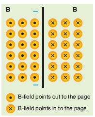
The magnetic field shown in the figure is due to the current carrying wire. In which direction does the current flow in the wire?
10.
Let the magnetic moment of a bar magnet be \(\overset { \rightarrow }{ { p }_{ m } } \) whose magnetic length is d = 2l and pole strength is qm. Compute the magnetic moment of the bar magnet when it is cut into two pieces
(a) along its length
(b) perpendicular to its length.
11.
Resistance of a material at 20oC and 40oC are 45 Ω and 85 Ω respectively. Find its temperature coefficient of resistivity.
12.
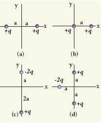
Calculate the electric dipole moment for the following charge configurations.
13.
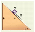
A block of mass m carrying a positive charge q is placed on an insulated frictionless inclined plane as shown in the figure. A uniform electric field E is applied parallel to the inclined surface such that the block is at rest. Calculate the magnitude of the electric field E.
14.
Determine the number of electrons flowing per second through a conductor, when a current of 32 A flows through it.
15.
Calculate the number of electrons in one coulomb of negative charge.
16.
Light of wavelength 390 nm is directed at a metal electrode. To find the energy of electrons ejected, an opposing potential difference is established between it and another electrode. The current of photoelectrons from one to the other is stopped completely when the potential difference is 1.10 V. Determine i) the work function of the metal and ii) the maximum wavelength of light that can eject electrons from this metal.
17.
Derive an expression for de Broglie wavelength of electrons.
18.
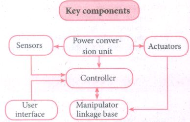
Discuss the functions of key components in Robots?
19.
The thickness of a glass slab is 0.25 m. It has a refractive index of 1.5. A ray of light is incident on the surface of the slab at an angle of 60o. Find the lateral displacement of the light when it emerges from the other side of the glass slab.
20.
Write a note on photodiode.
21.
Explain in detail the four fundamental forces in nature.
22.
Discuss the gamma emission process with example.
23.
Obtain the expression for energy stored in the parallel plate capacitor.
24.
Derive an expression for the torque experienced by a dipole due to a uniform electric field.
25.
A conducting rod of length 0.5 m falls freely from the top of a building of height 7.2 m at a place in Chennai where the horizontal component of Earth’s magnetic field is 4.04 × 10⁻⁵ T. If the length of the rod is perpendicular to Earth’s horizontal magnetic field, find the emf induced across the conductor when the rod is about to touch the ground. (Assume that the rod falls down with constant acceleration of 10 m s–2)
26.
Show the time period of oscillation when a bar magnet is kept in a uniform magnetic field is \(T=2\pi \sqrt { \frac { 1 }{ { p }_{ m }B } } \) in second, where I represents a moment of inertia of the bar magnet, pm is the magnetic moment and B is the magnetic field.
27.
Explain how frequency of incident light varies with stopping potential.
28.
State and prove De Morgan’s first and second theorem.
29.
Explain the experimental determination of refractive index of the material of the prism using spectrometer.
30.
Explain the Young’s double slit experimental setup and obtain the equation for path difference.
31.
Explain the basic elements of communication system with the necessary block diagram.
32.
Derive the equation for acceptance angle and numerical aperture of optical fibre.
33.
What is tangent law? Discuss in detail.
34.
Obtain a relation for the magnetic field at a point along the axis of a circular coil carrying current using Biot-Savart law.
35.
Prove that the total energy is conserved during LC oscillations.
36.
How are the three different emfs generated in a three-phase AC generator? Show the graphical representation of these three emfs.
37.
Using Faraday’s law of electromagnetic induction, derive an equation for motional emf.
38.
1.
α = \(\frac{I_C}{I_E}\)
IC = α IE = 0.95 x 1 = 0.95 mA
IE = IB + IC
∴ IB = IE - IC = 1 - 0.95 = 0.05 mA
2.
Given, nv = 1.632; nR = 1.613; nG = 1.620
Equation for dispersive power is,
\(\omega =\cfrac { \left( { n }_{ v }-{ n }_{ g } \right) }{ \left( { n }_{ G }-1 \right) } \)
Substituting the values,
\(\omega =\cfrac { 1.632-1.613 }{ 1.620-1 } =\cfrac { 0.019 }{ 0.620 } =0.0306\)
The dispersive power of the prism is,\(\\ \omega =0.0306\)
3.
Given, focal length, f = 150 cm = 1.5 m
Equation for power of lens is, \(p=\cfrac { 1 }{ f } \)
Substituting the values,
\(p=\cfrac { 1 }{ 1.5 } =0.67 D\)
As the power is positive, it is a converging lens.
4.
Given, ngo = 1.25 and ng = 1.5
Refractive index of glass with respect to oil,
\({ n }_{ go }=\cfrac { { n }_{ g } }{ { n }_{ 0 } } \)
Rewriting for refractive index of oil,
\({ n }_{ p }=\cfrac { { n }_{ g } }{ { n }_{ go } } =\cfrac { 1.5 }{ 1.25 } =1.2\)
The refractive index of oil is, no = 1.2
5.
The element chlorine is a mixture of 75.77% of \(_{ 17 }^{ 35 }{ Cl }\) and 24.23% of \(_{ 17 }^{ 37 }{ Cl }\). So the average atomic mass will be
\(\frac { 75.77 }{ 100 } \times 34.96885u+\frac { 24.23 }{ 100 } \times 36.96593u\)
= 35.453 u
In fact, the chemist uses the average atomic mass or simply called chemical atomic weight (35.453 u for chlorine) of an element. So it must be remembered that the atomic mass which is mentioned in the periodic table is basically averaged atomic mass.
6.
Dielectric constant (relative permittivity of the medium) is εr = 2.25
Magnetic permeability is μr = 2.5
Refractive index of the medium,
n = \(\sqrt { { \varepsilon }_{ r }{ \mu }_{ r } } =\sqrt { 2.25\times 2.5 } \) = 2.37
7.
Lair = 4.8 x 10⁻³H
Liron = 1.8H
Lair = \(\mu_{o}\)n2Al = 4.8 x 10⁻³H
Liron = \(\mu_{o}\)n2Al = \(\mu_{o}\mu_r\)n2Al = 1.8H
\(\therefore { \mu }_{ r }=\frac { { L }_{ iron } }{ { L }_{ air } } =\frac { 1.8 }{ 4.8\times { 10 }^{ -3 } } =375\)
8.
N = 40 turns; B = 2 Wb m-2
A = 200 cm2 = 200 x 10-4 m2;
Initial flux, \(\Phi_i\) = BA cos\(\theta\)
= 2 x 200 x 10-4 x cos60o
since θ = 90°− 30°= 60°
\(\Phi_i\)= 2 x 10⁻² Wb
Final flux, \(\Phi_f\) = BA cos\(\theta\)
= 2 x 200 x 10-4 x cos0o since \(\theta\) = 0o
\(\Phi_f\) = 4 x 10⁻²Wb
Magnitude of the induced emf is
\(ε =N\frac { d{ \Phi }_{ B } }{ dt } \)
\(=\frac { 40\times (4\times { 10 }^{ -2 }-2\times { 10 }^{ -2 }) }{ 0.2 } =4V\)
9.
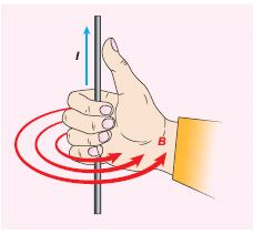
Using right hand rule, current flows upwards.
10.
(a) a bar magnet cut into two pieces along its length:
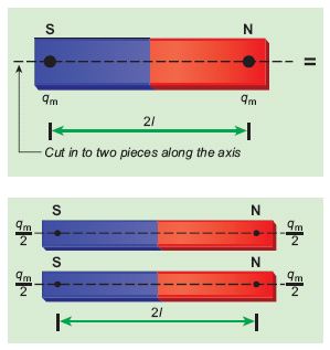
When the bar magnet is cut along the axis into two pieces, new magnetic pole strength is \({ q }_{ m }^{ ' }=\frac { { q }_{ m } }{ 2 } \) but magnetic length does not change. So, the magnetic moment is
\({ p }_{ m }^{ ' }={ q' }_{ m }2l\)
\({ p }_{ m }^{ ' }=\frac { { q }_{ m } }{ 2 } 2l=\frac { 1 }{ 2 } ({ q }_{ m }2l)=\frac { 1 }{ 2 }p_ m\)
In vector notation, \(\vec{p}'_m=\frac{1}{2}\vec{p}_m\)
(b) a bar magnet cut into two pieces perpendicular to the axis:
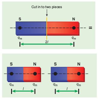
When the bar magnet is cut perpendicular to the axis into two pieces, magnetic pole strength will not change but magnetic length will be halved. So the magnetic moment is
\({ p }_{ m }^{ ' }={ q }_{ m }\times \frac { 1 }{ 2 } (2l)=\frac { 1 }{ 2 } ({ q }_{ m }.2l)=\frac { 1 }{ 2 } { p }_{ m }\)
In vector notation, \(\vec{p}'_m=\frac{1}{2}\vec{p}_m\)
11.
T0 = 20oC, T = 40oC, Ro = 45 Ω , R = 85 Ω
\(\alpha =\frac { 1 }{ { R }_{ 0 } } \frac { \Delta R }{ \Delta T } \)
\(\alpha=\frac{1}{45}\left(\frac{85-45}{40-20}\right)=\frac{1}{45}(2)\)
\(\alpha=0.044 \text { per }^{\circ} C\)
12.
Case (a) The position vector for the +q on the positive x-axis is a\(\hat { i } \) and position vector for the +q charge the negative x-axis is - a\(\hat { i } \) So the dipole moment is,
\( \vec { p } =(+q)(a\hat { i } )+(+q)(-a\hat { i } )=0\)
Case (b) In this case one charge is placed at the origin, so its position vector is zero. Hence only the second charge +q with position vector a\(\hat { i } \) contributes to the dipole moment, which is \(\vec { p } =qa\hat { i } \).
From both cases (a) and (b), we can infer that in general the electric dipole moment depends on the choice of the origin and charge configuration. But for one special case, the electric dipole moment is independent of the origin. If the total charge is zero, then the electric dipole moment will be the same irrespective of the choice of the origin. It is because of this reason that the electric dipole moment of an electric dipole (total charge is zero) is always directed from –q to +q, independent of the choice of the origin.
Case (c) \(\vec { p } =(-2q)a\hat { j } +q(2a)(-\hat { j } )=-4qa\hat { j } \)
Note that in this case \(\vec { p } \) is directed from -2q to +q.
Case (d) \(\vec { p } =-2qa(-\hat { i } )+qa\hat { j } +qa(-\hat { j } )\)
= \(2qa\hat { i } \).
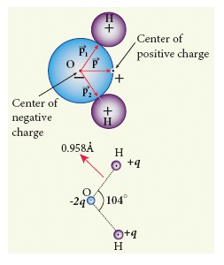
The water molecule (H2O) has this charge configuration. The water molecule has three atoms (two H atom and one O atom). The centers of positive (H) and negative (O) charges of a water molecule lie at different points, hence it possess permanent dipole moment. The electric dipole moment \(\vec { p } \) is directed from center of negative charge to the center of positive charge, as shown in the figure.
13.
Note: A similar problem is solved in XIth Physics volume I, unit 3 section 3.3.2. There are three forces that acts on the mass m:
(i) The downward gravitational force exerted by the Earth (mg)
(ii) The normal force exerted by the inclined surface (N)
(iii) The Coulomb force given by uniform electric field (qE) The free body diagram for the mass m is drawn below.
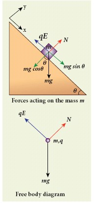
A convenient inertial coordinate system is located in the inclined surface as shown in the figure. The mass m has zero net acceleration both in x and y-direction.
Along x-direction, applying Newton’s second law, we have
mg sinθ\(\hat { i } \) - qE\(\hat { i } \) = 0
mg sinθ - q E = 0
or, E = \(\\ \frac { mgsin\theta }{ q } \)
Note that the magnitude of the electric field is directly proportional to the mass m and inversely proportional to the charge q. It implies that, if the mass is increased by keeping the charge constant, then a strong electric field is required to stop the object from sliding. If the charge is increased by keeping the mass constant, then a weak electric field is sufficient to stop the mass from sliding down the plane.
The electric field also can be expressed in terms of height and the length of the inclined surface of the plane.
E = \(\frac { mgh }{ qL } \).
14.
I = 32 A , t = 1 s
Charge of an electron, e = 1.6 x 10⁻¹⁹ C
The number of electrons flowing per second, n = ?
\(I=\frac { q }{ t } =\frac { ne }{ t } \)
\(n=\frac { It }{ e } \)
\(n=\frac { 32\times 1 }{ 1.6\times { 10 }^{ -19 }C } \)
n = 20 x 1019 = 2 x 10²⁰ electrons
15.
According to the quantisation of charge
q = ne
Here q = 1C. So the number of electrons in 1 coulomb of charge is
n = \(\frac { q }{ e } =\frac { 1C }{ 1.6\times 10^{ -19 } } \) = 6.25 x 10¹⁸ electrons
16.
i) The work function is given by
ϕ0 = hv - Kmax = \(\frac { hc }{ \lambda } \) - eV0
since Kmax = eV0
\(=\left[ \frac { 6.626\times { 10 }^{ -34 }\times 3\times { 10 }^{ 8 } }{ 390\times 10^{ -9 } } \right] \) - [1.6 x 10-19 x 1.10]
= 5.10 x 10⁻¹⁹ - 1.76 x 10-19 = 3.34 x 10⁻¹⁹ J
= 2.09 eV
ii) The threshold wavelength is
\(\lambda_{0}=\frac{h c}{\phi_o}=\frac{6.626 \times 10^{-34} \times 3 \times 10^{8}}{3.34 \times 10^{-19}}\)
= 5.951 x 10⁻⁷ m = 5951 \(\mathring { A }\).
17.
(i) An electron of mass m is accelerated through a potential difference of V volt. The kinetic energy acquired by the electron is given by
\(\cfrac { 1 }{ 2 } { mv }^{ 2 }=ev\)
(ii) Therefore, the speed v of the electron is
\(v=\sqrt { \cfrac { 2ev }{ m } } \)
Hence, the de Broglie wavelength of the matter waves associated with electron is
\(\lambda =\cfrac { h }{ mv } =\cfrac { h }{ \sqrt { 2mev } } \)
(iii) Substituting the known values in the above equation, we get
\(\lambda =\cfrac { 6.26\times { 10 }^{ -34 } }{ \sqrt { 2V\times 1.6\times { 10 }^{ -19 }\times 9.11\times { 10 }^{ -31 } } } \)
= \(\cfrac { 12.27\times { 10 }^{ -10 } }{ \sqrt { V } } m\)
\(\lambda =\cfrac { 12.27 }{ \sqrt { V } } \overset { o }{ A } \)
(iv) Since the kinetic energy of the electron, K = eV, then the de Broglie wavelength associated with electron can be also written as
\(\lambda =\cfrac { h }{ \sqrt { 2mK } } \)
18.
The key components in Robots are power conversion unit, actuators, controller, sensors, manipulators and necessary software.
The following diagram clearly explains the functions of the key components.
Most Robots are composed of 3 Main parts:
i) The controller:
It is known as the 'brain' which is run by computer program. It gives commands for the moving parts to perform the job.
ii) Sensors:
It tells the robot about its surroundings. It helps to determine the sizes and shapes of the objects around, distance between the objects and directions as well.
iii) Mechanical parts:
It makes the robot to move, grab, turn and lift. It consists of motors, pistons, grippers, wheels and gears.
19.
Given, thickness of the slab, t = 0.25 m, refractive index, n = 1.5, angle of incidence, i = 60o.
Using Snell’s law, 1 sin i = n sin r
\(sinr=\cfrac { sini }{ n } =\cfrac { sin60^o }{ 1.5 } =0.58\)
\(r={ sin }^{ -1 }(0.58)=35.25^{ 0 }=35^o15'0''\)
Lateral displacement is, \(L=t\left( \cfrac { sin\left( i-r \right) }{ cos\left( r \right) } \right) \)
\(L=\left( 0.25 \right) \times \left( \cfrac { sin\left( 60-35.25 \right) }{ cos\left( 35.25 \right) } \right) =0.1281m\)
The lateral displacement is, L = 12.81 cm
20.
Photo diode:
A p -n junction diode which converts an optical signal into electrical current is known as photodiode.
(i) The operation of photodiode is exactly inverse to that of an LED. Photodiode works in reverse bias condition.
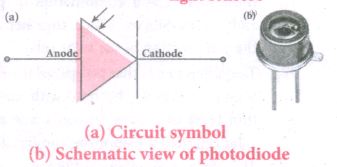
(ii) The direction of arrows indicates that the light is incident on the photo diode.
(iii) The device consists of a p-n junction semiconductor made of photosensitive material kept safely inside a plastic case as shown in fig.
(iv) It has a small transparent window that allows light to be incident on the p-n junction.
(v) Photodiodes car generate current when the p - n junction is exposed to light and hence are called as light sensors.
(vi) When a photon of sufficient energy (hv) strikes the depletion region of the diode, some of the valence band electron are elevated into conduction band, in turn holes are developed in the valence band. This creates electron-hole pairs. The amount of electron - hole pairs generated depends on the intensity of light incident on the p - n junction.
(vii) These electron and holes are swept across the p-n junction by the electric field created by reverse voltage before recombination takes place. Thus, holes move towards the n - side and electrons towards the P - side - when the external circuit is made, the electrons flow through the external circuit and constitute the photo current.
(viii) When the incident light is zero, there exists a reverse current which is negligible. This reverse current in the absence of any. incident light is called dark current and is. due to the thermally generated minority carriers.
21.
Fundamental forces of nature:
(i) It is known that there exists gravitational force between two masses and it is universal in nature. Our planets are bound to the Sun through gravitational force of the Sun.
(ii) ''Force is the external agency applied on a body to change its state of rest and motion"
There are four basic forces in nature.
(a) Gravitational force
(b) Electromagnetic force
(c) Strong nuclear force
(d) Weak nuclear force.
(a) Gravitational force :
(i) It is the force between any two objects in the universe.
(ii) It is an attractive force by virtue of their masses
(iii) By Newton's law of gravitation, the gravitational force is directly proportional to the product of the masses and inversely proportional to the square of the distance between them.
(iv) Gravitational force is the weakest force among the fundamental forces of nature but has the greatest large-scale impact on the universe.
(v) Unlike the other forces, gravity works universally on all matter and energy, and is universally attractive.
(b) Electromagnetic force :
(i) It is the force between charged particles or the force between two current carrying wires.
(ii) It is attractive for unlike charges and repulsive for like charges.
(iii) The electromagnetic force obeys inverse square law.
(iv) It is very strong compared to the gravitational force.
(v) It is the combination of electrostatic and magnetic forces.
(c) Strong nuclear force :
(i) It is the strongest of all the basic forces of nature.
(ii) It, however, has the shortest range, of the order of 10-15 m.
(iii) This force holds the protons and neutrons together in the nucleus of an atom.
(d) Weak nuclear force :
(i) Weak nuclear force is even shorter in range than nuclear force.
(ii) This force plays an important role in beta decay and energy production of stars
(iii) During the fusion of hydrogen into helium in sun, neutrinos and enormous radiations are produced through weak force.
(iv) In our day to - day life, we require these four fundamental forces.
To put it in simple words :
(a) we are in the Earth because of Earth's gravitational attraction on our body.
(b) We are standing on the surface of the earth because of the electromagnetic force between atoms of the surface of the earth with atoms in our foot.
(c) The atoms in our body are stable because of strong nuclear force.
(d) Finally, the lives of species in the earth depend on the solar energy from the sun and it is due to weak force which plays vital role during nuclear fusion reactions going on in the core of the sun.
22.
(i) In \(\alpha \text { and } \beta \) decay, most of the daughter nucleus is in the excited state.
(ii) The life time of excited state is approximately 10-11 s.
(iii) This excited state nucleus immediately returns to the ground state or lower energy state by emitting highly energetic photons called rays of energy in order of MeV.
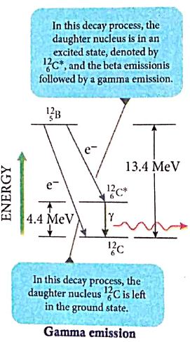
The gamma decay is given by,
\({ }_{\mathrm{Z}}^{\mathrm{A}} \mathrm{X}^{*} \rightarrow{ }_{\mathrm{Z}}^{\mathrm{A}} \mathrm{X}+\gamma-\text { ray }\)
(iv) Here the asterisk(*) means excited state nucleus.
(a) In gamma decay, there is no change in the mass number or atomic number of the nucleus. when \({ }_{5}^{12} \mathrm{~B}\) undergoes beta decay directly into ground state carbon (\(_{ 6 }^{ 12 }{ C})\) by emitting an electron of maximum of energy 13.4 MeV.
(b) If \({ }_{5}^{12} \mathrm{~B}\) undergoes beta decay to an excited state of carbon \(({ _{ 6 }^{ 12 }{ C } }^{ * })\) by emitting an electron of maximum energy 9.0 MeV followed by gamma decay to ground state by emitting a photon of energy 4.4 MeV. It is represented by,
\(_{ 5 }^{ 12 }{ B }\rightarrow _{ 6 }^{ 12 }{ C+ }{ e }^{ - }+\overline { v } \)
\(_{ 6 }^{ 12 }{ C^* }\rightarrow _{ 6 }^{ 12 }{ C }+\gamma -rays\)
23.
Energy stored in the capacitor
i) Capacitor not only stores the charge but also it stores energy. When a battery is connected to the capacitor, electrons of total charge - Q are transferred from one plate to the other plate. To transfer the charge, work is done by the battery. This work done is stored as electrostatic potential energy in the capacitor.
ii) To transfer an infinitesimal charge dQ for a potential difference V, the work done is given by
dW = V dQ
Where \(V=\frac { Q }{ C } \) .....(1)
iii) The total work done to charge a capacitor is
\(W=\int _{ 0 }^{ Q }{ \frac { Q }{ C } } dQ=\frac { { Q }^{ 2 } }{ 2C } \quad \quad ....(2)\)
This work done is stored as electrostatic potential energy (UE) in the capacitor.
\({ U }_{ E }=\frac { { Q }^{ 2 } }{ 2C } =\frac { 1 }{ 2 } { CV }^{ 2 },\quad (\therefore Q=CV)\quad ....(3)\)
(iv) This stored energy is thus directly proportional to the capacitance of the capacitor and the square of the voltage between the plates of the capacitor.Substituting \(C=\frac { { \varepsilon }_{ 0 }A }{ d } \) and V = Ed.
\(U=\frac { 1 }{ 2 } \left( \frac { { \varepsilon }_{ 0 }A }{ d } \right) { (Ed) }^{ 2 }=\frac { 1 }{ 2 } { \varepsilon }_{ 0 }(Ad){ E }^{ 2 }\quad \quad \quad \quad \quad ...(4)\)
where Ad = volume of the space between the capacitor plates. The energy stored per unit volume of space is defined as energy density \({ u }_{ E }=\frac { U }{ Volume } \)
Equation (4) ⇒ \({ u }_{ E }=\frac{1}{2}{ \varepsilon }_{ 0 }{ E }^{ 2 }\).....(5)
(v) From equation (5),
(a) We infer that the energy is stored in the electric field existing between the plates of the capacitor. Once the capacitor is allowed to discharge, the energy is retrieved.
(b) The energy density depends only on the electric field and not on the size of the plates of the capacitor.
(c) This is true for the electric field due to any type of charge configuration.
24.
Torque experienced by an electric dipole in the uniform electric field:
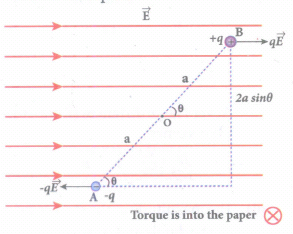
Consider an electric dipole of dipole moment \(\vec { p } \) placed in a uniform electric field \(\vec { E } \) whose field lines are equally spaced and point in the same direction. The charge +q will experience a force \(q\vec { E } \) in the direction of the field and charge -q will experience a force \(-q\vec { E } \) in a direction opposite to the field. Since the external field \(\vec { E } \) is uniform, the total force acting on the dipole is zero. These two forces acting at different points will constitute a couple and the dipole experience a torque. This torque tends to rotate the dipole.
The total torque on the dipole about the point O
\(\vec{\tau}=\overrightarrow{O A} \times(-q \vec{E})+\overrightarrow{O B} \times q \vec{E}\) ......(1)
Using right-hand corkscrew rule, it is found that total torque is perpendicular to the plane of the paper and is directed into it.
The magnitude of the total torque
\(\tau =|\vec { OA } |\left( -q\vec { E } \right) |sin\theta +|\vec { OB } ||\vec { E } |sin\theta \)
\(\tau =qE.2a\quad sin\theta \) ....(2)
where θ is the angle made by \(\vec { p } \) with \(\vec { E } \) since p = 2aq, the torque is written in terms of the vector product as
\(\vec { \tau } =\vec { p } \times \vec { E } \) ...(3)
The magnitude of this torque is \(\tau \) = pEsin \(\theta \) and is maximum when θ = 90o.
This torque tends to rotate the dipole and align it with the electric field \(\vec{E}\). Once \(\vec{p}\) is aligned with \(\vec{E}\), the total torque on the dipole becomes zero.
25.
l = 0.5 m; h = 7.2 m; u = 0 m s–1;
g = 10 m s–2; BH = 4.04 x 10⁻⁵ T
The final velocity of the rod is
V2 = u2 = + 2g h = 0 + (2 x 10 x 7.2) =144
v = 12 ms-1
The magnitude of the induced emf when the rod is about to touch the ground is
ε = BH lv = 4.04 × 10–5 × 0.5 × 12
= 242.4 µV
26.
The magnitude of deflecting torque (the torque which makes the object rotate) acting on the bar magnet will tend to align the bar magnet parallel to the direction of the uniform magnetic field \(\overset { \rightarrow }{ B } \)
\(\left| \overset { \rightarrow }{ r } \right| ={ p }_{ m }Bsin\theta \)
The magnitude of restoring torque acting on the bar magnet can be written as
\(\left| \overset { \rightarrow }{ r } \right| =I\frac { { d }^{ 2 }\theta }{ { dt }^{ 2 } } \)
Under equilibrium conditions, both magnitudes of deflecting torque and restoring torque will be equal but act in the opposite directions, which means
\(\frac { { d }^{ 2 }\theta }{ { dt }^{ 2 } } =-{ p }_{ m }Bsin\theta \)
27.
(i) To study the effect of frequency of incident light on stopping potential, the intensity of the incident light is kept constant.
(ii) The variation of photocurrent with the collector electrode potential is studied for radiations of different frequencies and a graph drawn between them is shown in Figure From the graph, it is clear that stopping potential vary over different frequencies of incident light.
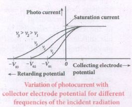
(iii) Greater the frequency of the incident radiation, larger is the corresponding stopping potential.
(iv) This implies that as the frequency is increased, the photoelectrons are emitted with greater kinetic energies so that the retarding potential needed to stop the photoelectrons is also greater.
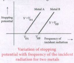
(v) Now a graph is drawn between frequent and the stopping potential for different metals (Figure).
(vi) From this graph, it is found that stopping potential varies linearly with frequency.
(vii) Below a certain frequency called their old quest no electrons are emitted; hence stopping potential is zero for that reason.
(viii) But as the frequency is increased above a threshold value, the stopping potential varies linearly with the frequency of incident light.
28.
First Theorem :
The complement of the sum of two logical inputs is equal to the product of its complements.
\(\overline { A+B } \) = \(\bar { A } .\bar { B } \)
Proof:
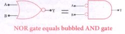
(i) The Boolean equation for NOR gate is Y = \(\overline { A+B } \)
(ii) The Boolean equation for a bubbled AND gate is Y =\(\bar { A } .\bar { B } \)
(iii) Both cases generate same outputs for same inputs. It can be verified using the following truth
| A | B | A+B | \(\overline { A+B } \) | Ā | \(\bar { B } \) | \(\bar { A } .\bar { B } \) |
| 0 | 0 | 0 | 1 | 1 | 1 | 1 |
| 0 | 1 | 1 | 0 | 1 | 0 | 0 |
| 1 | 0 | 1 | 0 | 1 | 0 | 0 |
| 1 | 1 | 1 | 0 | 0 | 0 | 0 |
(i) From the above truth table, we can conclude \(\overline { A+B } \) = \(\bar { A } .\bar { B } \)
(ii) Thus De Morgan's first theorem is proved.
(iii) Hence, a NOR gate is equal to a bubbled AND gate
Second theorem :
The complement of the product of two is equal to the sum of its complements
\(\overline { A.B } \) = \(\bar { A } +\bar { B } \)
Proof:
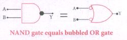
(i) The Boolean equation for NAND gate is Y = \(\overline { A.B } \)
(ii) The Boolean equation for bubbled OR gate is Y = \(\bar { A } +\bar { B } \)
(iii) A and B are the inputs and Y is the output. The above two equations produces the same output for the same inputs. It can be verified by using the truth table.
| A | B | A+B | \(\overline{\mathrm{A}. \mathrm{B}}\) | Ā | \(\bar { B } \) | \(\overline{\mathrm{A}}+\overline{\mathrm{B}}\) |
| 0 | 0 | 0 | 1 | 1 | 1 | 1 |
| 0 | 1 | 0 | 1 | 1 | 0 | 1 |
| 1 | 0 | 0 | 1 | 0 | 1 | 1 |
| 1 | 1 | 1 | 0 | 0 | 0 | 0 |
(i) From the above truth table, we can conclude \(\overline { A.B } \) = \(\bar { A } +\bar { B } \)
(ii) Thus, De Morgan's second therom is proved.
(iii) Hence, a NAND gate is equal to a bubbled OR gate.
29.
The preliminary adjustments of the spectrometer are done. The refractive index of the prism can be determined by measuring the angle of the prism (A) and the angle of minimum deviation (D).
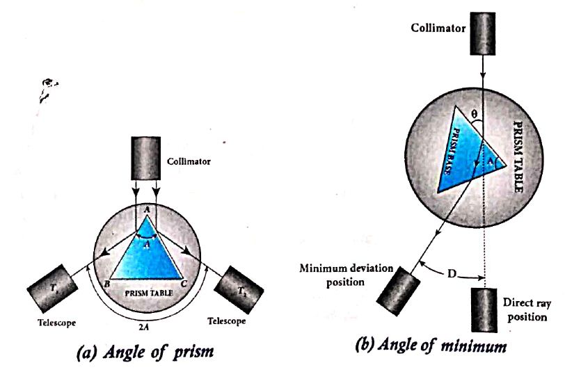
i) Angle of the prism (A):
(i) The prism is placed on the prism table with its refracting angle (A) facing the collimator as shown in Figure (a).
(ii) The slit is illuminated by sodium light (monochromatic light)
(iii)The parallel rays coming from the collimator fall on the two faces AB and AC and get reflected.
(iv) The telescope is rotated to the position T1 and T2 to capture the reflected rays and the two reading are noted
(v) The difference between these two readings gives the angle rotated by the telescope, which is twice the angle of the prism.
(vi) Half of this value gives the angle of the prism A.
ii) Angle of minimum deviation (D):
(i) The prism is placed on the prism table so that the light from the collimator falls on a refracting face, and the refracted image is observed through the telescope as shown in Figure.
(ii) The prism table is now rotated so that the angle of deviation decreases.
(iii) A stage comes when the image stops and returns on further rotation of the prism table.
(iv) This is ensured by looking through the telescope simultaneously. The reading in this position gives the minimum deviation position.
(v) Now, the prism is removed and the telescope is turned to receive the direct ray and the reading is noted.
(vi) The difference between the two readings gives the angle of minimum deviation D.
(vii) The refractive index of the material of the prism n is calculated using the formula,
\(\\ n=\cfrac { sin\left( \frac { A+D }{ 2 } \right) }{ sin\left( \frac { A }{ 2 } \right) } \) ..................(1)
The refractive index of a liquid may be determined in the same way using a hollow glass prism filled with the given liquid.
30.
Experimental setup:
(i) S is a source s1 and s2 the double slits which are at equidistances from 's'. Wavefronts from s1 and s2 spread out and overlap on other side of double slit.
(ii) When a screen is placed at a distance of about 1 meter from the slits, alternate bright and dark fringes which are equally spaced appear on the screen. These are called interference fringes or bands.
(iii) Using an eyepiece the fringes can be seen directly. At the center point O on the screen, waves from s1 and s2 travel equal distances and arrive in-phase as shown in Figure.
(iv) These two waves constructively interfere and bright fringe is observed at O. This is called cental bright fringe.
(v) When one of the slits is closed, The fringes disappear and there in uniform illumination on the screen.
(vi) This shows clearly that the bands are due to interference.
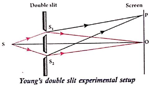
Equation for path difference :
(i) The Let d be the distance between the double slits s1 and s2 which act as coherent sources of wavelength λ.
(ii) A screen is placed parallel to the double slit at a distance D from it.
(iii) P is any point at a distance y from O.
(iv) The waves from S1 and S2 meet at P either in-phase or out-of-phase depending upon the path difference between the two waves.
.JPG)
The path difference \(\delta\) between the light waves from s1 and s2 to the point p is,
\(\delta=\mathrm{S}_{2} \mathrm{P}-\mathrm{S}_{1} \mathrm{P}\)
\(\delta=\mathrm{S}_{2} \mathrm{P}-\mathrm{MP}=\mathrm{S}_{2} \mathrm{M}\) .........(1)
\(\angle \mathrm{OCP}=\angle \mathrm{S}_{2} \mathrm{~S}_{1} \mathrm{M}=\theta\)
In right angle triangle \(\Delta \mathrm{S}_{1} \mathrm{S}_{2} \mathrm{M}\), the path difference S2M = d sin \(\theta\)
\(\delta=d \sin \theta\) ...........(2)
If the angle \(\theta\) is small, \(\sin \theta \approx \tan \theta \approx \theta\)
From the right angle triangle \(\Delta \mathrm{OCP}, \tan \theta=\frac{\mathrm{y}}{\mathrm{D}}\)
The path differences \(\delta=\frac{d y}{D}\) ...........(3)
Based on the condition of the path difference, the point P may have a bright (or) dark fringe
31.
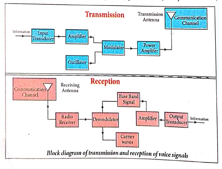
a) Information (Baseband or input signal):
i) Information can be in the form of a sound signal like speech, music, pictures, or computer data which is given as input to the input transducer.
b) Input transducer:
i) It converts the information which is in the form of sound, music, pictures or computer data into corresponding electrical signals.
ii) The electrical equivalent of the original information is called the baseband signal.
iii) The best example is the microphone that converts sound energy into electrical energy.
c) Transmitter
i) It feeds the electrical signal from the transducer to the communication channel
ii) It consists of circuits such as amplifier, oscillator, modulator, and power amplifier.
iii) Amplifier: The transducer output is very weak and is amplified by the amplifier.
iv) Oscillator: It generates high-frequency carrier wave (a sinusoidal wave) for long distance transmission into space. As the energy of a wave is proportional to its frequency, the carrier wave has very high energy.
v) Modulator: It superimposes the baseband signal onto the carrier signal and generates the modulated signal.
vi) Power amplifier: It increases the power level of the electrical signal in order to cover a large distance.
d) Transmitting antenna:
i) It radiates the radio signal into space in all directions.
ii) It travels in the form of electromagnetic waves with the speed of light.
e) Communication channel:
Communication channel is used to carry the electrical signal from transmitter to receiver with less noise or distortion.
Example: Wires, cables, optical fibres in wireline communication and free space in wireless communication.
f) Receiver:
i) The signals that are transmitted through the communication medium are received with the help of a receiving antenna and are fed into the receiver.
ii) The receiver consists of electronic circuits like demodulator, amplifier, detector etc. The demodulator extracts the baseband signal from the carrier signal.
iii) Then the baseband signal is detected and amplified using amplifiers.
iv) Finally, it is fed to the output transducer.
g) Repeaters:
i) Repeaters are used to increase the range or distance through which the signals are sent.
ii) It is a combination of transmitter and receiver.
iii) The signals are received, amplified, and retransmitted with a carrier signal of different frequency to the destination.
iv) The best example is the communication satellite in space
h) Output transducer:
i) It converts the electrical signal back to its original form such as sound, music, pictures or data.
ii) Examples of output transducers are loudspeakers, picture tubes, computer monitor, etc
32.
From the Snell's law in product form, n1 sini = n2 sinr ....(1)
The equation for this refraction at the point A is as shown in the Figure
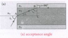
n3sin ia = n1sin ra ........(1)
(vi) To have the total internal reflection inside optical fibre, the angle of incidence at the core-cladding interface at B should be at least critical angle ie' From equation (1), for equation for the refraction at point B is,
n1 sin ic = n2 sin 90o ...(3)
n1sin ic = n2 ∵ sin 90o=1
\(sin{ i }_{ c }=\cfrac { { n }_{ 2 } }{ { n }_{ 1 } } \) ...(4)
From the right angle triangle Δ ABC,
ic = 90o - ra
Now, equation (4) becomes
\(sin\left( { 90 }^{ o }-{ r }_{ a } \right) =\cfrac { { n }_{ 2 } }{ { n }_{ 1 } } \) (or) \(cos{ r }_{ a }=\cfrac { { n }_{ 2 } }{ { n }_{ 1 } } \) ...(5)
\(sin{ r }_{ a }=\sqrt { 1-{ cos }^{ 2 }{ r }_{ a } } \)
Substituting for cos ra
\(sin{ r }_{ a }=\sqrt { 1-\left( \cfrac { { n }_{ 2 } }{ { n }_{ 1 } } \right) ^{ 2 } } =\sqrt { \cfrac { { n }_{ 1 }^{ 2 }-{ n }_{ 2 }^{ 2 } }{ { n }_{ 1 }^{ 2 } } } \) ...(6)
Substituting this in equation
\({ n }_{ 3 }{ sini }_{ a }={ n }_{ 1 }\sqrt { \cfrac { { n }_{ 1 }^{ 2 }-{ n }_{ 2 }^{ 2 } }{ { n }_{ 1 }^{ 2 } } } =\sqrt { { n }_{ 1 }^{ 2 }-{ n }_{ 2 }^{ 2 } } \) ...(7)
On further simplification
\(sini_{ a }=\cfrac { \sqrt { { n }_{ 1 }^{ 2 }-{ n }_{ 2 }^{ 2 } } }{ n_{ 3 } } \) (or) \(\quad { i }_{ a }=\sqrt { \cfrac { { n }_{ 1 }^{ 2 }-{ n }_{ 2 }^{ 2 } }{ { n }_{ 3 }^{ 2 } } } \) ...(8)
\(\therefore{ i }_{ a }={ sin }^{ -1 }\left( \sqrt { \cfrac { { n }_{ 1 }^{ 2 }-{ n }_{ 2 }^{ 2 } }{ { n }_{ 3 }^{ 2 } } } \right) \) ...(9)
If outer medium is air, then n3 = 1. The acceptance angle ia becomes
\({ i }_{ a }={ sin }^{ -1 }\left( \sqrt { { n }_{ 1 }^{ 2 }-{ n }_{ 2 }^{ 2 } } \right) \) ..(10)
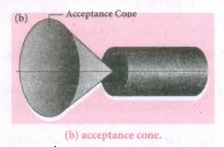
Light can have any angle of incidence from 0 to ia with the normal at the end of the optical fibre forming a conical shape called acceptance cone. In the equation (6), the term (n3sinia) is called numerical aperture NA of the optical fibre.
\(NA={ n }_{ 3 }{ sini }_{ a }=\sqrt { { n }_{ 1 }^{ 2 }-{ n }_{ 2 }^{ 2 } } \)
If outer medium is ab then n3 = 1
The numerical aperture NA becomes,
\(NA={ sini }_{ a }=\sqrt { { n }_{ 1 }^{ 2 }-{ n }_{ 2 }^{ 2 } } \)
33.
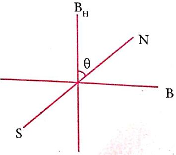
(i) When a magnetic needle or magnet is freely suspended in two mutually perpendicular uniform magnetic fields, it will come to rest in the direction of the resultant of the two fields.
(ii) Let B be the magnetic field produced by passing current through the coil of the tangent galvanometer and BH be the horizontal component of earth's magnetic field.
(iii) Under the action of two magnetic fields, the needle comes to rest making angle with BH , such that
B = BH tan \(\theta\) .........(1)
Where B ⇒ magnetic field produced by current
BH ⇒ horizontal component of earth's magnetic field
Construction:
(i) Copper coil of wire wound on a non-magnetic circular frame such as brass or wood. Compass box is kept at centre.
(ii) This compass box consists of pivoted magnet and aluminum pointer.
(iii) This compass box is having circular scale graduated with four quadrants.
Working:
(i) Two magnetic fields are perpendicular to each other.
(ii) Magnetic induction due to the current in the coil acting to normal to the plane of the coil.
(iii) Magnetic induction at the centre of the coil,
\(B=μ_o\frac{NI}{2R}\) .....(2)
Sub. eqn.(1) in eqn. (2)
\(B_H tan \theta =μ_o\frac{NI}{2R}\)
\(B_H =μ_o\frac{NI}{2R}\frac{1}{tan\theta}\)
34.
(i) Let 'R' be the radius of a current carrying circular loop.
(ii) I be the current flowing through the wire.
(iii) Let P be a point on the axis of the circular coil at a distance z from its centre 'O'
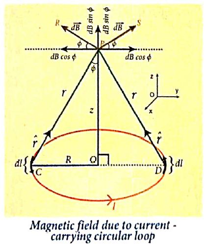
(iv) Take two diametrically opposite element \(\vec { dl } \) at C and D. According to Biot-Savart's law, the magnetic field at P due to the current element at C is
\(d \vec{B}=\frac{\mu_0}{4 \pi} \frac{I d \vec{l} \times \hat{r}}{r^2}\)
The magnitude of \( { d\vec B } \)is
\(d \vec{B}=\frac{\mu_0}{4 \pi} \frac{I d l \sin \theta}{r^2}=\frac{\mu_0}{4 \pi} \frac{I d l}{r^2}\)
where θ is the angle between \(I\vec { dl } \) and \(\vec { r } \). Here, θ = 90o.
\(\vec{B} =\int d \vec{B}=\int d B \sin \phi \hat{k} \)
\(\vec{B} =\frac{\mu_o I}{4 \pi} \int \frac{d l}{r^2} \sin \phi \hat{k} \)
\(\text {But, } \cos \theta =\frac{R}{\left(R^2+z^2\right)^{\frac{1}{2}}} \text { (using Pythagoras theorem) }\)
From ΔOCP
\(\sin \phi=\frac{R}{\left(R^2+z^2\right)^{1 / 2}} \text { and } r^2=R^2+z^2.\)
Substituting these in the above equation, we get,
\(\vec{B}=\frac{\mu_0 I}{4 \pi} \frac{R}{\left(R^2+z^2\right)^{3 / 2}} \hat{k}\left(\int d l\right)\)
If we integrate the line element from 0 to 2πR, we get the net magnetic field \(\vec{B}\) at any point P due to the current - carrying circular loop,
\(\vec{B}=\frac{\mu_0 I}{2} \frac{R^2}{\left(R^2+z^2\right)^{3 / 2}} \hat{k}\)
If the circular coil contains N turns, then the magnetic field is
\(\vec{B}=\frac{\mu_0 N I}{2} \frac{R^2}{\left(R^2+z^2\right)^{3 / 2}} \hat{k}\)
The magnetic field at the centre of the coil is,
\(\vec{B}=\frac{\mu_0NI}{2R}\hat k\) since z= 0
35.
During LC oscillations in LC circuits, the energy of the system oscillates between the electric field of the capacitor and the magnetic field of the inductor. Although, these two forms of energy vary with time, the total energy remains constant
It means that LC oscillations take place in accordance with the law of conservation of energy.
Total energy, \(U=U_E+U_B=\frac{q^{\prime}}{2 C}+\frac{1}{2} Li^2\)
Let us consider 3 different stages of LC oscillations and calculate the total energy of the system.
Case (i): When the charge in the capacitor, q = Qmand the current through the inductor, i = 0, the total energy is given by,
\(U=\frac{Q_m^2}{2 C}+0=\frac{Q_{-}^2}{2 C}\) ....(1)
The total energy is wholly electrical.
Case (ii): When charge = 0, current = Im, the total energy is,
\(U =0+\frac{1}{2} L I_m^2=\frac{1}{2} L I_m^2 \)
\( =\frac{L}{2} \times\left(\frac{Q_m^2}{L C}\right)=\frac{Q_m^2}{2 C} \quad \text { since } I_m=Q_m \omega=\frac{Q_m}{\sqrt{L C}}\) ...(2)
The total energy is wholly magnetic.
Case (iii): When charge = q, current = i, the total energy is,
\(U=\frac{q^2}{2 C}+\frac{1}{2} L i^2\)
Since, \(q=Q_m \cos \omega t, i=-\frac{d q}{d t}=Q_m \omega \sin \omega t.\)
The negative sign in current indicates that the charge in the capacitor decreases with time.
\(U=\frac{Q_{m}^2 \cos ^2 \omega t}{2 C}+\frac{L_\omega^2 Q_m^2 \sin ^2 \omega t}{2}\)
\(=\frac{Q_{m}^2 \cos ^2 \omega t}{2 C}+\frac{L Q_m^2 \sin ^2 \omega t}{2} \quad [since \omega^2=\frac{1}{LC}]\)
\(=\frac{Q_{m}^2}{2C} (cos ^2 \omega t+ sin^2 \omega t)\)
\(U=\frac{Q_{m}^2}{2C}\) .....(3)
From above three cases, it is clear that the total energy of the system remains constant.
36.
(i) In some AC generators may have more than one coil in the armature core and each coil producesan alternating emf. In these generators, more than one emf is produced. Thus, they are called poly-phase generators.
(ii) If there are two alternating emfs produced in a generator, it is called two-phase generator, it is called two-phase generator. In some AC generators, there are three separate coils, which owould give three separate emfs. Hence, they are called three-phase AC generators.
(iii) In the simplified construction of three-phase AC generator, the armature core has 6 slots, cut on its inner rim. Each slot is 60° away from one another. Six armature conductors are mounted in these slots.The conductors 1 and 4 are joined in series to form coil 1. The conductors 3and 6 form coil 2 while the conductors 5 and 2 form coil 3. So, these coils arerectangular in shape and are 120° apart from one another.
(iv) The initial position of the field magnet is horizontal and field direction is perpendicular to the plane of the coil 1. As it is seen in single phase AC generator, when field magnet is rotated from that position in clockwise direction, alternating emf ε1 in coil 1 begins a cycle from origin O. This is shown in Figure.
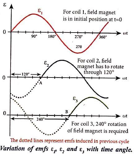
(v) The corresponding cycle for alternating emf ε2 in coil 2 starts at point A after field magnet has rotated through 120°. Therefore, the phase difference between ε1 and ε2 is 120°. Similarly, emf ε3 in coil 3 would begin its cycle at point B after 240° rotation of field magnet from initial position. Thus these emfs produced in the three phase AC generator have 120° phase difference between one another.
37.
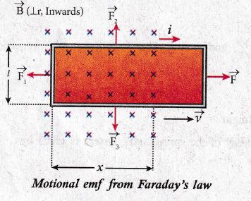
(i) Consider a rectangular conducting loop of width 1 in a uniform magnetic field \(\vec { B } \) which is perpendicular to the plane of the loop and is directed inwards.
(ii) A part of the loop is in the magnetic field while the remaining part is outside the loop as shown in Figure.
(iii) When the loop is pulled with a constant velocity \(\vec { v } \) to the right, the area of the portion of the loop within the magnetic field will decrease.
(iv) Thus, the flux linked with the loop will also decrease. According to Faraday's law, an electric current is induced in the loop which flows in a direction so as to oppose the pull of the loop.
(v) Let x be the length of the loop which is still within the magnetic field, then its area is lx. The magnetic flux linked with the loop is
\({ \phi }_{ B }=\int _{ A }^{ }{ B.d } \vec { A } =BAcos\theta \)
Here θ = 0o and cos 0o = 1
= BA
\({ \phi }_{ B }=Blx\)
(vi) As this magnetic flux decreases due to the movement of the loop, the magnitude of the induced emf is given by
\(\varepsilon =\frac { d{ \Phi }_{ B } }{ dt } =\frac { d }{ dt } (Blx)\)
(vii) Here, both B and 1 are constants. Therefore,
\(\varepsilon =Bl\frac { dx }{ dt } \)
ε = Blv
where \(v=\frac { dx }{ dt } \) is the velocity of the loop. This emf is known as motional emf since it is produced due to the movement of the loop in the magnetic field.
38.

12th Standard Syllabus & Materials
12th Standard
TN 12th Computer Applications களப்பெயர் முறைமை (DNS) Sample Question Papers Study Material - QB365 Set A
NEW12th Standard
TN 12th Computer Applications வலையமைப்பு எடுத்துக்காட்டுகள் மற்றும் நெறிமுறைகள் Sample Question Papers Study Material - QB365 Set A
NEW12th Standard
TN 12th Computer Applications கணினி வலையமைப்பு ஓர் அறிமுகம் Sample Question Papers Study Material - QB365 Set A
NEW12th Standard
TN 12th Computer Applications PHP-உடன் MySQL-ஐ இணைத்தல் Sample Question Papers Study Material - QB365 Set A



Tamilnadu Stateboard 12th Standard Subjects

Maths

Chemistry
Physics

Biology

Computer Science

Business Maths and Statistics

Economics

Commerce

Accountancy

History

Computer Applications
Biology
Computer Technology
Computer Applications
Computer Science
Business Maths and Statistics
Commerce
Economics
Maths
Chemistry
Physics
Computer Technology
History
Accountancy

Tamil

English

French
Tamilnadu Stateboard Standards

