
 100% FREE ACCESS
12th Standard Syllabus & Materials
12th Standard
TN 12th Maths Applications of Matrices and Determinants Sample Question Papers Study Material - QB365 Set A
NEW12th Standard
TN 12th Computer Applications மின்னணு தரவு பரிமாற்றம் Sample Question Papers Study Material - QB365 Set A
NEW12th Standard
TN 12th Computer Applications மின் - வணிக பாதுகாப்பு அமைப்புகள் Sample Question Papers Study Material - QB365 Set A
NEW12th Standard
TN 12th Computer Applications மின்னணு செலுத்தல் முறைகள் Sample Question Papers Study Material - QB365 Set A
NEW12th Standard
TN 12th Computer Applications மின் - வணிகம் Sample Question Papers Study Material - QB365 Set A
NEW12th Standard
TN 12th Computer Applications திறந்த மூல கருத்துருக்கள் Sample Question Papers Study Material - QB365 Set A

Published on: 01/09/2022
QB365 provides a detailed and simple solution for every Possible Book Back Questions in Class 12 Physics Subject - Magnetism and Magnetic Effects of Electric Current, English Medium. It will help Students to get more practice questions, Students can Practice these question papers in addition to score best marks.
Download Tamil Nadu 12th Standard Physics question papers, model tests, one-mark questions, important questions, and public exam papers in PDF format. Free study materials and answer keys for TN State Board students.
Questions + Answers key
Take MCQ Physics Test1.
Derive the expression for the force on a current-carrying conductor in a magnetic field.
2.
Compare the properties of soft and hard ferromagnetic materials.
3.
Derive the expression for the force between two parallel, current - carrying conductors.
4.
5.
Calculate the magnetic field inside and outside of the long solenoid using Ampere’s circuital law.
6.
Discuss the conversion of galvanometer into an ammeter and also a voltmeter.
7.
What is tangent law? Discuss in detail.
8.
Discuss the working of cyclotron in detail.
9.
Find the magnetic field due to a long straight conductor using Ampere’s circuital law.
10.
Obtain the magnetic field at a point on the equatorial line of a bar magnet.
11.
Calculate the magnetic field at a point on the axial line of a bar magnet.
12.
Obtain a relation for the magnetic field at a point along the axis of a circular coil carrying current using Biot-Savart law.
13.
Deduce the relation for the magnetic field at a point due to an infinitely long straight conductor carrying current using Biot-Savart law.
14.
Discuss Earth’s magnetic field in detail.
15.
Show that for a straight conductor, the magnetic field
\(\overset { \rightarrow }{ B } =\frac { { \mu }_{ ° }I }{ 4\pi a } (cos\varphi _{ 1 }-cos\varphi _{ 2 })\hat { n } \)
\(=\frac { { \mu }_{ ° }I }{ 4\pi a } (sin{ \theta }_{ 1 }+sin{ \theta }_{ 2 })\hat { n } \)
16.
Compute the torque experienced by a magnetic needle in a uniform magnetic field.
1.
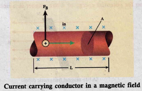
When a current carrying conductor is placed in a magnetic field, the force experienced by the wire is equal to the sum of Lorentz forces on the individual charge carries in the conductor. Consider a small segment of conductor of length dl, cross-sectional area A and current I as shown in figure. The free electron drift opposite to the direction of current. So the relation between current I and magnitude of drift velocity vd is
\(I=n e A v_{d}\) ........(1)
If the conductor is kept in a magnetic field \(\vec{B}\) , then average force experienced by the charge (here, electron ) on the conductor is
\(\vec{F}=-e\left(\vec{\nu}_{d} \times \vec{B}\right)\)
Let n be the number of free electrons present in unit volume, therefore
\(\mathrm{n}=\frac{N}{V}\)
where, N is the number of free electrons in the small element of volume V = A dl
Hence Lorentz force \(\overrightarrow{d F}=-e n A d l\left(\overrightarrow{v_{d}} \times \vec{B}\right)\)
Current element,
\(I{\vec d F}=-e n A \vec v_dd l\)
\(d \vec{F}=(I d \vec{l} \times B)\) ........(2)
The force on a straight current carrying conducting wire of length I placed in a uniform magnetic field is,
\(\vec{F}=(I\vec{l} \times \vec{B})\)
In magnitude,
\(\mathrm{F}=\mathrm{BI} l \sin \theta\)
(a) If the conductor is placed along the direction of the magnetic field, the angle between them is \(\theta\) = 0o.
∴ F = 0
(b) If the conductor is placed perpendicular to the magnetic field, the angle between them is \(\theta\) = 90o
∴ F = BIl. (maximum)
2.
| S.No. | Properties | Soft ferromagnetic materials | Hard ferromagnetic materials |
| i | When external field is removed | Magnetisation disappears | Magnetisation persists |
| ii | Area of the loop | Small | Large |
| iii | Retentivity | Low | High |
| iv | Coercivity | Low | High |
| v | Susceptibility and magnetic permeability | High | Low |
| vi | Hysteresis loss | Less | More |
| vii | Uses | Solenoid core, transformer core and electromagnets | Permanent magnets |
| viii | Examples | Soft iron, Mumetal, Stalloy etc. | Carbon Steel, Alnico, Lodestone etc |
3.
Two long straight parallel current-carrying conductors separated by a distance r are kept in air medium. Let I1 and I2 be the electric currents passing through the conductors A and B is same direction (i.e., along z-direction) respectively. The net magnetic field at a distance r due to current I1 in conductor A is
\(\vec{B}_{1}=\frac{\mu_{o} I_{1}}{2 \pi r}(-\hat{\mathrm{i}})=-\frac{\mu_{o} I_{1}}{2 \pi r} \hat{i}\)
.JPG)
From thumb rule, the direction of magnetic field is perpendicular to the plane of the paper and inwards (arrow into the page ⊗) i.e. along negative \(\vec{i}\)direction
Let us consider a small elemental length dl in conductor B at which the magnetic field \(\vec{B}_1\) present, From equation \(\overrightarrow{d F}=(I \overrightarrow{d l} \times \vec{B})\)
Lorentz force on the element dl of conductor B is
\(\overrightarrow{d F}=\left(I_{2} d \vec{l} \times \vec{B}_{1}\right)=-I_{2} d l \frac{\mu_{o} I_{1}}{2 \pi r}(\hat{k} \times \hat{i})=-\frac{\mu_{o} I_{1} I_{2} d l}{2 \pi r} \hat{j}\)
Therefore the force on dl of wire conductor B is directed towards the conductor A. So the element of length dl in B is attracted towards the conductor A. Hence, the force per unit length of the conductor B due to the current in the conductor A is,
\(\frac{\vec{F}}{l}=-\frac{\mu_{o} I_{1} I_{2}}{2 \pi r} \hat{j}\)
Similarly, the net magnetic induction due to current I2 (in conductor B) at a distance r in the elemental length dl of conductor A is
\(\vec{B}_{2}=\frac{\mu_{o} I_{2}}{2 \pi r} \hat{i}\)
From the thumb rule direction of magnetic field is perpendicular to the plane of the paper and outwards (arrow out to the page ⊙) i.e., along positive \(\vec{i}\)direction.
Hence the magnetic force at element dl of the conductor A is,
\(\vec{dF} =\left(I_{1} \vec{d} l \times \vec{B}_{2}\right)=I_{1} d l \frac{\mu_{o} I_{2}}{2 \pi r}(\hat{k} \times \hat{i}) \)
\(=\frac{\mu_{o} I_{1} I_{2} d l}{2 \pi r} \hat{j} \)
Therefore the force on dl of conductor A is directed towards the conductor B. So the length dl is attracted towards the conductor B as shown in Figure.
.JPG)
The force acting per unit length of the conductor A due to the conductor B is
\(\frac{\vec{F}}{l}=-\frac{\mu_{0} I_{1} I_{2}}{2 \pi r} \hat{j}\)
Attractive force: The direction of electric current is same.
Repulsive force: The direction of electric current is opposite.
4.
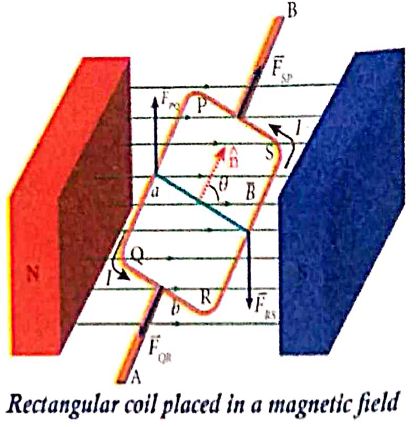
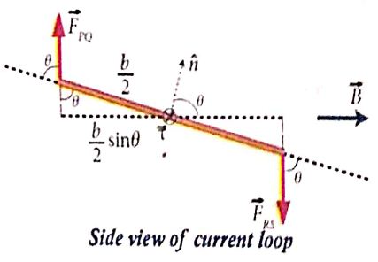
5.
Consider a solenoid of length L having N turns. The diameter of the solenoid is assumed to be much smaller when compared to its length and the coil is wound very closely.
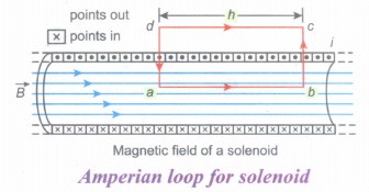
Consider a rectangular loop abcd. Then from Ampere's circuital law,
\(\oint _{ C }^{ }{ \vec { B } .\vec { dl } } \) = μ0 Ienclosed = μ0 x (total current enclosed by Amperian loop)
The left hand side of the equation is
\(\oint _{ C }^{ }{ \vec { B } .\vec { dl } } =\int _{ a }^{ b }{ \vec { B } .\vec { dl } } +\int _{ b }^{ c }{ \vec { B } .\vec { dl } } +\int _{ c }^{ d }{ \vec { B } .\vec { dl } } +\int _{ d }^{ a }{ \vec { B } .\vec { dl } } \)
Elemental lengths bc and da are perpendicular to magnetic field.
\(\therefore \int _{ b }^{ c }{ \vec { B } .\vec { dl } } =\int _{ b }^{ c }{ |\vec { B } ||\vec { dl } | } cos 90^o = 0\)
similarly,
\(\int _{ d }^{ a }{ \vec { B } .\vec { dl } } = 0\)
Since the magnetic field outside the solenoid is zero,
\(\int _{ c }^{ d }{ \vec { B } .\vec { dl } } =0\) and
\(\int _{ a }^{ b }{ \vec { B } .\vec { dl } } =BL \quad \quad (\because \theta =0^o)\)
Let I be the current passing through the solenoid of N turns, then
\(\int _{ a }^{ b }{ \vec { B } .\vec { dl } } = BL = μ_o NI ⇒ B = μ_o\frac {NI}{L}\)
The number of turns per unit length is given by \(\frac { N }{ L } \) = n, Then
B = \(\mu_o \frac { nLI }{ L } \) = μ0nI
Since n is a constant for a given solenoid and μ0 is also constant. For a fixed current I, the magnetic field inside the solenoid is also a constant.
6.
(i) Galvanometer to an Ammeter:
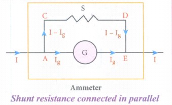
(i) Ammeter is an instrument used to measure current flowing in the electrical circuit.
(ii) The Ammeter must offer low resistance such that it will not change the current passing through it. So, ammeter is connected in series to measure the circuit current.
(iii) A galvanometer is converted into an ammeter by connecting a low resistance in parallel with the galvanometer.
(iv) Let I be the current passing through the circuit. When current I reaches the junction A, it divides into two components.
a) Ig → Current passing through the galvanometer
b) I - Ig → Current passing through the shunt resistance.
(v) The potential difference across the galvanometer is same as the potential difference across the shunt resistance.
\(\mathrm{V}_{\text {galvanometer }} =\mathrm{V}_{\text {shunt }} \)
\(\Rightarrow \mathrm{I}_{\mathrm{g}} \mathrm{R}_{\mathrm{g}} =\left(\mathrm{I}-\mathrm{I}_{g}\right) \mathrm{S} \)
\(\mathrm{S} =\frac{I_{g}}{\left(I-I_{g}\right)} R_{g} \) (or)
\(\mathrm{I}_{\mathrm{g}}=\frac{S}{S+R_{g}} I \Rightarrow I_{g} \propto I\)
Since, the deflection in the galvanometer is proportional to the current passing through it.
\(\theta=\frac{1}{G} I_{g} \Rightarrow \theta \propto I_{g} \Rightarrow \theta \propto I\)
Where, Rg → Galvanometer resistance, S → Shunt resistance.
Since shunt resistance is connected in parallel to galvanometer,
Effective resistance,\(\frac{1}{R_{e f f}}=\frac{1}{R_{g}}+\frac{1}{S} \Rightarrow R_{e f f}=\frac{R_{g} S}{R_{g}+S}=R_{a}\)
Ra ⇒ low resistance. An ideal ammeter has zero resistance.
The percentage error in measuring a current through an ammeter is,
\(\frac{\Delta I}{I} \times 100 \%=\frac{I_{i d e a l}-I_{a c t u a l}}{I_{a c t u a l}} \times 100 \%\)
(ii) Galvanometer to a voltmeter:
i) A voltmeter is an instrument used to measure potential difference across any two points in the electrical circuits.
ii) Voltmeter must have high resistance and when it is connected in parallel, it will rot draw appreciable current so that it will indicate the true potential difference.
iii) A galvanometer is converted into a voltmeter by connecting high resistance Rh in series with galvanometer.
iv) Let Rg be the resistance of galvanometer and Ig be the current with which the galvanometer produces full scale deflection.
v) Since the galvanometer is connected in series with high resistance, the current in the electrical circuit is same as the current passing through the galvanometer.
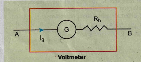
\(\mathrm{I}=\mathrm{I}_{\mathrm{g}} \)
\(\mathrm{I}=I_{g} \Rightarrow I_{g}=\frac{\text { potential difference }}{\text { total resistance }} \)
Since the galvanometer and high resistance are connected in series, the voltmeter resistance is,
\(R_{v} =R_{g}+R_{h} \)
Therefore,
\(I_{g} =\frac{V}{R_{g}+R_{h}} \)
\(\Rightarrow R_{h} =\frac{V}{I_{g}}-R_{g} \)
Note that \(I_{g} \propto V\)
Rh is very large. An ideal voltmeter has infinite resistance
7.
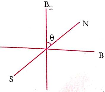
(i) When a magnetic needle or magnet is freely suspended in two mutually perpendicular uniform magnetic fields, it will come to rest in the direction of the resultant of the two fields.
(ii) Let B be the magnetic field produced by passing current through the coil of the tangent galvanometer and BH be the horizontal component of earth's magnetic field.
(iii) Under the action of two magnetic fields, the needle comes to rest making angle with BH , such that
B = BH tan \(\theta\) .........(1)
Where B ⇒ magnetic field produced by current
BH ⇒ horizontal component of earth's magnetic field
Construction:
(i) Copper coil of wire wound on a non-magnetic circular frame such as brass or wood. Compass box is kept at centre.
(ii) This compass box consists of pivoted magnet and aluminum pointer.
(iii) This compass box is having circular scale graduated with four quadrants.
Working:
(i) Two magnetic fields are perpendicular to each other.
(ii) Magnetic induction due to the current in the coil acting to normal to the plane of the coil.
(iii) Magnetic induction at the centre of the coil,
\(B=μ_o\frac{NI}{2R}\) .....(2)
Sub. eqn.(1) in eqn. (2)
\(B_H tan \theta =μ_o\frac{NI}{2R}\)
\(B_H =μ_o\frac{NI}{2R}\frac{1}{tan\theta}\)
8.
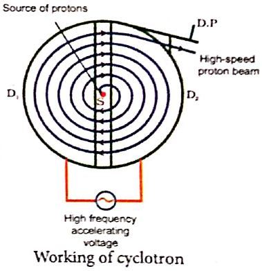
Cyclotron:
Device used to accelerate the charged particles to gain large kinetic energy.
Principle:
When a charged particle moves perpendicular to the magnetic field, it experiences magnetic Lorentz force.
Construction:
(i) The particles are allowed to move in between two semi-circular metal containers called Dees (hollow D - shaped objects).
(ii) The uniform magnetic field is controlled by an electromagnet. The direction of magnetic field is normal to the plane of the Dees.
(iii) Source is kept between two Dees.
(vi) Dees are connected to high frequency alternating potential difference.
Working:
(i) The ion ejected from source is positively charged.
(ii) It is accelerated towards negative potential Dees
(iii) This ion undergoes a circular path.
(iv) At this time, the polarities of the Dees are reversed, so that the ion is now accelerated towards Dee-2 with a greater velocity. For this circular motion, the centripetal force of the charged particle q is provided by Lorentz force.
\(\frac { m{ v }^{ 2 } }{ r } \) = qvB
⇒ r = \(\frac { m }{ qB } \)v ........(1)
⇒ r ∝ v
(v) If radius of the circular paths, increases, velocity also increases particles undergo spiral path with increasing radius.
(vi) When the frequency f at which the positive ion ciculates in the magnetic field must be equal to the constant frequency of the electrical oscillator fosc. This is called Resonance condition.
From equation, f = \(\frac { qB }{ 2\pi m } \) we have
fosc = \(\frac { qB }{ 2\pi m } \),
The time period of oscillation is
T = \(\frac { 2\pi m }{ qB } \)
The kinetic energy of the charged particle is,
KE = \(\frac { 1 }{ 2 } mv^{ 2 }=\frac { { q }^{ 2 }B^{ 2 }{ r }^{ 2 } }{ 2m } \) ........(2)
Limitations:
(i) The speed of ion is limited.
(ii) Electron cannot be accelerated.
(iii) Uncharged particles cannot be accelerated.
9.
i) Let I be current flowing in infinite length of conductor.
ii) Amperian loop is constructed in the form of a circular shape at a distance r from the centre of the conductor.
iii) dl is the line element along the loop.
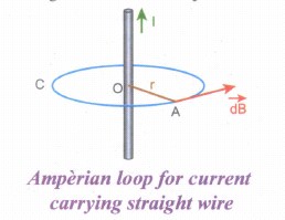
From the Ampere's law \(\oint _{ C }^{ }{ \vec { B } .\vec { dl } } \) = μoI
Hence, the angle between magnetic field vector and line element is zero. Therefore, Here, the angle between magnetic field vector and line element is zero.
\(\oint _{ C }^{ }{ {B dl } } \) = μoI
For a circular loop, the circumference is 2πr, which implies,
B\(\int _{ 0 }^{ 2\pi r }{ dl } \) = μoI
\(\vec { B } \).2πr = μoI
B = \(\frac { { \mu }_{ 0 }I }{ 2\pi r } \)
In vector form, the magnetic field is
\(\vec { B } =\frac { { \mu }_{ 0 }I }{ 2\pi r } \hat { n } \)
where \(\hat { n } \) is the unit vector along the tangent to the Amperian loop as shown in the Figure.
10.
(i) Consider a bar magnet NS and pole strength qm and distance 2l.
(ii) Let C be point along the equatorial line.
(iii) The magnetic field at a point C (lines along the equatorial line) at a distance r from the geometrical center O of the magnet can be computed by keeping unit north pole (qmC = 1 A m) at C.
\(\vec { { B }_{ N } } =-{ B }_{ N }cos\theta \hat { i } +{ B }_{ N }sin\theta \hat { j } \) .....(1)
where BN = \(\frac { { \mu }_{ 0 } }{ 4\pi } \frac { { q }_{ m } }{ r^{ '2 } } \)
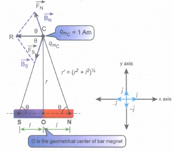
The magnetic field at C due to south pole is,
\(\vec { { B }_{ s } } =-{ B }_{ s }cos\theta \hat { i } -{ B }_{ s }sin\theta \hat { j } \) .....(2)
where Bs = \(\frac { { \mu }_{ 0 } }{ 4\pi } \frac { { q }_{ m } }{ r^{ '2 } } \)
From equations (1) and (2), the net magnetic field at point C due to dipole is \(\vec { { B } } =\vec { { B }_{ N } } +\vec { { B }_{ S } } \).
\(\vec { { B } } =-({ B }_{ N }+{ B }_{ S })cos\theta \hat { i } \) Since, BN = BS
\(\vec { { B } } =-\frac { { 2\mu }_{ 0 } }{ 4\pi } \frac { { q }_{ m } }{ r'^{ 2 } } cos\theta \hat { i } =-\frac { 2{ \mu }_{ 0 } }{ 4\pi } \frac { { q }_{ m } }{ ({ r }^{ 2 }+l^{ 2 }) } cos\theta \hat { i } \) ....(3)
In a right angle triangle NOC, as shown in the figure,
cosθ=\(\frac { adjacent }{ hypotenuse } =\frac { 1 }{ r' } =\frac { 1 }{ ({ r }^{ 2 }+{ l }^{ 2 })^{ \frac { 1 }{ 2 } } } \) .........(4)
Substituting equation (4) in equation (3) we get
\(\vec { B } =-\frac { { \mu }_{ 0 } }{ 4\pi } \frac { { q }_{ m }\times (2l) }{ ({ r }^{ 2 }+{ l }^{ 2 })^{ \frac { 3 }{ 2 } } } \hat { i } \) ........(5)
Since, magnitude of magnetic dipole moment is \(|\vec { { p }_{ m } } |\) = pm = qm. 2l and substituting in equation (5), we get the magnetic field at a point C is
\( { { \vec B }_{ equatorial } } =-\frac { { \mu }_{ 0 } }{ 4\pi } \frac { { p }_{ m } }{ ({ r }^{ 2 }+{ l }^{ 2 })^{ \frac { 3 }{ 2 } } } \hat { i } \) ........(6)
If the distance between two poles in a bar magnet are small (looks like short magnet) when compared to the distance between geometrical center O of bar magnet and the location of point C i.e., r >>l, then,
(r2 + l2)3\2 ≈ r3 ..........(7)
Therefore, using equation (7) in equation (6), we get
\( { { \vec B }_{ equatorial } } =-\frac { { \mu }_{ 0 } }{ 4\pi } \frac { { p }_{ m } }{ r^{ 3 } } \hat { i } \)
In general, the magnetic field at equatorial point is given by
\({ { \vec B }_{ equatorial } } =-\frac { { \mu }_{ 0 } }{ 4\pi } \frac { { \vec p }_{ m } }{ r^{ 3 } } \) Since pm\(\hat { i } =\vec { { p }_{ m } } \), .......(8)
11.
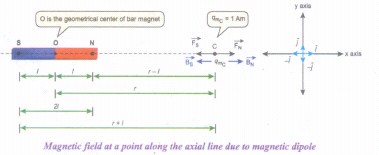
(i) Consider a bar magnet NS whose pole strength is qm and length is 2l.
(ii) Let C be the point along axis of maget.
(iii) The magnetic field at a point C (lies along the axis of the magnet) at a distance r from the geometrical center O of the bar magnet can be computed by keeping unit north pole (qmc = 1 A m) at C.
The magnetie field at C due to the north pole is,
\(\vec { { B }_{ N } } =\frac { { \mu }_{ 0 } }{ 4\pi } \frac { { q }_{ m } }{ (r-l)^{ 2 } } \hat { i } \)
where (r - I) is the distance between north pole of the bar magnet and unit north pole at C. The magnetic field at C due to the south pole is,
\(\vec { { B }_{ S } } =-\frac { { \mu }_{ 0 } }{ 4\pi } \frac { { q }_{ m } }{ (r+l)^{ 2 } } \hat { i } \)
where (r + I) is the distance between south pole of the bar magnet and unit north pole at C. The net magnetic field due to magnetic dipole at a point C
\(\vec { B } =\vec { { B }_{ N } } +\vec { B_{ S } } \)
\(\vec { B } =\frac { { \mu }_{ 0 } }{ 4\pi } \frac { { q }_{ m } }{ (r-l)^{ 2 } } \hat { i } +\left(- \frac { { \mu }_{ 0 } }{ 4\pi } \frac { { q }_{ m } }{ (r+l)^{ 2 } } \hat { i } \right) \)
\(\vec { B } =\frac { { \mu }_{ 0 }{ q }_{ m } }{ 4\pi } \left( \frac { 1 }{ (r-l)^{ 2 } } -\frac { 1 }{ (r+l)^{ 2 } } \right) \hat { i } \)
\(\vec { B } =\frac { { \mu }_{ 0 }2r }{ 4\pi } \left( \frac { { q }_{ m }.(2l) }{ ({ r }^{ 2 }-{ l }^{ 2 })^{ 2 } } \right) \hat { i } \)
Since, magnitude of magnetic dipole moment is \(|\vec { { p }_{ m } } |\) = pm = qm. 2l the magnetic field at a point C can be written as,
\(\vec { { B }_{ axial } } =\frac { { \mu }_{ 0 } }{ 4\pi } \left( \frac { 2rp_{ m } }{ { (r^2-l^2)}^{ 2 } } \right) \hat { i } \)
If r >> I then, (r2 - l2)2 ≈ r4
\( { { \vec B }_{ axial } } =\frac { { \mu }_{ 0 } 2r}{ 4\pi } \left( \frac { p_{ m } }{ { r }^{ 4 } } \right) \hat { i } =\frac { { \mu }_{ 0 } }{ 4\pi }[ \frac { 2 \vec p_{ m } }{ { r }^{ 3 }}] \)
∵ \(\vec { { p }_{ m } } =p_{ m }\hat { i } \).
12.
(i) Let 'R' be the radius of a current carrying circular loop.
(ii) I be the current flowing through the wire.
(iii) Let P be a point on the axis of the circular coil at a distance z from its centre 'O'
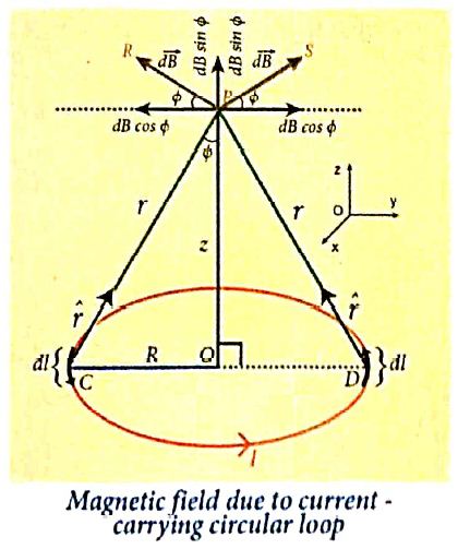
(iv) Take two diametrically opposite element \(\vec { dl } \) at C and D. According to Biot-Savart's law, the magnetic field at P due to the current element at C is
\(d \vec{B}=\frac{\mu_0}{4 \pi} \frac{I d \vec{l} \times \hat{r}}{r^2}\)
The magnitude of \( { d\vec B } \)is
\(d \vec{B}=\frac{\mu_0}{4 \pi} \frac{I d l \sin \theta}{r^2}=\frac{\mu_0}{4 \pi} \frac{I d l}{r^2}\)
where θ is the angle between \(I\vec { dl } \) and \(\vec { r } \). Here, θ = 90o.
\(\vec{B} =\int d \vec{B}=\int d B \sin \phi \hat{k} \)
\(\vec{B} =\frac{\mu_o I}{4 \pi} \int \frac{d l}{r^2} \sin \phi \hat{k} \)
\(\text {But, } \cos \theta =\frac{R}{\left(R^2+z^2\right)^{\frac{1}{2}}} \text { (using Pythagoras theorem) }\)
From ΔOCP
\(\sin \phi=\frac{R}{\left(R^2+z^2\right)^{1 / 2}} \text { and } r^2=R^2+z^2.\)
Substituting these in the above equation, we get,
\(\vec{B}=\frac{\mu_0 I}{4 \pi} \frac{R}{\left(R^2+z^2\right)^{3 / 2}} \hat{k}\left(\int d l\right)\)
If we integrate the line element from 0 to 2πR, we get the net magnetic field \(\vec{B}\) at any point P due to the current - carrying circular loop,
\(\vec{B}=\frac{\mu_0 I}{2} \frac{R^2}{\left(R^2+z^2\right)^{3 / 2}} \hat{k}\)
If the circular coil contains N turns, then the magnetic field is
\(\vec{B}=\frac{\mu_0 N I}{2} \frac{R^2}{\left(R^2+z^2\right)^{3 / 2}} \hat{k}\)
The magnetic field at the centre of the coil is,
\(\vec{B}=\frac{\mu_0NI}{2R}\hat k\) since z= 0
13.
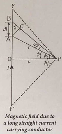
Let YY' be an infinitely long straight conductor carry current I. In order to calculate magnetic field at a point P which is at a distance a from the wire, let us consider a small line element dl (segment AB).
According to Biot Savart law, the magnetic field at a point P due to current element Idl is,
\({ d \vec B } =\frac { { \mu }_{ 0 } }{ 4\pi } \frac { { Idl sin \theta} }{ { r }^{ 2 } }\hat n \).
To apply trigonometry, draw a perpendicular AC to the line BP as shown in Figure.
In triangle ΔABC, \(\sin \theta=\frac{\mathrm{AC}}{\mathrm{AB}}\)
∴ AC = AB sinθ
\(\text { But, } A B =d l \Rightarrow A C=d l \sin \theta\)
Let dΦ be the angle subtended between AP and BP
ie., \(\angle \mathrm{APB}=\angle \mathrm{APC}=d \phi\)
In a triangle \(\triangle \mathrm{APC}, \sin (d \phi) \simeq A C / A P\)
Since, dΦ is very small, \(\sin (d \phi) \simeq d \phi\)
But, \(\mathrm{AP} =r \Rightarrow A C=r d \phi \)
\(\therefore \mathrm{AC} =d l \sin \theta=r d \phi \)
\(\therefore d \vec{B} =\frac{\mu_0}{4 \pi} \frac{I}{r^2}(r d \phi) \hat{n}=\frac{\mu_0}{4 \pi} \frac{I d \phi}{r} \hat{n}\)
Let Φ be the angle between AP and OP
\(\text {In a } \triangle \mathrm{OPA}, \cos \phi =\frac{\mathrm{OP}}{\mathrm{AP}}=\frac{\mathrm{a}}{\mathrm{r}} \)
\(r =\frac{a}{\cos \phi} \)
\(\text {Now, } d \vec{B} =\frac{\mu_0}{4 \pi} \frac{I}{a / \cos \phi} d \phi . \hat{n} \)
\(d \vec{B} =\frac{\mu_0 I}{4 \pi a} \cos \phi d \phi \hat{n}\)
The total magnetic field at P due to the conductor YY' is
\(\vec { B } = \int _{- \Phi _{ 1 } }^{ { \Phi }_{ 2} }d\vec B =\int _{ -\Phi _{ 1 } }^{ { \Phi }_{ 2 } }\frac { { \mu }_{ 0 }I }{ 4\pi a }{ cos\phi d\phi } \hat { n }\)
\(=\frac { { \mu }_{ 0 }I }{ 4\pi a }[{ sin\phi ]^{\phi_2} _{\phi_-1}} \hat { n }\)
\( \vec{B}=\frac { { \mu }_{ 0 }I }{ 4\pi a } (sin{ \Phi }_{ 1 }+sin{ \Phi }_{ 2 })\hat { n } \)
For infinitely long conductor, Φ1 = Φ2 = 90o
\(\therefore \vec{B}=\frac { { \mu }_{ 0 }I }{ 4\pi a } \times 2\hat{n}\Rightarrow\vec { B } =\frac { { \mu }_{ 0 }I }{ 2\pi a } \hat { n } \)
14.
There are three quantities required to specify the magnetic field of the Earth on its surface, which are often called as the elements of the Earth's magnetic field. They are:
(a) magnetic declination (D)
(b) magnetic dip or inclination (I)
(c) the horizontal component of the Earth's magnetic field (BH)
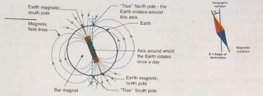
Let BE be the net Earth's magnetic field at any point P on the surface of the Earth. BE can be resolved into two perpendicular components.
Horizontal component, BH = BE cos I .... (1)
Vertical component, BV = BE sin I .....(2)
Dividing equation (1) and (2), we get,
\(=\frac{B_{V}}{B_{H}} ...(3)\)
(i) At magnetic equator:
The Earth's magnetic field is parallel to the surface of the Earth (i.e., horizontal) which implies that the needle of magnetic compass rests horizontally at an angle of dip, I = 0o Hence, BH = BE
BV = 0
This implies that the horizontal component is maximum and vertical component is zero at equator.
(ii) At magnetic poles:
The Earth's magnetic field is perpendicular to the surface of the Earth (i.e, vertical) which implies that the needle of magnetic compass rests vertically at an angle of dip, I = 90o
Hence, BH = 0
BV = BE
This implies that the vertical component is maximum at poles and horizontal component is zero at poles.
15.
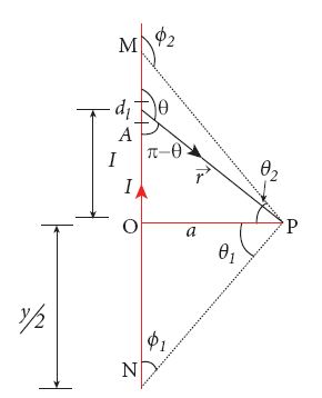
In a right angle triangle OPN let the angle \(\angle\)OPN = \(\theta \)1 which implies, \({ \varphi }_{ 1 }=\frac { \pi }{ 2 } -{ \theta }_{ 1 }\) and also in a right angle triangle OPM,
\(\angle\)OPN = \(\theta \)2 which implies, \({ \varphi }_{ 2 }=\frac { \pi }{ 2 } +{ \theta }_{ 2 }\)
Hence,
\(\overset { \rightarrow }{ B } =\frac { { \mu }_{ ° }I }{ 4\pi a } \left( cos\left( \frac { \pi }{ 2 } -{ \theta }_{ 1 } \right) -cos\left( \frac { \pi }{ 2 } +{ \theta }_{ 2 } \right) \right) \hat { n } \)
\(=\frac { { \mu }_{ ° }I }{ 4\pi a } (si{ n }_{ 1 }+{ sin }_{ 2 })\hat { n } \)
16.
i) Consider a bar magnet of length 2l and pole strength qm
ii) Force experienced by the magnet at each pole is qm B (equal) in opposite direction.
iii) So, magnet experiences a torque.
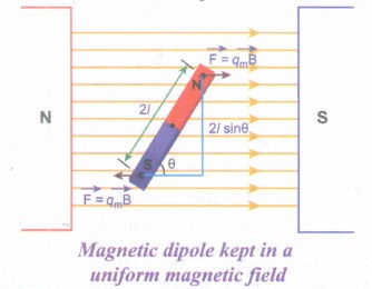
The force experienced by north pole,
\(\vec { { F }_{ N } } ={ q }_{ m }\vec { B } \)
The force experienced by south pole,
\(\vec { { F }_{ S } } =-{ q }_{ m }\vec { B } \)
∴ The net force acting on the dipole is,
\(\vec { F } =\vec { { F }_{ N } } +\vec { F_{ S } } =\vec { 0 } \)
The moment of force or torque experienced by north and south pole about point O is,
\(\vec { \tau } =\vec { ON } \times \vec { { F }_{ N } } +\vec { OS } \times \vec { { F }_{ S } } \)
\(\vec { \tau } =\vec { ON } \times { q }_{ m }\vec { B } +\vec { OS } \times (-{ q }_{ m }\vec { B } )\)
By using right hand cork screw rule, we conclude that the total torque is pointing into the paper. Since the magnitudes \(|\vec { ON } |=|\vec { OS } |=l\) and \(|{ q }_{ m }\vec { B } |=|-{ q }_{ m }\vec { B } |\).
The magnitudes of total torque about point O is
ፒ = l x qmB sinθ + l x qmB sinθ
ፒ = 2l x qmB sinθ
ፒ = pmB sinθ (∴ qm x 2l = pm)
In vector notation, \(\vec { \tau } =\vec { { p }_{ m } } \times \vec { B } \).

12th Standard Syllabus & Materials
12th Standard
TN 12th Computer Applications வலையமைப்பு வடமிடல் Sample Question Papers Study Material - QB365 Set A
NEW12th Standard
TN 12th Computer Applications களப்பெயர் முறைமை (DNS) Sample Question Papers Study Material - QB365 Set A
NEW12th Standard
TN 12th Computer Applications வலையமைப்பு எடுத்துக்காட்டுகள் மற்றும் நெறிமுறைகள் Sample Question Papers Study Material - QB365 Set A
NEW12th Standard
TN 12th Computer Applications கணினி வலையமைப்பு ஓர் அறிமுகம் Sample Question Papers Study Material - QB365 Set A



Tamilnadu Stateboard 12th Standard Subjects

Maths

Chemistry
Physics

Biology

Computer Science

Business Maths and Statistics

Economics

Commerce

Accountancy

History

Computer Applications
Biology
Computer Technology
Computer Applications
Computer Science
Business Maths and Statistics
Commerce
Economics
Maths
Chemistry
Physics
Computer Technology
History
Accountancy

Tamil

English

French
Tamilnadu Stateboard Standards

