
 100% FREE ACCESS
12th Standard Syllabus & Materials
12th Standard
TN 12th Computer Applications மின்னணு தரவு பரிமாற்றம் Sample Question Papers Study Material - QB365 Set A
NEW12th Standard
TN 12th Computer Applications மின் - வணிக பாதுகாப்பு அமைப்புகள் Sample Question Papers Study Material - QB365 Set A
NEW12th Standard
TN 12th Computer Applications மின்னணு செலுத்தல் முறைகள் Sample Question Papers Study Material - QB365 Set A
NEW12th Standard
TN 12th Computer Applications மின் - வணிகம் Sample Question Papers Study Material - QB365 Set A
NEW12th Standard
TN 12th Computer Applications திறந்த மூல கருத்துருக்கள் Sample Question Papers Study Material - QB365 Set A
NEW12th Standard
TN 12th Computer Applications வலையமைப்பு வடமிடல் Sample Question Papers Study Material - QB365 Set A

Published on: 02/09/2020
12th Standard Physics English Medium Model 3 Mark Book Back Questions (New Syllabus) 2020
Download Tamil Nadu 12th Standard Physics question papers, model tests, one-mark questions, important questions, and public exam papers in PDF format. Free study materials and answer keys for TN State Board students.
Questions + Answers key
Take MCQ Physics Test1.
Explain why photoelectric effect cannot be explained on the basis of wave nature of light.
2.
The Bohr atom model is derived with the assumption that the nucleus of the atom is stationary and only electrons revolve around the nucleus. Suppose the nucleus is also in motion, then calculate the energy of this new system.
3.
Explain the idea of carbon dating.
4.
Obtain the expression for energy stored in the parallel plate capacitor.
5.
A coil of a tangent galvanometer of diameter 0.24 m has 100 turns. If the horizontal component of Earth’s magnetic field is 25 x 10–6 T then, calculate the current which gives a deflection of 60o .
6.
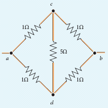
Five resistors are connected in the configuration as shown in the figure. Calculate the equivalent resistance between the points a and b.
7.
Calculate the electrostatic force and gravitational force between the proton and the electron in a hydrogen atom. They are separated by a distance of 5.3 x 10⁻¹¹ m. The magnitude of charges on the electron and proton are 1.6 x 10⁻¹⁹ C. Mass of the electron is me = 9.1 x 10⁻³¹ kg and mass of proton is mp = 1.6 x 10⁻²⁷ kg.
8.
In a transistor connected in the common base configuration, \(\alpha\) = 0 95, IE = 1 mA. Calculate the values of IC and IB.
9.
A monochromatic light is incident on an equilateral prism at an angle 30o and is emergent at an angle of 75o . What is the angle of deviation produced by the prism?
10.
Light travelling through transparent oil enters in to glass of refractive index 1.5. If the refractive index of glass with respect to the oil is 1.25, what is the refractive index of the oil?
11.
The relative magnetic permeability of the medium is 2.5 and the relative electrical permittivity of the medium is 2.25. Compute the refractive index of the medium.
12.
The current flowing in the first coil changes from 2 A to 10 A in 0.4 s. Find the mutual inductance between two coils if an emf of 60 mV is induced in the second coil. Also determine the magnitude of induced emf in the second coil if the current in the first coil is changed from 4 A to 16 A in 0.03 s. Consider only the magnitude of induced emf.
13.
A closed coil of 40 turns and of area 200 cm2, is rotated in a magnetic field of flux density 2 Wb m–2. It rotates from a position where its plane makes an angle of 30o with the field to a position perpendicular to the field in a time 0.2 s. Find the magnitude of the emf induced in the coil due to its rotation.
14.
Let the magnetic moment of a bar magnet be \(\overset { \rightarrow }{ { p }_{ m } } \) whose magnetic length is d = 2l and pole strength is qm. Compute the magnetic moment of the bar magnet when it is cut into two pieces
(a) along its length
(b) perpendicular to its length.
15.
A potential difference across 24 Ω resistor is 12 V. What is the current through the resistor?
16.
Describe briefly Davisson – Germer experiment which demonstrated the wave nature of electrons.
17.
What are the possible harmful effects of usage of Nanoparticles? Why?
18.
State Boolean laws. Elucidate how they are used to simplify Boolean expressions with suitable example.
19.
Explain the construction and working of a full wave rectifier
20.
Discuss about the simple microscope and obtain the equations for magnification for near point focusing and normal focusing.
21.
Obtain lens maker’s formula and mention its significance.
22.
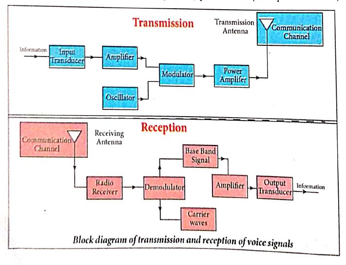
Explain the basic elements of communication system with the necessary block diagram.
23.
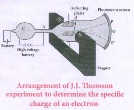
Explain the J.J. Thomson experiment to determine the specific charge of electron.
24.
Explain the principle and working of a moving coil galvanometer.
25.
Deduce the relation for the magnetic field at a point due to an infinitely long straight conductor carrying current using Biot-Savart law.
26.
How are the three different emfs generated in a three-phase AC generator? Show the graphical representation of these three emfs.
27.
Define self-inductance of a coil interms of
(i) magnetic flux and
(ii) induced emf.
28.
Explain the types of emission spectrum.
29.
Calculate the electric field due to a dipole on its axial line and equatorial plane.
30.
Explain the determination of unknown resistance using meter bridge.
1.
From Maxwell's theory we learnt that light is an electromagnetic wave consisting of coupled electric and magnetic oscillations that move with the speed of light and exhibit typical wave behaviour. Let us try to explain the experimental observations of photoelectric effect using wave picture of light.
(i) When light is incident on the target, there is a continuous supply of energy to the electrons in the metal surface.
(ii) According to wave theory, light of greater intensity should impart greater kinetic energy to the liberated electrons (Here, intensity of light is the energy delivered per unit area per unit time). But this does not happen. The experiments show that maximum kinetic energy of the photoelectrons does not depend on the intensity of the incident light.
(iii) According to wave theory, if a sufficiently intense beam of light is incident on the surface, electrons will be liberated from the surface of the target, however low the frequency of the radiation is. From the experiments, we know that photoelectric emission is not possible below a certain minimum frequency. Therefore, the wave theory fails to explain the existence of threshold frequency.
(iv) Since the energy of light is spread across the wavefront, the electrons which receive energy from it are large in number. Each electron needs considerable amount time (a few hours) to get energy sufficient to overcome the work function and to get liberated from the surface. But experiments show that photoelectric emission is almost instantaneous process (the time lag is less than 10-9 s after the surface is illuminated) which could not be explained by wave theory.
Thus, the experimental observations of photoelectric emission could not be explained on the basis of the wave theory of light.
2.
Let the mass of the electron be m and mass of the nucleus be M. Since there is no external force acting on the system, the centre of mass of hydrogen atom remains at rest. Hence, both nucleus and electron move about the centre of mass as shown in figure.
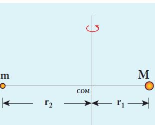
Let V be the velocity of the nuclear motion and υ be the velocity of electron motion. Since the total linear momentum of the system is zero,
−mሀ + Mሀ = 0 or
Mሀ = mሀ = p
\(\vec { { p }_{ e } } +\vec { { p }_{ n } } =\vec { 0 } \) or
\(|\vec { { p }_{ e } } |=|\vec { { p }_{ n } } |=p\)
Hence, the kinetic energy of the system is
KE = \(\frac { { { p }^{ 2 } }_{ n } }{ 2M } +\frac { { { p }^{ 2 } }_{ e } }{ 2m } =\frac { { p }^{ 2 } }{ 2 } \left( \frac { 1 }{ M } +\frac { 1 }{ m } \right) \)
Let \(\frac { 1 }{ M } +\frac { 1 }{ m } =\frac { 1 }{ { \mu }_{ m } } \). Here the reduced mass is
\({ \mu }_{ m }=\frac { mM }{ M+m } \)
Therefore, the kinetic energy of the system now is
\(KE=\frac { { p }^{ 2 } }{ { 2\mu }_{ m } } \)
Since the potential energy of the system is same, the total energy of the hydrogen can be expressed by replacing mass by reduced mass, which is
\({ E }_{ n }=-\frac { { \mu }_{ m }{ e }_{ 4 } }{ 8{ \epsilon ^{ 2 } }_{ 0 }{ h }^{ 2 } } \frac { 1 }{ { n }^{ 2 } } \)
Since the nucleus is very heavy compared to the electron, the reduced mass is closer to the mass of the electron.
3.
(i) The application of beta decay is radioactive dating or carbon dating.
(ii) Using this technique, the age of an ancient object can be calculated.
(iii) All living organisms absorb carbon dioxide (CO2) from air to synthesize organic molecules.
(iv) In this absorbed CO2, the major part is \(_{ 6 }^{ 12 }{ C }\) and very small fraction (1.3 x 10⁻¹²) is radioactive \(_{ 6 }^{ 14 }{ C }\)whose half-life is 5730 years
(v) Carbon-14 in the atmosphere is always decaying but at the same time, cosmic rays from outer space are continuously bombarding the atoms in the atmosphere which produces \(_{ 6 }^{ 14 }{ C }\)
(v) So the Continuous production and decay of \(_{ 6 }^{ 14 }{ C }\) in the atmosphere keep the ratio of \(_{ 6 }^{ 14 }{ C }\) always constant.
(vi) Since our human body, tree or any living organism continuously absorbs CO2 from the atmosphere, the ratio of \(_{ 6 }^{ 14 }{ C }\) to \(_{ 6 }^{ 12 }{ C }\) in the living organism is also nearly constant.
(vii) But when the organism get dies, it stops absorbing CO2
(viii) Now \(_{ 6 }^{ 14 }{ C }\) starts to decay, the ratio of \(_{ 6 }^{ 14 }{ C }\) to \(_{ 6 }^{ 12 }{ C }\) in a dead organism or specimen decreases over the years.
(ix) Suppose the ratio of \(_{ 6 }^{ 14 }{ C }\) to \(_{ 6 }^{ 12 }{ C }\) in the ancient tree pieces excavated is known, then the age of the tree pieces can be calculated.
4.
Energy stored in the capacitor
i) Capacitor not only stores the charge but also it stores energy. When a battery is connected to the capacitor, electrons of total charge - Q are transferred from one plate to the other plate. To transfer the charge, work is done by the battery. This work done is stored as electrostatic potential energy in the capacitor.
ii) To transfer an infinitesimal charge dQ for a potential difference V, the work done is given by
dW = V dQ
Where \(V=\frac { Q }{ C } \) .....(1)
iii) The total work done to charge a capacitor is
\(W=\int _{ 0 }^{ Q }{ \frac { Q }{ C } } dQ=\frac { { Q }^{ 2 } }{ 2C } \quad \quad ....(2)\)
This work done is stored as electrostatic potential energy (UE) in the capacitor.
\({ U }_{ E }=\frac { { Q }^{ 2 } }{ 2C } =\frac { 1 }{ 2 } { CV }^{ 2 },\quad (\therefore Q=CV)\quad ....(3)\)
(iv) This stored energy is thus directly proportional to the capacitance of the capacitor and the square of the voltage between the plates of the capacitor.Substituting \(C=\frac { { \varepsilon }_{ 0 }A }{ d } \) and V = Ed.
\(U=\frac { 1 }{ 2 } \left( \frac { { \varepsilon }_{ 0 }A }{ d } \right) { (Ed) }^{ 2 }=\frac { 1 }{ 2 } { \varepsilon }_{ 0 }(Ad){ E }^{ 2 }\quad \quad \quad \quad \quad ...(4)\)
where Ad = volume of the space between the capacitor plates. The energy stored per unit volume of space is defined as energy density \({ u }_{ E }=\frac { U }{ Volume } \)
Equation (4) ⇒ \({ u }_{ E }=\frac{1}{2}{ \varepsilon }_{ 0 }{ E }^{ 2 }\).....(5)
(v) From equation (5),
(a) We infer that the energy is stored in the electric field existing between the plates of the capacitor. Once the capacitor is allowed to discharge, the energy is retrieved.
(b) The energy density depends only on the electric field and not on the size of the plates of the capacitor.
(c) This is true for the electric field due to any type of charge configuration.
5.
The diameter of the coil is 0.24 m. Therefore, radius of the coil is 0.12 m.
Number of turns is 100 turns. Earth’s magnetic field is 25 x 10-6 T
Deflection is
\(\theta =60°\Rightarrow tan60°=\sqrt { 3 } =1.732\)
\(I=\frac { 2R{ B }_{ H } }{ { \mu }_{ ° }N } tan\theta \)
\(=\frac { 2\times 0.12\times 25\times 1{ 0 }^{ -6 } }{ 4\times 1{ 0 }^{ -7 }\times 3.14\times 100 } \times 1.732=0.82\times 1{ 0 }^{ -1 }A\)
I = 0.082 A
6.
Case (a)
To find the equivalent resistance between the points a and b, we assume that current is entering the junction at a. Since all the resistances in the outside loop are the same (1Ω), the current in the branches ac and ad must be equal. Hence the points C and D are at the same potential and no current through 5 Ω. It implies that the 5 Ω has no role in determining the equivalent resistance and it can be removed. So the circuit is simplified as shown in the figure.
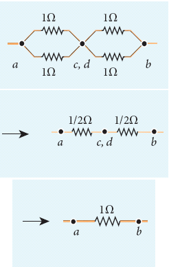
The equivalent resistance of the circuit between a and b is Req = 1Ω
7.
The proton and the electron attract each other. The magnitude of the electrostatic force between these two particles is given by
\(F_e=\frac { ke^{ 2 } }{ { r }^{ 2 } } =\frac { 9\times 10^{ 9 }\times (1.6\times 10^{ -19 })^{ 2 } }{ (5.3\times 10^{ -11 })^{ 2 } } \)
=\(\frac { 9\times 2.56 }{ 28.09 } \) x 10-7 = 8.2 x 10⁻⁸ N
The gravitational force between the proton and the electron is attractive. The magnitude of the gravitational force between these particles is
FG = \(\frac { G{ m }_{ e }{ m }_{ p } }{ { r }^{ 2 } } \)
= \(\frac { 6.67\times 10^{ -11 }\times 9.1\times 10^{ -31 }\times 1.6\times 10^{ -27 } }{ (5.3\times 10^{ -11 })^{ 2 } } \)
= \(\frac { 97.11 }{ 28.09 } \) x 10-47 = 3.4 x 10-47N
The ratio of the two forces \(\frac { { F }_{ e } }{ F_{ G } } =\frac { 8.2\times 10^{ -8 } }{ 3.4\times 10^{ -47 } } \)
= 2.41 x 1039
Note that Fe ≈ 1039 FG
The electrostatic force between a proton and an electron is enormously greater than the gravitational force between them. Thus the gravitational force is negligible when compared with the electrostatic force in many situations such as for small size objects and in the atomic domain. This is the reason why a charged comb attracts an uncharged piece of paper with greater force even though the piece of paper is attracted downward by the Earth. This given figure is shown in below.

Electrostatic attraction between a comb and pieces of papers
8.
α = \(\frac{I_C}{I_E}\)
IC = α IE = 0.95 x 1 = 0.95 mA
IE = IB + IC
∴ IB = IE - IC = 1 - 0.95 = 0.05 mA
9.
Since, the prism is equilateral, A = 60o;
Given, i1 = 30o;i2 = 75o
Equation for angle of deviation, d = i1 + i2 – A
Substituting the values, d = 30°+ 75°– 60°= 45°
The angle of deviation produced d = 45o
10.
Given, ngo = 1.25 and ng = 1.5
Refractive index of glass with respect to oil,
\({ n }_{ go }=\cfrac { { n }_{ g } }{ { n }_{ 0 } } \)
Rewriting for refractive index of oil,
\({ n }_{ p }=\cfrac { { n }_{ g } }{ { n }_{ go } } =\cfrac { 1.5 }{ 1.25 } =1.2\)
The refractive index of oil is, no = 1.2
11.
Dielectric constant (relative permittivity of the medium) is εr = 2.25
Magnetic permeability is μr = 2.5
Refractive index of the medium,
n = \(\sqrt { { \varepsilon }_{ r }{ \mu }_{ r } } =\sqrt { 2.25\times 2.5 } \) = 2.37
12.
Case (i):
di1 = 10 – 2 = 8 A; dt = 0.4 s;
ε2 = 60 x 10-3V
Case(ii):
di1 = 16 – 4 = 12 A; dt = 0.03 s
(i) Mutual inductance between the coils.
\({ M }=\frac { { \epsilon }_{ 2 } }{ \frac { { di }_{ 1 } }{ dt } } \)
\(=\frac { 60\times { 10 }^{ -3 }\times 0.4 }{ 8 } \)
\({ M }=3\times { 10 }^{ -3 }H\)
(ii) Induced emf in the second coil due to the rate of change of current in the first coil is
\({ \epsilon }_{ 2 }={ M }=\frac { { di }_{ 1 } }{ dt } \)
\(=\frac { 3\times { 10 }^{ -3 }\times 12 }{ 0.03 } \)
ε2 = 1.2V
13.
N = 40 turns; B = 2 Wb m-2
A = 200 cm2 = 200 x 10-4 m2;
Initial flux, \(\Phi_i\) = BA cos\(\theta\)
= 2 x 200 x 10-4 x cos60o
since θ = 90°− 30°= 60°
\(\Phi_i\)= 2 x 10⁻² Wb
Final flux, \(\Phi_f\) = BA cos\(\theta\)
= 2 x 200 x 10-4 x cos0o since \(\theta\) = 0o
\(\Phi_f\) = 4 x 10⁻²Wb
Magnitude of the induced emf is
\(ε =N\frac { d{ \Phi }_{ B } }{ dt } \)
\(=\frac { 40\times (4\times { 10 }^{ -2 }-2\times { 10 }^{ -2 }) }{ 0.2 } =4V\)
14.
(a) a bar magnet cut into two pieces along its length:
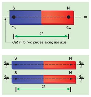
When the bar magnet is cut along the axis into two pieces, new magnetic pole strength is \({ q }_{ m }^{ ' }=\frac { { q }_{ m } }{ 2 } \) but magnetic length does not change. So, the magnetic moment is
\({ p }_{ m }^{ ' }={ q' }_{ m }2l\)
\({ p }_{ m }^{ ' }=\frac { { q }_{ m } }{ 2 } 2l=\frac { 1 }{ 2 } ({ q }_{ m }2l)=\frac { 1 }{ 2 }p_ m\)
In vector notation, \(\vec{p}'_m=\frac{1}{2}\vec{p}_m\)
(b) a bar magnet cut into two pieces perpendicular to the axis:
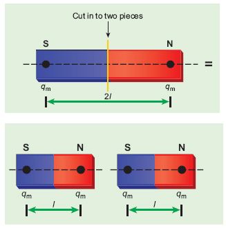
When the bar magnet is cut perpendicular to the axis into two pieces, magnetic pole strength will not change but magnetic length will be halved. So the magnetic moment is
\({ p }_{ m }^{ ' }={ q }_{ m }\times \frac { 1 }{ 2 } (2l)=\frac { 1 }{ 2 } ({ q }_{ m }.2l)=\frac { 1 }{ 2 } { p }_{ m }\)
In vector notation, \(\vec{p}'_m=\frac{1}{2}\vec{p}_m\)
15.
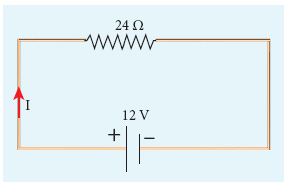
V = 12 V and R = 24 Ω
Current, I = ?
From Ohm’s law, \(I=\frac{V}{R}=\frac{12}{24}=0.5A\)
16.
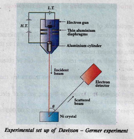
Davisson - Germer experiment
(i) The filament F is heated by a low tension (L . T) battery. Electrons are emitted from the hot filament by thermionic emission.
(ii) They are then accelerated due to the potential diference between the filament and the anode aluminum cylinder by a high tension (H.T) battery.
(iii) Electron beam is collimated by using two thin aluminum diaphragms and is allowed to strike a single crystal of Nickel.
(iv) The electrons scattered by Niatoms in diflerent directions are received by the electron detector which measures the intensity of scattered electron beam.
(v) The detector is capable of rotation in the plane of the paper, so that the angle (\(\theta\)) between the incident beam and the scattered beam can be changed at our will.
(vi) The intensity of the scattered electron beam is measured as a function of the angle \(\theta\).
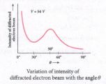
(i) Figure shows the variation of intensity of the scattered electrons with the angle \(\theta\) for the accelerating voltage of 54 V.
(ii) For a given accelerating voltage V, the scattered wave shows a peak or maximum at an angle of 50o to the incident electron beam.
(iii) This peak in intensity is attributed to the constructive interference of electrons diffracted from various atomic layers of the target material.
(iv) From the known value of interplanar spacing of Nickel, the wavelength of the electron wave has been experimentally calculated as 1.65\(\overset { o }{ A }\).
(v) The wavelength can also be calculated from de Broglie relation for V = 54 V from equation as
\(\lambda =\cfrac { 12.27 }{ \sqrt { V } } \overset { o }{ A } =\cfrac { 12.27 }{ \sqrt { 54 } } \)
\(\lambda =1.67\overset { o }{ A } \)
(vi) This value agrees very well with the experimentally observed wavelength of 1.65 \(\overset { o }{ A }\). Thus this experiment directly verifies de Broglie's hypothesis of the wave nature of moving particles.
17.
Possible harmful effects of nanoparticles:
(i) They may easily get absorbed onto the surface of living organisms as dimensions of the nano particles are the same as that of biological molecules such as proteins.
(ii) They readily enter the tissues and fluids of the body and distort their functions
(iii) Nano particles can also cross cell membranes so that, interaction with living systems is affected
(iv) It is also possible for the inhaled nanoparticles to reach the blood, to reach other sites such as the liver, heart or blood cells.
18.
Laws of Boolean algebra:
Complement law:
| A | Y=Ā |
| 0 | Y = \(\bar { 0 } \) = 1 |
| 0 | Y=\(\bar { 1 } \)=0 |
The complement law can be realised as Ā = A
OR laws:
| A | B | Y=A+B |
| 0 | 0 | Y = 0 + 0 = 0 |
| 0 | 1 | Y = 0 + 1 = 1 |
| 1 | 0 | Y = 1 + 0 = 1 |
| 1 | 1 | Y = 1 + 1 = 1 |
The OR laws can be realised as:
| 1st law | A+0=A |
| 2st law | A+1=1 |
| 3st law | A+A=A |
| 4st law | A+Ā=1 |
AND law:
| A | B | Y=A.B |
| 0 | 0 | Y=0.0=0 |
| 0 | 1 | Y=0.1=0 |
| 1 | 0 | Y=1.0=0 |
| 1 | 1 | Y=1.1=1 |
The AND laws can be realised as:
| 1st law | A.0=0 |
| 2st law | A.1=A |
| 3st law | A.A=A |
| 4st law | A.Ā=0 |
The Boolean operations obey the folloWing laws:
Communtative laws:
A+B =B+A
A.B =B.A
A sociate laws:
A + (B + C) = (A + B) + C
A. (B.C) = (A.B).C
D stributive laws:
A (B + C) = AB + BC
A + BC = (A + B) (A + C)
The above laws are used to simplify complicated expressions and to simplify the logic circuitry.
19.
FuIl wave rectifier :
The positive and negative half cycles of the AC input signal pass through the full wave rectifier circuit and hence it is called the full wave rectifier
Construction:
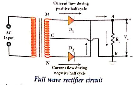
(i) It consists of two p-n junction diodes, a center-tapped transformer, and a load resistor (R1)
(ii) The centre is usually taken as the ground or zero voltage reference point.
(iii) Due to the centre tap transformer, the output voltage rectified by each diode is only one-half of the total secondary voltage.
Working:
During positive half cycle :
(i) When the positive half cycle of the ac input signal passes through the circuit, terminal M is positive, G is at zero potential and N is at negative potential.
(ii) This forward biases diode D1 and reverse biases diode D2.
(iii) Hence, being forward biased, diode D1 conducts and current flows along the path MD1AGC.
During negative half cycle:
(i) When the negative half cycle of the AC input signal passes through the circuit, terminal N becomes positive, C is at zero potential and M is at negative potential.
(ii) This forward biases diode D2 and reverse biases diode D1.
(iii) Hence, being forward biased, diode D2 conducts and current flows along the path ND2BGC.
(iii) During both positive and negative half cycles of the input signal, the current flows through the load in same direction.
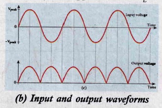
(iv) The output signal corresponding to the input signal is shown in Figure. Though both half cycles of AC input are rectified, the output is still pulsating in nature.
(v) The efficiency (η) of full wave rectifier is twice that of a half wave rectifier and is found to be 81.2 %.
20.
(i) A simple microscope is a single magnifying (converging) lens of small focal length. To get an erect, magnified and virtual image of the object.
(ii) For this the object is placed between the focal length Fand P on one side of the lens and viewed from other side of the lens. There are two magnifications to be discussed for two kinds of focusing.
(a) Near point focusing:
The eye is least strained when image is formed at near point,i.e. 25 cm. The near point is also called as least distance of distinct vision. This is shown in Figure.
.JPG)
Magnification in near point focusing:
(i) Object distance u is less than f
(ii) The image distance is the near point D. The magnification m is given by the relation,
\(m=\cfrac { v }{ u } \) ...............(1)
Substituting, V = - D and u= - u, as both the distances are measured to the left of the lens. Hence,
\(m=\cfrac { -D }{ -u }\)
\(m=\cfrac { D }{ u } \) ...............(2)
Using lens equation, W.K.T, m = 1 - (v/f)
Substiuting v = -D gives, \(\\ m=1+\cfrac { D }{ f } \) ..................(3)
This is the magnification for near point focusing.
(b) Normal focusing :
(i) The eye is most relaxed when the image is formed at infinity. The focusing is called normal focusing when the image is formed at infinity. This is shown in Figure (b).
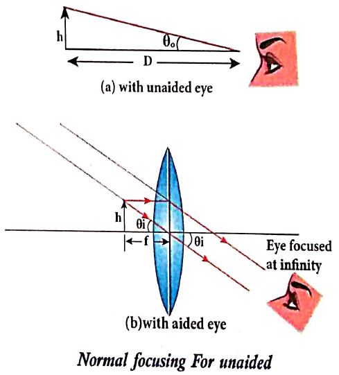
Magnification in normal focusing (angular magnification):
(ii) The angular magnification is defined as the ratio of angle θ1 subtended by the image with aided eye to the angle θ0 subtended by the object with unaided eye.
\(m=\cfrac { { \theta }_{ 1 } }{ { \theta }_{ 0 } } \) .........(2)
For unaided eye shown in Figure (a),
\(tan\theta _{ 0 }\approx { \theta }_{ 1 }=\cfrac { h }{ D } \) ................(3)
For aided eye shown in Figure(b).
\(tan\theta _{ i }={ \theta }_{ i }=\cfrac { h }{ f } \) ...................(4)
The angular magnification is,
\(m=\cfrac { { \theta }_{ i } }{ { \theta }_{ o } } =\cfrac { h/f }{ h/D } \)
\(m=\cfrac { D }{ f } \) ..............(5)
This is the magnification for normal focusing.
21.
(i) Let us consider a thin lens made up of a medium of refractive index n2 is placed in a medium of refractive index n1. Let R1 and R2 be the radii of curvature of two spherical surfaces (1) and (2) respectively and P be the pole.
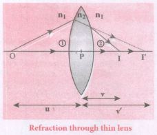
(ii) Consider a point object 'O' on the principal axis. A paraxial ray from 'O' which falls very close to P, after refraction at the surface (1) forms image at 1'.
(iii) Before it does so, it is again refracted by the surface (2). Therefore the final image is formed at I.
(iv) The general equation for the refraction at a single spherical surface is given from Equation,
\(\cfrac { { n }_{ 2 } }{ v } -\cfrac { { n }_{ 1 } }{ v} =\cfrac { \left( { n }_{ 2 }-{ n }_{ 1 } \right) }{ { R } } \)
For the refracting surface (1), the light goes from n1 to n2
\(\cfrac { { n }_{ 2 } }{ v' } -\cfrac { { n }_{ 1 } }{ u } =\cfrac { \left( { n }_{ 2 }-{ n }_{ 1 } \right) }{ { R }_{ 1 } } \) .....(1)
For the refracting surface (2), the light goes from n2 to n1
\(\frac{n_{1}}{v}+\frac{n_{2}}{v^{\prime}}=\frac{\left(n_{1}-n_{2}\right)}{R_{2}}\) ......(2)
For surface (2) I' acts as virtual object.
Adding the above two equations (1) and (2)
\(\cfrac { { n }_{ 1 } }{ v } -\cfrac { { n }_{ 1 } }{ u } =\left( { n }_{ 2 }-{ n }_{ 1 } \right) \left( \cfrac { 1 }{ { R }_{ 1 } } -\cfrac { 1 }{ { R }_{ 2 } } \right) \)
on further simplifying and rearranging,
\(\cfrac { 1 }{ v } -\cfrac { 1 }{ u } =\left( \cfrac { { n }_{ 2 }-{ n }_{ 1 } }{ { n }_{ 1 } } \right) \left( \cfrac { 1 }{ { R }_{ 1 } } -\cfrac { 1 }{ { R }_{ 2 } } \right) \)
\(\cfrac { 1 }{ v } -\cfrac { 1 }{ u } =\left( \cfrac { { n }_{ 2 } }{ n_{ 1 } } -1 \right) \left( \cfrac { 1 }{ { R }_{ 1 } } -\cfrac { 1 }{ { R }_{ 2 } } \right) \) ....(3)
If the object is at infinity, the image is formed at the focus of the lens. Thus, for u = \(\infty\), v = f. Then the equation becomes.
\(\cfrac { 1 }{ f } -\cfrac { 1 }{ \infty } =\left( \cfrac { { n }_{ 2 } }{ { { n }_{ 1 } } } -1 \right) \left( \cfrac { 1 }{ { R }_{ 1 } } -\cfrac { 1 }{ { R }_{ 2 } } \right) \)
\(\cfrac { 1 }{ f } =\left( \cfrac { { n }_{ 2 } }{ { n }_{ 1 } } -1 \right) \left( \cfrac { 1 }{ { R }_{ 1 } } -\cfrac { 1 }{ { R }_{ 2 } } \right) \) ......(4)
If the lens is kept in air, then we can take n2 = n and n1 = 1. So the equation (4) becomes,
\(\\ \cfrac { 1 }{ f } =\left( n-1 \right) \left( \cfrac { 1 }{ { R }_{ 1 } } -\cfrac { 1 }{ { R }_{ 2 } } \right) \) ..(5)
The above equation is called the lens maker's formula.
Significance:
It tells the lens manufacturers what curvature is needed to make a lens of desired focal length with a material of particular refractive index to make a lens of desired focal length. This formula holds good also for a concave lens.
22.
a) Information (Baseband or input signal):
i) Information can be in the form of a sound signal like speech, music, pictures, or computer data which is given as input to the input transducer.
b) Input transducer:
i) It converts the information which is in the form of sound, music, pictures or computer data into corresponding electrical signals.
ii) The electrical equivalent of the original information is called the baseband signal.
iii) The best example is the microphone that converts sound energy into electrical energy.
c) Transmitter
i) It feeds the electrical signal from the transducer to the communication channel
ii) It consists of circuits such as amplifier, oscillator, modulator, and power amplifier.
iii) Amplifier: The transducer output is very weak and is amplified by the amplifier.
iv) Oscillator: It generates high-frequency carrier wave (a sinusoidal wave) for long distance transmission into space. As the energy of a wave is proportional to its frequency, the carrier wave has very high energy.
v) Modulator: It superimposes the baseband signal onto the carrier signal and generates the modulated signal.
vi) Power amplifier: It increases the power level of the electrical signal in order to cover a large distance.
d) Transmitting antenna:
i) It radiates the radio signal into space in all directions.
ii) It travels in the form of electromagnetic waves with the speed of light.
e) Communication channel:
Communication channel is used to carry the electrical signal from transmitter to receiver with less noise or distortion.
Example: Wires, cables, optical fibres in wireline communication and free space in wireless communication.
f) Receiver:
i) The signals that are transmitted through the communication medium are received with the help of a receiving antenna and are fed into the receiver.
ii) The receiver consists of electronic circuits like demodulator, amplifier, detector etc. The demodulator extracts the baseband signal from the carrier signal.
iii) Then the baseband signal is detected and amplified using amplifiers.
iv) Finally, it is fed to the output transducer.
g) Repeaters:
i) Repeaters are used to increase the range or distance through which the signals are sent.
ii) It is a combination of transmitter and receiver.
iii) The signals are received, amplified, and retransmitted with a carrier signal of different frequency to the destination.
iv) The best example is the communication satellite in space
h) Output transducer:
i) It converts the electrical signal back to its original form such as sound, music, pictures or data.
ii) Examples of output transducers are loudspeakers, picture tubes, computer monitor, etc
23.
Principle:
Cathode rays are deflected in electric and magnetic fields.
By the variation of electric and magnetic fields, mass normalized charge or the specific charge (charge per unit mass) of the cathode rays is measured.
Construction and Working:
(i) Cathode rays (electron beam) produced at cathode of a highly evacuated discharge tube. Cathode rays are attracted towards anode disc A.
(ii) Pin hole in the anode disc allows only a narrow beam of cathode rays.
(iii) These cathode rays are now allowed to pass through the parallel metal plates, maintained at high voltage.
(iv) Further, discharge tube is kept in between pole pieces of magnet.
(v) Electric and magnetic fields are perpendicular to each other.
(vi) When the cathode rays strike the zinc sulphide coated screen (O), produces scintillation and hence bright spot is observed.
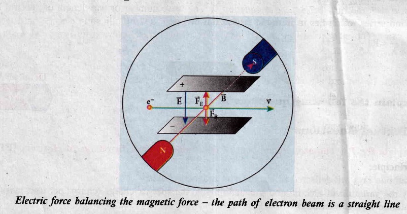
(i) Determination of velocity of cathode rays:
(a) For a fixed electric field between the plates, the magnetic field is adjusted such that the cathode rays (electron beam) strike at the original position O.
(b) This means that the magnitude of electric force is balanced by the magnitude of force due to magnetic field.
(ie) Ee = Bev
\(\Rightarrow v=\frac { E }{ B } \) ...(1)
(ii) Determination of specific charge:
(a) Since accelerated from cathode to anode, the potential energy of the electron beam at the cathode is converted into kinetic energy of the electron beam at the anode.
(b) Let V be the potential difference between anode and cathode, then the potential energy is eV.
Then from law of conservation of energy,
\(eV=\frac { 1 }{ 2 } { mv }^{ 2 } \)
\(\frac { e }{ m } =\frac { { v }^{ 2 } }{ 2V } \) ....(2)
Substituting (1) in (2),
\(\frac { e }{ m } =\frac { 1 }{ 2V } \frac { { E }^{ 2 } }{ { B }^{ 2 } } \)
By substituting known values, we get
\(\frac { e }{ m } =1.7\times { 10 }^{ 11 }{ CKg }^{ -1 }\)
The specific charge \(\frac{\mathrm{e}}{\mathrm{m}}\) is independent of (a) gas used (b) nature of the electrodes
24.
Principle : When a current carrying loop is placed in a uniform magnetic field it experiences a torque.
Construction : A moving coil galvanometer consists of a rectangular coil PQRS of insulated thin copper wire. The coil contains a large number of turns wound over a light metallic frame. A cylindrical soft-iron core is placed symmetrically inside the coil as shown in Figure. The rectangular coil is suspended freely between two pole pieces of a horse-shoe magnet.
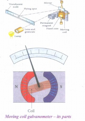
The upper end of the rectangular coil is attached to one end of fine strip of phosphor bronze and the lower end of the coil is connected to a hair spring which is also made up of phosphor bronze. In a fine suspension strip, a small plane mirror is attached in order to measure the deflection of the coil with the help of lamp and scale arrangement. The other end of the mirror is connected to a torsion head. In order to pass electric current through the galvanometer, the suspension strip and the spring S are connected to terminals.
Working : Consider a single turn of the rectangular coil PQRS whose length be l and breadth b. PQ = RS = l and QR = SP = b.
Let I be the electric current flowing through the rectangular coil PQRS as shown in Figure. The horse-shoe magnet has hemi - spherical magnetic poles which produces a radial magnetic field. Due to this radial field, the sides QR and SP are always parallel to the magnetic field B and experience no force. The sides PQ and RS are always parallel to the magnetic field and experience force in opposite directions. Due to this, torque is produced.
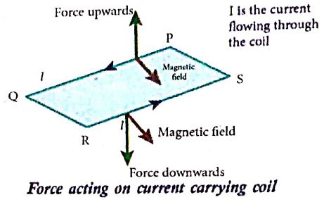
For single turn, the deflection torque is,
て = bF = bBIl = (lb)BI
て = ABI
since, area of the coil A = lb
For coil with N turns, we get
て = NABI ........(1)
Due to this deflecting torque, the coil gets twisted and restoring torque (also known as restoring couple) is developed. Hence the moment of restoring couple is proportional to the amount of twist θ. Thus
て = Kθ ............(2)
where K is the restoring couple per unit twist or torsional constant of the spring.
At equilibrium, the deflection couple is equal to the restoring couple. Therefore by comparing equations (1) and (2), we get,
NABI = Kθ
⇒ I =\(\frac { K }{ NAB } \) θ ...........(3)
(or) I = Gθ
where G = \(\frac { K }{ NAB } \) is called galvanometer constant or current reduction factor of the galvanometer.
Since, suspended moving coil galvanometer is very sensitive, we have to handle with high care while doing experiments. Most of the galvanometer we use are pointer type moving coil galvanometer.
25.
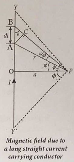
Let YY' be an infinitely long straight conductor carry current I. In order to calculate magnetic field at a point P which is at a distance a from the wire, let us consider a small line element dl (segment AB).
According to Biot Savart law, the magnetic field at a point P due to current element Idl is,
\({ d \vec B } =\frac { { \mu }_{ 0 } }{ 4\pi } \frac { { Idl sin \theta} }{ { r }^{ 2 } }\hat n \).
To apply trigonometry, draw a perpendicular AC to the line BP as shown in Figure.
In triangle ΔABC, \(\sin \theta=\frac{\mathrm{AC}}{\mathrm{AB}}\)
∴ AC = AB sinθ
\(\text { But, } A B =d l \Rightarrow A C=d l \sin \theta\)
Let dΦ be the angle subtended between AP and BP
ie., \(\angle \mathrm{APB}=\angle \mathrm{APC}=d \phi\)
In a triangle \(\triangle \mathrm{APC}, \sin (d \phi) \simeq A C / A P\)
Since, dΦ is very small, \(\sin (d \phi) \simeq d \phi\)
But, \(\mathrm{AP} =r \Rightarrow A C=r d \phi \)
\(\therefore \mathrm{AC} =d l \sin \theta=r d \phi \)
\(\therefore d \vec{B} =\frac{\mu_0}{4 \pi} \frac{I}{r^2}(r d \phi) \hat{n}=\frac{\mu_0}{4 \pi} \frac{I d \phi}{r} \hat{n}\)
Let Φ be the angle between AP and OP
\(\text {In a } \triangle \mathrm{OPA}, \cos \phi =\frac{\mathrm{OP}}{\mathrm{AP}}=\frac{\mathrm{a}}{\mathrm{r}} \)
\(r =\frac{a}{\cos \phi} \)
\(\text {Now, } d \vec{B} =\frac{\mu_0}{4 \pi} \frac{I}{a / \cos \phi} d \phi . \hat{n} \)
\(d \vec{B} =\frac{\mu_0 I}{4 \pi a} \cos \phi d \phi \hat{n}\)
The total magnetic field at P due to the conductor YY' is
\(\vec { B } = \int _{- \Phi _{ 1 } }^{ { \Phi }_{ 2} }d\vec B =\int _{ -\Phi _{ 1 } }^{ { \Phi }_{ 2 } }\frac { { \mu }_{ 0 }I }{ 4\pi a }{ cos\phi d\phi } \hat { n }\)
\(=\frac { { \mu }_{ 0 }I }{ 4\pi a }[{ sin\phi ]^{\phi_2} _{\phi_-1}} \hat { n }\)
\( \vec{B}=\frac { { \mu }_{ 0 }I }{ 4\pi a } (sin{ \Phi }_{ 1 }+sin{ \Phi }_{ 2 })\hat { n } \)
For infinitely long conductor, Φ1 = Φ2 = 90o
\(\therefore \vec{B}=\frac { { \mu }_{ 0 }I }{ 4\pi a } \times 2\hat{n}\Rightarrow\vec { B } =\frac { { \mu }_{ 0 }I }{ 2\pi a } \hat { n } \)
26.
(i) In some AC generators may have more than one coil in the armature core and each coil producesan alternating emf. In these generators, more than one emf is produced. Thus, they are called poly-phase generators.
(ii) If there are two alternating emfs produced in a generator, it is called two-phase generator, it is called two-phase generator. In some AC generators, there are three separate coils, which owould give three separate emfs. Hence, they are called three-phase AC generators.
(iii) In the simplified construction of three-phase AC generator, the armature core has 6 slots, cut on its inner rim. Each slot is 60° away from one another. Six armature conductors are mounted in these slots.The conductors 1 and 4 are joined in series to form coil 1. The conductors 3and 6 form coil 2 while the conductors 5 and 2 form coil 3. So, these coils arerectangular in shape and are 120° apart from one another.
(iv) The initial position of the field magnet is horizontal and field direction is perpendicular to the plane of the coil 1. As it is seen in single phase AC generator, when field magnet is rotated from that position in clockwise direction, alternating emf ε1 in coil 1 begins a cycle from origin O. This is shown in Figure.
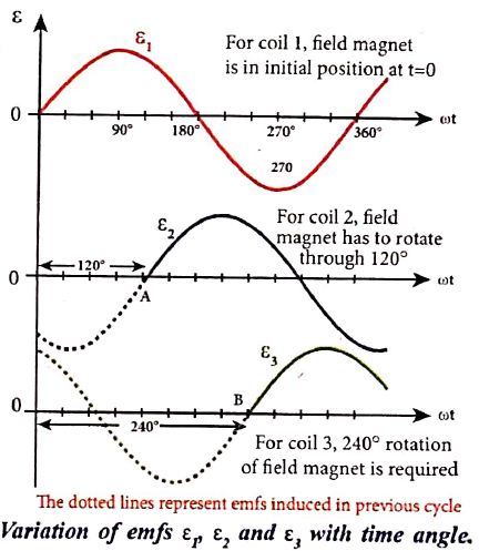
(v) The corresponding cycle for alternating emf ε2 in coil 2 starts at point A after field magnet has rotated through 120°. Therefore, the phase difference between ε1 and ε2 is 120°. Similarly, emf ε3 in coil 3 would begin its cycle at point B after 240° rotation of field magnet from initial position. Thus these emfs produced in the three phase AC generator have 120° phase difference between one another.
27.
(i) Self inductance of a coil is desined as the flux linkage with the coil, when a current of 1 A flows through it.
\(L=\frac{{ N\Phi }_{ B }}{i}\)
\(L={ N\Phi }_{ B }\)
(ii) Self inductance of a coil is defined as the opposing emf induced in the coil when the rate of change of current through the coil is 1 A s-1
\(\varepsilon =\frac { d{ (N\Phi }_{ B }) }{ dt } \)
\(=-\frac { d(Li) }{ dt }\)
\(\varepsilon =-L\frac { di }{ dt } \)
L = -e
28.
Emission spectra:
When the spectrum of self luminous source is taken, we get emission spectrum. Each source has its own characteristic emission spectrum. The emission spectrum can be divided into three types:
(i) Continuous emission spectra (or continuous spectra) :
(a) If the light from incandescent lamp (filament bulb) is allowed to pass through prism (simplest spectroscope), it splits into seven colours.
(b) Thus, it consists of wavelengths containing all the visible colours ranging from violet to red (in the figure). Examples: spectrum obtained from carbon arc, incandescent solids.
(ii) Line emission spectrum (or line spectrum) :
(a) Suppose light from hot gas is allowed to pass through a prism, line spectrum is observed. Line spectra are also known as discontinuous spectra. The line spectra consists of sharp lines of definite wavelengths or frequencies.
(b) Such spectra arise due to excited atoms of elements. These lines are the characteristics of the element and are different for different elements. Examples: spectra of atomic hydrogen, helium, etc.
(iii) Band emission spectrum (or band spectrum) :
(a) Band spectrum consists of several number of very closely spaced spectral lines which overlapped together forming specific bands which are separated by dark spaces.
(b) This spectrum has a sharp edge at one end and fades out at the other end. Such spectra arise when the molecules are excited.
(c) Band spectrum is the characteristic of the molecule hence, the structure of the molecules can be studied using their band spectra. Examples, spectra of hydrogen gas, ammonia gas in the discharge tube, etc.
29.
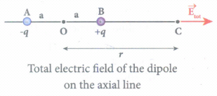
Case (i): Electric field due to an electric dipole at points on the axial Iine:
Consider an electric dipole placed on the x-axis as shown in Figure. A point C is located at a distance of r from the midpoint O (of the dipole) along the axial line.
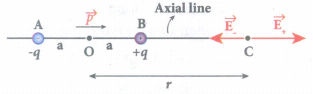
The electric field at a point C due to +q is
\({ \vec { E } }_{ + }=\frac { 1 }{ 4\pi { \varepsilon }_{ 0 } } \frac { q }{ { (r-a) }^{ 2 } } \) along BC
Since the electric dipole moment vector \(\vec { p } \) is from -q to +q and is directed along BC, the above equation is rewritten as
\({ \vec { E } }_{ + }=\frac { 1 }{ 4\pi { \varepsilon }_{ 0 } } \frac { q }{ { (r-a) }^{ 2 } } \hat { p } \) ....(1)
When \(\vec { p } \) is the electric dipole moment unit vector from -q to +q. The electric field at a point C due to -q is
\({ \vec { E } }_{ - }=-\frac { 1 }{ 4\pi { \varepsilon }_{ 0 } } \frac { q }{ { (r+a) }^{ 2 } } \hat { p } \) ....(2)
Since +q is located closer to the point C than -q, \({ \vec { E } }_{ + }\) is stronger than \({ \vec { E } }_{ - }\). Therefore, the length of the \({ \vec { E } }_{ + }\) vector is drawn larger than that of \({ \vec { E } }_{ - }\) vector.
The total electric field at point C is calculated using the superposition principle of the electric field.
\({ \vec { E } }_{ tot }={ \vec { E } }_{ + }+{ \vec { E } }_{ - }\)
\(=\frac { 1 }{ 4\pi { \varepsilon }_{ 0 } } \frac { q }{ { (r-a) }^{ 2 } } \hat { p } -\frac { 1 }{ 4\pi { \varepsilon }_{ 0 } } \frac { q }{ { (r+a) }^{ 2 } } \hat { p } \)
\({ \vec { E } }_{ tot }=\frac { q }{ 4\pi { \varepsilon }_{ 0 } } \left( \frac { 1 }{ { (r-a) }^{ 2 } } -\frac { 1 }{ { (r+a) }^{ 2 } } \right) \hat { p } \) ....(3)
\({ \vec { E } }_{ tot }=\frac { 1 }{ 4\pi { \varepsilon }_{ 0 } } q\left( \frac { 4ra }{( { r }^{ 2 }-{ a }^{ 2 })^2 } \right) \hat { p } \) ...(4)
Note that the total electric field is along \({ \vec { E } }_{ + }\), since +q is closer to C than -q.
If the point C is very far away from the dipole then (r >> a). Under this limit the term \(({ r }^{ 2 }-{ a }^{ 2 })\approx { r }^{ 2 }\).
Substituting this into equation (4), we get
\({ \vec { E } }_{ tot }=\frac { 1 }{ 4\pi { \varepsilon }_{ 0 } } \left( \frac { 4aq }{ { r }^{ 3 } } \right) \hat { p } (r>>a)\)
\(since\quad 2aq\hat { p } =\vec { p } \)
\({ \vec { E } }_{ tot }=\frac { 1 }{ 4\pi { \varepsilon }_{ 0 } } \frac { 2\vec { p } }{ { r }^{ 3 } } (r>>a)\) ...(5)
The direction \({ \vec { E } }_{ tot }\) is shown in Figure.
NOTE: If the point C is chosen on the left side of the dipole, the total electric field is still in the direction of \(\vec { p } \).
Case (ii) Electic field due to an electric dipole at a point on the equatorial plane:
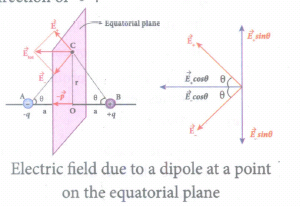
Consider a point C at a distance r from the midpoint O of the dipole on the equatorial plane. Since the point C is equidistant from +q and -q, the magnitude of the electric fields of +q and -q are the same. The direction of \({ \vec { E } }_{ + }\) is along BC and the direction of \({ \vec { E } }_{ - }\) is along CA. \({ \vec { E } }_{ + }\) and \({ \vec { E } }_{ - }\) are resolved into two components; one component parallel to the dipole axis and the other perpendicular to it. The perpendicular components \(|{ \vec { E } }_{ + }|\) sinθ and \(|{ \vec { E } }_{ -}|\) sinθ are equal in magnitude and oppositely directed and cancel each other. The magnitude of the total electric field at point C is the sum of the parallel components of \({ \vec { E } }_{ + }\) and \({ \vec { E } }_{ - }\) and its direction is along \(-\hat{p}\) as shown in the Figure.
\({ \vec { E } }_{ tot }=-|{ \vec { E } }_{ + }|cos\theta \hat { p } -|{ \vec { E } }_{ - }|cos\theta \hat { p } \) ...(6)
The magnitudes \({ \vec { E } }_{ + }\) and \({ \vec { E } }_{ - }\) are the same and given by,
\(|{ \vec { E } }_{ + }|=|{ \vec { E } }_{ - }|=\frac { 1 }{ 4\pi { \varepsilon }_{ 0 } } \frac { q }{ (r^2+a^2) } \) ...(7)
By substituting equation (7) into equation (6), we get
\({ \vec { E } }_{ tot }=\frac { 1 }{ 4\pi { \varepsilon }_{ 0 } } \frac { 2qcos\theta }{ ({ r }^{ 2 }+{ a }^{ 2 }) } \hat { p } ....(8)\)
\(=-\frac { 1 }{ 4\pi { \varepsilon }_{ 0 } } \frac { 2qa }{ ({ r }^{ 2 }+{ a }^{ 2 })^{ \frac { 3 }{ 2 } } } \hat { p } \)
Since \(cos \theta =\frac { a }{ \sqrt { { r }^{ 2 }+{ a }^{ 2 } } } \)
\({ \vec { E } }_{ tot }=\frac { 1 }{ 4\pi { \varepsilon }_{ 0 } } \frac { \vec { p } }{ ({ r }^{ 2 }+{ a }^{ 2 })^{ \frac { 3 }{ 2 } } } \)
Since \(\vec { p } \) = 2qa\(\hat { p } \) ...(9)
At very large distances (r >> a), the equation (9) becomes
\({ \vec { E } }_{ tot }=\frac { 1 }{ 4\pi { \varepsilon }_{ 0 } } \frac { \vec { p } }{ { r }^{ 3 } } (r>>a)\) ...(10)
Negative sign shows that direction of Electric field is opposite to the direction of dipole moment vector.
30.
(i) The meter bridge is another form of Wheatstone's bridge. It consists of a uniform manganin wire AB of one meter length.
(ii) This wire is stretched along a meter scale on a wooden board between two copper strips C and D. Between these two copper strips another copper strip E is mounted to enclose two gaps G1 and G2.
(iii) An unknown resistance P is connected in G1 and a standard resistance Q is connected in G2. A jockey (conducting wire) is connected to the terminal E on the central copper strip through a galvanometer (G) and a high resistance (HR).
(iv) The exact position of jockey on the wire can be read on the scale. A Lechlanche cell and a key (K) are connected across the ends of the bridge wire.

(v) The position of the jockey on the wire is adjusted so that the galvanometer shows zero deflection. Let the position of jockey at the wire be at J.
(vi) The resistances corresponding to AJ and JB of the bridge wire now form the resistance R and S of the Wheatstone's bridge. Then for the bridge balance.
\(\cfrac { P }{ Q } =\cfrac { R }{ S } =\cfrac { { r }.AJ }{ { r }.JB } \)
where r' is the resistance per unit length of wire
\(\cfrac { P }{ Q } =\cfrac { AJ }{ JB } =\cfrac { { l }_{ 1 } }{ { l }_{ 2 } } \)
\(P=Q\cfrac { { l }_{ 1 } }{ { l }_{ 2 } } \)
(vii) By interchanging P and Q, another set of readings are taken and the average value of P is value of unknown resistance.

12th Standard Syllabus & Materials
12th Standard
TN 12th Computer Applications களப்பெயர் முறைமை (DNS) Sample Question Papers Study Material - QB365 Set A
NEW12th Standard
TN 12th Computer Applications வலையமைப்பு எடுத்துக்காட்டுகள் மற்றும் நெறிமுறைகள் Sample Question Papers Study Material - QB365 Set A
NEW12th Standard
TN 12th Computer Applications கணினி வலையமைப்பு ஓர் அறிமுகம் Sample Question Papers Study Material - QB365 Set A
NEW12th Standard
TN 12th Computer Applications PHP-உடன் MySQL-ஐ இணைத்தல் Sample Question Papers Study Material - QB365 Set A



Tamilnadu Stateboard 12th Standard Subjects

Maths

Chemistry
Physics

Biology

Computer Science

Business Maths and Statistics

Economics

Commerce

Accountancy

History

Computer Applications
Biology
Computer Technology
Computer Applications
Computer Science
Business Maths and Statistics
Commerce
Economics
Maths
Chemistry
Physics
Computer Technology
History
Accountancy

Tamil

English

French
Tamilnadu Stateboard Standards

