
 100% FREE ACCESS
12th Standard Syllabus & Materials
12th Standard
TN 12th Computer Applications மின்னணு தரவு பரிமாற்றம் Sample Question Papers Study Material - QB365 Set A
NEW12th Standard
TN 12th Computer Applications மின் - வணிக பாதுகாப்பு அமைப்புகள் Sample Question Papers Study Material - QB365 Set A
NEW12th Standard
TN 12th Computer Applications மின்னணு செலுத்தல் முறைகள் Sample Question Papers Study Material - QB365 Set A
NEW12th Standard
TN 12th Computer Applications மின் - வணிகம் Sample Question Papers Study Material - QB365 Set A
NEW12th Standard
TN 12th Computer Applications திறந்த மூல கருத்துருக்கள் Sample Question Papers Study Material - QB365 Set A
NEW12th Standard
TN 12th Computer Applications வலையமைப்பு வடமிடல் Sample Question Papers Study Material - QB365 Set A

Published on: 26/01/2021
12th Standard Physics English Medium Reduced Syllabus Important Questions - 2021 Part - 2
Download Tamil Nadu 12th Standard Physics question papers, model tests, one-mark questions, important questions, and public exam papers in PDF format. Free study materials and answer keys for TN State Board students.
Questions + Answers key
Take MCQ Physics Test1.
Define internal field emission or field ionization.
2.
What are Permanent magnets ? State examples
3.
What is Geomagnetism?
4.
The motion of copper plate is damped when it is allowed to oscillate between the two poles of a magnet what is the cause of this damping?
5.
What is the value of power if the circuit is
(i) purely resistive
(ii) Purely inductive or capacitive?
6.
What is meant by power transmission?
7.
What is an internal resistance of cell?
8.
Define Ampere.
9.
State Ampere’s circuital law.
10.
State Biot-Savart’s law.
11.
Give any one definition of power factor.
12.
What is Seebeck effect?
13.
What do you mean by internal resistance of a cell?
14.
A battery has an emf of 12 V and connected to a resistor of 3 Ω. The current in the circuit is 3.93 A. Calculate
(a) terminal voltage and the internal resistance of the battery
(b) power delivered by the battery and power delivered to the resistor
15.
What is electric power and electric energy?
16.
It is possible for two lenses to produce zero power?
17.
With respect to power generation, what are the relative advantages and disadvantages of fusion type and Fission type reactors?
18.
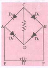
Four silicon diodes and a 10 Ω resistor are connected as shown in figure below. Each diode has a resistance of 1Ω. Find the current flows through the 10Ω resistor.
19.
How does Ampere - Maxwell law expalain the flux of current trough a capacitor when it is being charged by a battery? write the expression for the displacement current in terms of the rate of change of electric flux.
20.
Tabulate the difference between Coulomb's law and Biot-Savort's law.
21.
What are the types of magnets? Give example.
22.
What is the phase difference between
(i) the voltage across L and C in an LCR circuit connected to an a.c source
(ii) applied a.c voltage and current in LCR circuit at resonance?
23.
In a circuit containing internal resistance r. Find the power delivered.
24.
Derive a relation between internal resisance and emf of a cell.
25.
What are carbon resistors? What does the colour indicates?
26.
The solenoids S1 and S2 are wound on an iron-core of relative permeability 900. The areas of their cross-section and their length are the same and are 4 cm2 and 0.04 m respectively. If the number of turns in S1 is 200 and that in S2 is 800. Calculate the mutual inductance between the solenoids. If the current in solenoid 1 is increased form 2A to 8A in 0.04 second. Calculate the induced emf in solenoid 2.
27.
Two air core solenoids have the same length of 80 cm and same cross-sectional area 5 cm2. Find the mutual inductance between them if the number of turns in the first coil is 1200 turns and that in the second coil is 400 turns.
28.
An electron moving perpendicular to a uniform magnetic field 0.500 T undergoes circular motion of radius 2.50 mm. What is the speed of electron?
29.
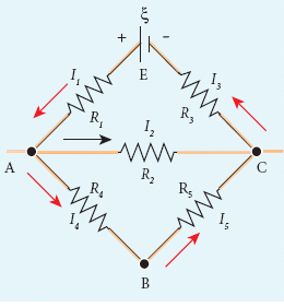
The following figure shows a complex network of conductors which can be divided into two closed loops like EACE and ABCA. Apply Kirchoff’s voltage rule(KVR)
30.
Internal frames are _______ frames.
variable
accelerated
unaccelerated
varying
31.
When an electric field is applied to an atom each of the spectral lines split into several lines. This effect is known as ________________.
Zeeman effect
Stark effect
Raman effect
Seebeck effect
32.
The word 'Magnetism' was derived from Iron are _________
Fe3O2
Fe3O3
Fe3O4
Fe2O3
33.
The direction of the magnetic field due to a solenoid is given by ___________________.
Amperes circuital law
Biot-Savart law
Right hand palm rule
Flemings right hand law
34.
Which one of the following is correct. According to Biot-Savart law, the magnetic induction is directly proportional to _________________.
Square of the current
Square root of the current
Length of the current element
Square of the distance
35.
The necessary magnetic field for a low power a.c generator is produced by _________
electric coil
permanent magnets
electromagnets
batteries
36.
Kirchoff's II law isa consequence of conservation of________
charges
momentum
energy
power
37.
Peltier effect is the converse of _____________.
Joule effect
Raman effect
Thomson effect
Seebeck effect
38.
The emf of a battery is 3 volts and internal resistance 0.125 \(\Omega \) . The difference of potential at the terminal of battery when connected across an external resistance of 1 \(\Omega \) is ______________.
1.67 V
0.67 V
2.67 V
3.67 V
39.
The internal resistance of a 2.1 V cell which gives a current of 0.2 A through a resistance of 10 Ω is ______.
0.2 Ω
0.5 Ω
0.8 Ω
1.0 Ω
40.
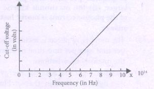
For photo electronic effect in sodium, the figure shows the plot of cut-off voltage versus frequency of incident radiation. Calculate
(i) threshold frequency
(ii) work function for sodium.
41.
(i) Define the term 'intensity of radiation' in a photon picture.
(ii) Plotagraph showing the variation of photocurrent vs collector potential for three different intensities I1 > I2> I3 two of which (I1 and I2) have the same frequency v and the third has frequency v1 > v.
(iii) Explain the nature of the curves on the basis of Einstein's equation.
42.
Explain current transfer characteristics.
43.
Draw the circuit diagram of a half-wave rectifier and explain its working.
44.
Obtain the equation for resolving power of optical instruments.
45.
What is dispersion? Obtain the equation for dispersive power of a medium.
46.
Show how to generalize Ampere's circuital law to include the term due to displacement current?
47.
Describe the motion of a charged particle in a uniform magnetic field.
48.
The current flowing in two coils of self inductance L1 = 20mH and L2 = 15mH are increasing at the same rate. If the power supplied to the two coils are equal. Find the ratio of
(i) induced emf
(ii) induced current and
(iii) the energies stored in the two coils at a given instant.
49.
Explain the mutual induction between two long solenoids. Obtain an expression for the mutual inductance.
50.
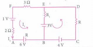
Use Kirchhoff's laws (rules) to determine the potential difference between points A and D when no current flows in the arm BE of the electric network shown in the figure below.
51.
Explain what is
(i) Thomson effect,
(ii) Positive Thomson effect,
(iii) Negative effect.
52.
Find the magnetic field due to a long straight conductor using Ampere’s circuital law.
53.
Obtain an expression for average power of AC over a cycle. Discuss its special cases.
54.
Find out the phase relationship between voltage and current in a pure inductive circuit.
55.
Establish the fact that the relative motion between the coil and the magnet induces an emf in the coil of a closed circuit.
1.
The process of emission of electrons due to the rupture of bands in from the lattice due to strong electric field is known as internal field emission or field ionization.
2.
The materials with high retentivity, high coercivity and high permeability are suitable for making permanent magnets.
Examples: Steel and Alnico.
3.
The branch of physics which deals with the Earth's magnetic field is called Geomagnetism or Terrestrial magnetism.
4.
(i) As the plate oscillate, the changing magnetic flux through the plate produces a strong eddy current in the direction, which opposes the cause.
(ii) Also copper being diamagnetic substance, it gets magnetised in the opposite direction, so the motion of copper plate is stopped.
5.
(i) For a purely resistive circuit, the phase angle between voltage and current is zero and cos Φ = 1
ஃ Pav = VRMSIRMS
(ii) For a purely inductive or capacitive circuit, the phase angle is ±\(\frac { \pi }{ 2 } \) and cos \(\left( \pm \frac { \pi }{ 2 } \right) \)
6.
Most of the power stations are located in remote places. Hence the electric power generated is transmitted over long distances through transmission lines to reach towns or cities where it is actually consumed. This process is called power transmission.
7.
The resistance by the electrolytic of a cell to the flow of circuit between its electrodes is called internal resistance.
8.
1 A of current is equivalent to 1 Coulomb of charge passing through a perpendicular cross-section in Second. The electric current is a scalar quantity.
9.
Ampere's circuital law states that the line integral of magnetic field over a closed loop is μ0, times net current enclosed by the loop.
\(\oint _{ c }^{ }{ \vec { B } \vec { dl } } \) = μ0I enclosed.
10.
Biot-Savart's law states that, the magnitude of magnetic field \(d\vec { B } \) at a point P at a distance of r from the small elemental length taken on a conductor carrying current varies
(i) directly as the strength of the current I
(ii) directly as the magnitude of the length of element \(\vec { dl } \)
(iii) directly as the sine of the angle θ between \(\vec { dl } \) and \(\hat { r } \).
(iv) inversely as the square of the distance r between the point P and length of element \(\vec { dl } \).
\(d\vec { B } =\frac { { \mu }_{ 0 } }{ 4\pi } \frac { I\vec { dl } \times \hat { r } }{ { r }^{ 2 } } \)
11.
Power factor is defined as the ratio of resistance to the impedance of an AC circuit
Power factor \(\cos \phi=\frac{R}{2}\)
\(=\frac{Resistance}{Impedance}\)
12.
Seebeck discovered that in a closed circuit consisting of two dissimilar metals, when the junctions are maintained at different temperature an emf is developed.
13.
The internal resistance of a cell is the resistance offered to the flow of current (by the electrolyte) inside the cell.
14.
The given values I = 3.93 A, ξ = 12 V,
R = 3 Ω
(a) The terminal voltage of the battery is equal to voltage drop across the resistor
V = IR = 3.93 x 3 = 11.79 V
The internal resistance of the battery,
\(r=\left[ \frac { \xi -V }{ V } \right] R=\left[ \frac { 12-11.79 }{ 11.79 } \right] \times 3=0.05\Omega \)
(b) The power delivered by the battery P = Iξ = 3.93 x 12 = 47.1 W
The power delivered to the resistor = I2 R = 46.3 W
The remaining power = (47.1 – 46.3) = 0.8 W is delivered to the internal resistance and cannot be used to do useful work. (it is equal to I2 r).
15.
Electric power:
(i) The electric power P is the rate at which the electrical potential energy is delivered.
(ii) The electric power P is the rate at which the work is done.
\( P= \frac{d U}{d t} (or)= \frac{d W}{d t} (or)=VI(or)\frac{V^2}{R}\)
Unit: watt (W)
Electric energy:
(i) The electric energy is the product of power (P) and duration of the time (t) when electric energy is delivered.
(ii) E = Pt
Unit: watt-hour (Wh)
16.
Yes, It is possible for two lens to produce zero power.
Explanation:
when the two lens (one is concave & another one is convex lens) are combined together, the focal length of the combination of the two lenses is F.
Then
\(\frac{1}{F}=\frac{1}{f_{1}}+\frac{1}{f_{2}} \)
\(\text { if } f_{1}=f_{2}=f \)
\(f_{1}=f(\text { convex }) \)
\(f_{2}=-f(\text { concave) } \)
\(P=\frac{1}{F}=\frac{1}{f}-\frac{1}{f}=0 . \ P \rightarrow \text { power } \)
17.
(i) Fusion requires high temperature controlled reaction is not yet obtained. Highly sophisticated technology will be required.
(ii) However, the fuel is easily available, cheap and causes very less pollution.
(iii) There is no problem of waste management.
(iv) Fission controlled chain reaction is possible. The technology is well developed and established.
(v) There also exists the problem of waste management.
18.
Diode D1 and D4 is reverse biased [open]
Diode D1 and D3 are forward biased.
The resistances are in series
R = 1 + 10 + 1 - 12 Ω
Barier Potential, V = 0.7 + 0.7 = 1.4 V (Silicon diode)
Applying Kirchhoff's voltage Law,
0.7 + I(1) + I(10) + 0.7 + I(1) = 3V
12 I = 3 - 1.4
12 I = 1.6
\(I=\frac{1.6}{12}=\mathbf{0 . 1 3 3 A}\)
19.
During charging, the electric flux between the plates capacitor keeps on changing. This results in the production of displacement current between the plates.
\({ I }_{ d }=\varepsilon _{ 0 }\left( \frac { d{ \phi }_{ E } }{ dt } \right) \)
20.
| S.No | Electric field | Magnetic field |
| (i) | Produced by a scalar source i.e., an electric charge q | Produced by a vector source i.e., current element I\(\vec { dl } \) |
| (ii) | It is directed along the position vector joining the source and the point at which the field is calculated. | it is directed perpendicular to the position vector \(\hat { r } \) and the current element I\(\vec { dl } \) |
| (iii) | Does not depend on the angle | Depends on the angle between the position vector \(\hat { r } \) and the current element I\(\vec { dl } \) |
21.
(i) Magnets are classified into natural magnets and artificial magnets.
(ii) For example, iron, cobalt, nickel, etc. are natural magnets.
(iii) Strengths of natural magnets are very weak and the shapes of the magnet are irregular.
(iv) Artificial magnets are made by us in order to have desired shape and strength.
(v) If the magnet is in the form of rectangular shape or cylindrical shape, then it is known as bar magnet.
22.
(i) 1800 (or) π radian
(ii) Zero.
23.
(i) Due to this internal resistance, the power delivered to the circuit is not equal to power rating mentioned in the battery.
(ii) For a battery of emf \({ \xi }_{ 1 }\) with an internal resistance r, the power delivered to the circuit of resistance R is given by
\(P=I\xi =I(V+Ir)\)
Here V is the voltage drop across the resistance R and it is equal to IR.
Therefore, P = I (IR +Ir)
P = I2 R + I2 r
(iii) Here Pr is the power delivered to the internal resistance and PR is the power delivered to the electrical device (here it is the resistance R). For a good battery, the internal resistance r is very small, then for P < r < P
24.
(i) The emf of cell \(\xi \) is measured by connecting a high resistance voltmeter across it without connecting the external resistance R.
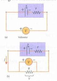
(ii) Since the voltmeter draws very little current for deflection, the circuit may be considered as open. Hence the voltmeter reading gives the emf of the cell.
(iii) Then, external resistance R is included in the circuit, and current I is established in the circuit. The potential difference across R is equal to the potential difference across the cell (V).
(iv) The potential drop across the resistor R is V + IR
(v) Due to internal resistance r of the cell, the voltmeter reads a value V, which is less than the emf of cell . It is because a certain amount of voltage (Ir) has dropped across the internal resistance r.
Then \(V=\xi -Ir\)
\(Ir=\xi -V\)
(vi) Dividing equation (2) by equation (1) we get
\(\cfrac { Ir }{ IR } =\cfrac { \xi -V }{ V } \)
\(r=\left| \cfrac { \xi -V }{ V } \right| R\)
Since \(\xi \) V and R are known, internal resistance r can be determined.
25.
(i) Carbon resistors consists of a ceramic core, on which a thin layer of crystalline Carbon is deposited. These resistors are inexpensive, stable and compact in size. Color rings are used to indicate the value of the resistance.
(ii) Three coloured rings are used to indicate the values of a resistor: the first two rings are significant figures of resistances, the third ring indicates the decimal multiplier after them. The fourth color, silver or gold shows the tolerance of the resistor.
| Color | Number | Multiplier | Tolerance |
|---|---|---|---|
| Black | 0 | 1 | - |
| Brown | 1 | 101 | - |
| Red | 2 | 102 | - |
| Orange | 3 | 103 | - |
| Yellow | 4 | 104 | - |
| Green | 5 | 105 | - |
| Blue | 6 | 105 | - |
| Violet | 7 | 107 | - |
| Gray | 8 | 107 | - |
| White | 9 | 109 | - |
| Gold | - | 10-1 | 5% |
| Slive | - | 10-2 | 10% |
| Colorless | - | - | 20% |
26.
Relative permeability of an iron core = μr = 900
Area of cross-section, A1 = A2 = 4 x 10⁻⁴ m-2
Current in solenoid, \(\mathrm{I}=1_2-I_1=8-2=6 \mathrm{~A}, Length, l_1=l_2=4 \times 10^{-2} \mathrm{~m}=0.04 \mathrm{~m} \)
Number of turns in S1 = N1 = 200, Number of turns in S2 = N2 = 800,
\(\text {Mutual inductance } M =\frac{\mu_0 \mu, \mathrm{N}_1 \mathrm{~N}_2 A_2}{l} \)
\(\therefore M =\frac{4 \times 3.14 \times 10^{-7} \times 900 \times 200 \times 800 \times 4 \times 10^{-4}}{4 \times 10^{-2}} \)
M = 1.81 H
\(\text {Induced emf } e =-M \frac{d I}{d t} \)
\(=-1.81 \times \frac{6}{0.04}=-271.5 \mathrm{~V} \)
\(M=1.81 \mathrm{H}, \text { Induced } \mathrm{emf} e =-271.5 \mathrm{~V}\)
27.
μr = 1 (air core)
Length of two solenoids, \(l_1=l_2=80 \times 10^{-2} \mathrm{~m}\)
Cross-sectional area of two solenoids, \(A_1=A_2=5 \times 10^{-4} \mathrm{~m}^2\)
Number of turns in the first coll, N1=1200 turns
Number of turns in the second coil, N2 = 400 turns
\(n_1=\frac{N_1}{l}=\frac{1200}{80 \times 10^{-2}}=15 \times 10^{-2}=1500 \)
\(n_2=\frac{N_2}{l}=\frac{400}{80 \times 10^{-2}}=500\)
Mutual inductance, \(M= μ_0μ_r n_1 n_2 A_2 l\)
\(M =4 \times 3.14 \times 10^{-7} \times 1 \times 1500 \times 500 \times 5 \times 10^{-4} \times 80 \times 10^{-2} \)
\(=12.56 \times 10^{-7} \times 75 \times 10^4 \times 5 \times 10^{-4} \times 80 \times 10^{-2} \)
\(=3.76,800 \times 10^{-9}=0.376 \times 10^{-3} \mathrm{H}=0.376 \mathrm{mH} \)
\(=0.38 \mathrm{mH} \)
\(\therefore \text {Mutual inductance } =0.38 \mathrm{mH}\)
28.
Charge of an electron q = –1.60 × 10⁻¹⁹ C ⇒ |q| = 1 60 x 10-19 C
Magnitude of magnetic field B = 0.500 T
Mass of the electron, m = 9.11 × 10⁻³¹ kg
Radius of the orbit, r = 2.50 mm = 2.50 × 10⁻³ m
Speed of the electron, V = \(q \frac{\mathrm{rB}}{\mathrm{m}}\)
\( v = 1.60 \times 10^{-19} \times\frac{ 2.50 \times 10^{-3} \times 0.500}{9.11 \times 10^{-31}}\)
\(v=2.195 \times 10^8 \mathrm{~m} \mathrm{s} ^{-1}\)
29.
Thus applying Kirchoff’s second law to the closed loop EACE
I1R1 + I2R2 + I3R3 = ξ
and for the closed loop ABCA
I4R4 + I5R5 - I2R2 = 0
30.
(c)
unaccelerated
31.
(b)
Stark effect
32.
(c)
Fe3O4
33.
(c)
Right hand palm rule
34.
(c)
Length of the current element
35.
(b)
permanent magnets
36.
(c)
energy
37.
(d)
Seebeck effect
38.
(c)
2.67 V
39.
I = 0.2 A, R = 10 Ω, E = 2.1 V
\(I=\frac{ɛ}{R+r}\)
\(0.2=\frac{2.1}{10+r}\)
0.2 x (10 + r) = 2.1
2 + 0.2 r = 2.1
0.2 r = 2.1 - 2 = 0.1
Internal resistance, \(r=\frac{0.1}{0.2}=\frac{1}{2}\)
r = 0.5 Ω
40.
(i) The threshold frequency is the frequency of incident light at which kinetic energy of ejected photoelectron is zero.
∴ From fig. threshold frequency,
v0 = 4.5 x 10¹⁴ Hz
(ii) Work function, W = hv0
= 6.6 x 10-34 x 4.5 x 1014 joule
= \(\frac { 6.6\times { 10 }^{ -34 }\times 4.5\times 10^{ 14 } }{ 1.6\times { 10 }^{ -19 } } \) eV
= 1.85 eV
41.
(i) The amount of light energy or photon energy incident per metre square per second is called intensity of radiation.
(ii) 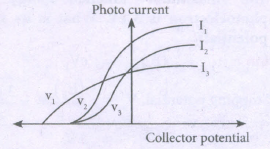
(iii) As per Einstein's equation,
(a) The stopping potential is the same for I1 and I2 as they have the same frequency.
(b) The saturation currents are as shown in the figure because of I1 > I2 > I3.
42.
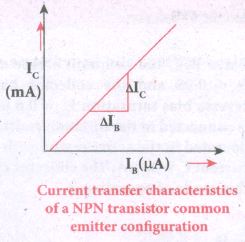
(i) This gives the variation of collector current (IC) with changes in base current (IB) at constant collector-emitter voltage (VCE).
(ii) It is seen that a small Ie flows even when IB is zero. This current is called the common emitter leakage current (ICEQ) which is due to the flow of minority charge carriers.
Forward current gain:
(i) The ratio of the change in collector current (ΔIC) to the change in base current (ΔIB) at constant collector-emitter voltage (VCE) is called forward current gain(β)
\(\beta ={ \left( \frac { \triangle { I }_{ C } }{ \triangle { I }_{ B } } \right) }_{ { V }_{ CE } }\)
(ii) It is value is very high and it generally ranges from 50 to 200. It depends on the construction of the transistors and will be provided by the manufacturer.
43.
HaIf wave rectifier:
Only one half of the input wave reaches the output. Therefore it is called half wave rectifier.
Construction:
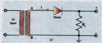
(i) The circuit consists of a transformer, a p-n junction diode and a resistor
(ii) In a half wave rectifier circuit, either a positive half or the negative half of the AC input is passed through by the diode while the other half is blocked
(iii) It acts as a rectifier diode.
.jpg)
(iv) Efficiency (η) is the ratio of the output DC power to the AC input power circuit. supplied to the circuit.
(v) The efficiency (η) of a half wave rectifier is found to be 40.6 %.
.jpg)
44.
(i) The effect of diffraction has an adverse effect in the sharpness of the image tormed.
(ii) There is always a spread of central maximum in the image for every point of the object, for every point of the object acts as a point source.
(iii) The condition for central maximum (or first minimum) produced by rectangular slit is given by the equation,
\(a \sin \theta=\lambda\) ....(1)
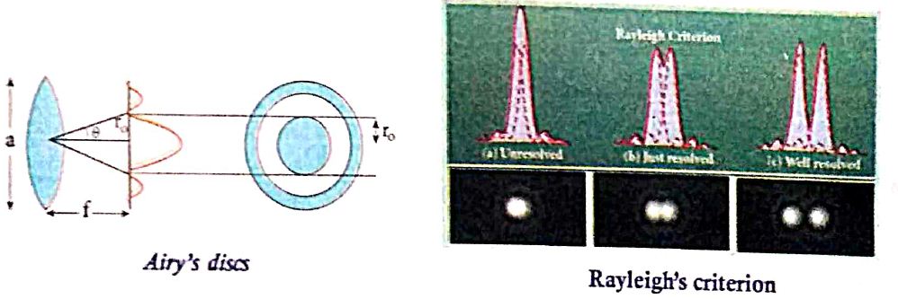
(iv) But, a circular slit (aperture) produces diffraction pattern of concentric circles as shown in Figure.
(v) These are known as Airy's discs. Most of the optical instruments form images of objects only through the circular slits.
(vi) The condition for central maximum (or) first minimum for circular slit is,
\(\text { a } \sin \theta=1.22 \lambda\) .....(2)
(vii) Here, the numerical value 1.22 appears in the expression for central maximum (or) first minimum formed by circular slits.
For small angles,\(sin\theta = \theta\), the above equation becomes,
\(a\theta = 1.22\lambda\)
Rewriting further,
\(\theta=\frac{1.22 \lambda}{a}\) ......(3)
Form thegeometry, \(\theta=\frac{r_0}{f}\)
Substituting for in equation (3) and rearranging gives
\(r_0=\frac{1.22 \lambda f}{a}\) ....(4)
(viii) For example, let two point-sources of light close to cach other form image on a screen. The diffraction pattern of one point-source may overlap with another and produce a blurred image (or) un-resolved image as shown in Figure (a). To obtain a quality image (or) well resolved image, the two point-sources must be kept apart in such a way that their diffraction patterns do not overlap as shown in Figure (c).
(ix) According to Rayleigh's criterion, the two points on an image are said to be just resolved when the central maximum of one diffraction pattern coincides with the first minimum of the other and vice-versa as shown in Figure (b).
45.
Dispersion: It is splitting of white light into its constituent colours.
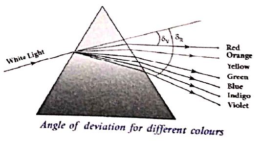
(i) Consider a beam of white light passes through a prism; it gets dispersed into its constituent colours as shown in Figure.
(ii) Let \(\delta_{v}, \delta_{R} \) are the angles of deviation for violet and red light. Let nV and nR are the refractive indices for the violet and red light respectively
(iii) The refractive index of the material of a prism is given by the equation
\(\mathrm{n}=\frac{\sin \left(\frac{\mathrm{A}+\mathrm{D}}{2}\right)}{\sin (\mathrm{A} / 2)}\)
(iv) Here A is the angle of the prism and D is the angle of minimum deviation. If the angle of prism is small of the order of 10o, the prism is said to be a small angle prism.
(v) When rays of light pass through such prisms, the angle of deviation also becomes small. If A be the angle of a smitt angle prism and the angle of deviation then the prism formula becomes.
\(n=\frac{\sin \left(\frac{A+\delta}{2}\right)}{\sin (A / 2)}\)
For small angles of \(A\ and \ \delta \)
\(\sin \frac{A+\delta}{A} \approx \frac{A+\delta}{A} \)
\(\sin \frac{A}{2} \approx \frac{A}{2} \)
\(n=\frac{(A+\delta / 2)}{(A / 2)}=\frac{A+\delta}{A}=1+\frac{\delta}{A} \)
Further simplifying,
\(\frac{\delta}{A} =n-1 \)
\(\delta =(n-1) A \) .....(1)
(vi) When white light enters the prism, the deviation is different for different colours. Thus, the refractive index is also different for different colours
For Violet colour, \( \delta_{\mathrm{v}}=\left(\mathrm{n}_{\mathrm{v}}-1\right) \mathrm{A} \) ...(2)
For Red colour, \(\delta_{\mathrm{R}}=\left(\mathrm{n}_{\mathrm{R}}-1\right) \mathrm{A} \) ....(3)
(vii) As, angle of deviation for violet colour \(\delta_{v}\) is greater the angle of deviation for red colour \(\delta_{\mathrm{R}}\) the refractive index for violet colour nv is greater than the refractive index for red colour nR Subtracting \(\delta_{v}\) from \(\delta_{\mathrm{R}}\) we get
\(\delta_{\mathrm{v}}-\delta_{\mathrm{R}}=\left(\mathrm{n}_{\mathrm{v}}-\mathrm{n}_{\mathrm{R}}\right) \mathrm{A}\) ....(4)
(viii) The term \(\left(\delta_{v}-\delta_{R}\right)\) is the angular separation between the two extreme colours (violet and red) in the spectrum is called the angular dispersion. If we take \(\delta\) is the angle of deviation for any middly ray (green or yellow) and the corresponding refractive index. Then,
\(\delta=(n-1) A\) .....(5)
Dispersive power (ω):
It is the ability of the material of the prism to cause dispersion. It is defined as the ratio of the angular dispersion for the extreme colours to the deviation for any mean colour.
Dispersive power
\(\omega=\frac{\text { Angular dispersion }}{\text { Mean deviation }}=\frac{\delta_{v}-\delta_{R}}{\delta}\) ....(6)
Substituting \(\left(\delta_{\mathrm{v}}-\delta_{\mathrm{R}}\right) \text { and }(\delta) \)
\(\omega=\frac{\mathrm{n}_{\mathrm{v}}-\mathrm{n}_{\mathrm{R}}}{(\mathrm{n}-1)} \) .......(7)
(ix) Dispersive power is a dimensionless quality It has no unit. Dispersive power is always positive. The dispersive power of a prism depends only on the nature of material of the prism and it is independent of the angle of the prism.
46.
According to Ampere's circuital law,
\(\oint _{ s }^{ }{ \overrightarrow { B } .\overrightarrow { dl } } ={ \mu }_{ 0 }I\quad ...(1)\)
As the current flows across the area bounded by loop S1, so
\(\oint _{ { s }_{ 1 },s }^{ }{ \overrightarrow { B } .\overrightarrow { dl } } ={ \mu }_{ 0 }I\quad ...(2)\)
But the area bounded by S2 lies in the region between the plates capacitor where no current flows across it.
\(\therefore \oint _{ { s }_{ 1 } }^{ }{ \overrightarrow { B } .\overrightarrow { dl } } =0\)
Consider that loops enclosing S1 & S2 are infinitesimally close to each other. Then
\(\oint _{ { s }_{ 1 } }^{ }{ \overrightarrow { B } .\overrightarrow { dl } } =\oint _{ { s }_{ 2 } }^{ }{ \overrightarrow { B } .\overrightarrow { dl } } \)
This equation is inconsistent with equations (2) & (3). To remove this maxwell said that a changing electric field (during charging) between the capacitor plates must induce a magnetic field which in turn must be associated with current Id.
\({ I }_{ d }={ \varepsilon }_{ 0 }\left( \frac { d{ \phi }_{ E } }{ dt } \right) \) [\(\frac { d{ \phi }_{ E } }{ dt } \) change in electric flux]
The total current must be
I = Iconduction + Idisplacement
\({ I }_{ c }={ \varepsilon }_{ 0 }\frac { d{ \phi }_{ E } }{ dt } \)
Hence the generalized from of Ampere's circuital law is
\(\oint _{ s }^{ }{ \overrightarrow { B } .\overrightarrow { dl } } ={ \mu }_{ 0 }\left[ { I }_{ c }+{ \varepsilon }_{ 0 }\frac { d{ \phi }_{ E } }{ dt } \right] \)
47.
(i) Consider a charged particle of charge 'q' having mass m enters into a region of a uniform magnetic field \(\vec { B } \) with velocity \(\vec { v } \).
(ii) Such that velocity is perpendicular to the magnetic field and velocity \(\vec{v}\).
(iii) The charged particle moves in a circular orbit.
(iv) Lorentz force.
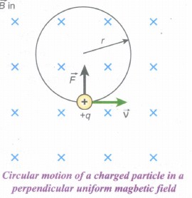
\(\vec { F } =q(\vec { v } \times \vec { B } )\)
In magnitude F = qVB
(v) This Lorentz force acts as centripetal force for the particle to execute circular motion. Therefore,
qvB = m\(\frac { { v }^{ 2 } }{ r } \)
The radius of the circular path is
r = \(\frac { mv }{ qB } =\frac { p }{ qB } \) ..........(1)
(vi) where p = mv is the magnitude of the linear momentum of the particle. Let T be the time taken by the particle to finish one complete circular motion, then
T = \(\frac { 2\pi r }{ v } \) .............(2)
Hence substituting (1) in (2), we get,
T = \(\frac { 2\pi m }{ qB } \) .............(3)
(vii) Equation (3) is called the cyclotron period. The reciprocal of time period is the frequency f, which is
f = \(\frac { 1 }{ T } \)
f = \(\frac { qB }{ 2\pi m } \) ...........(4)
In terms of angular frequency ω,
ω = 2πf = \(\frac { q }{ m } \)B ...........(5)
(viii) Equations (4) and equation (5) are called cyclotron frequency or gyrofrequency.
(ix) Time period and frequency depend only on charge-to-mass ratio (specific charge) and independent of velocity or radius.
48.
(i) Given: Induced emf in the coil e =?
Self-inductance of two coils L1 = 20mH and
L2= 15 mH.
Formula:
\(e=-L\frac { dl }{ dt } \)
\(\frac { { e }_{ 1 } }{ { e }_{ 2 } } =\frac { -{ L }_{ 1 }dI/d }{ { -L }_{ 2 }dI/dt } \)
\(\frac { { L }_{ 1 } }{ { L }_{ 2 } } =\frac { 20 }{ 15 } =\frac { 4 }{ 3 } \)
(ii) Power supplied P = εI
since power is the same for both the coils
\({ e }_{ 1 }{ I }_{ 1 }={ e }_{ 2 }{ I }_{ 2 }\Rightarrow \frac { { e }_{ 2 } }{ { e }_{ 1 } } =\frac { { I }_{ 1 } }{ { I }_{ 2 } } \)
\(\frac { { I }_{ 1 } }{ { I }_{ 2 } } =\frac { 3 }{ 4 } \)
(iii) Energy stored in the coil
\(E=\frac { 1 }{ 2 } { LI }^{ 2 }\)
\(\frac { { E }_{ 1 } }{ { E }_{ 2 } } =\frac { \frac { 1 }{ 2 } { L }_{ 1 }{ { I }^{ 2 } }_{ 1 } }{ \frac { 1 }{ 2 } { L }_{ 2 }{ { I }^{ 2 } }_{ 2 } } \)
\(\frac { { L }_{ 1 } }{ { L }_{ 2 } } \times { \left( \frac { { I }_{ 1 } }{ { I }_{ 2 } } \right) }^{ 2 }=\frac { 4 }{ 3 } \times { { \left( \frac { 3 }{ 4 } \right) } }^{ 2 }\)
\(\frac { { E }_{ 1 } }{ { E }_{ 2 } } =\frac{3}{4}\)
49.
(i) S1 and S2 are two long solenoids each length l. The solenoid S2 is wound closely over the solenoid S1.
(ii) N1 and N2 are the number of turns in the solenoids S1 and S2 respectively. Both the solenoids are considered to have the same area of cross-section A as they are closely wound together.
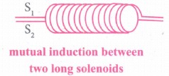
(iii) I1 is the current flowing through the solenoid S1 The magnetic field B1 produced at any point inside the solenoid S1 due to the current I1 is
\({ B }_{ 1 }={ \mu }_{ o }\frac { { N }_{ i } }{ l } { I }_{ 1 }\) ...(1)
(iv) The magnetic flux linked with each turn of S2 is equal to B1A.
Total magnetic flux linked with solenoid S2 having N2 turns is
Φ2 = \(\frac { { \mu }_{ o }{ N }_{ 1 }N_{ 2 }{ AI }_{ 1 } }{ l } \) ...(2)
But Φ2 = MI1 ...(3)
where M is the coefficient of mutual induction between S1 and S2
From equations (2) and (3),
MI1 = \(\frac { { \mu }_{ o }{ N }_{ 1 }N_{ 2 }{ AI }_{ 1 } }{ l } \); M = \(\frac { { \mu }_{ o }{ N }_{ 1 }N_{ 2 }A }{ l } \)
(v) If the core is filled with a magnetic material of permeability μ,
M = \(\frac { { \mu }_{ o }{ N }_{ 1 }N_{ 2 }A }{ l } \)
50.
Applying kirchhoff's law (loop rule) for loop ABEFA, (since current is reversed, negative sing on both sides)
= R1 x 0 - 3 x I1 - 2I1 = -6-3-1
= 3I1 - 2I1= -10
= 5I1 = -10
I1 = 2A
for loop BCDEB
= R x I1 - R1 x 0 = -4 + 3
= I1R = 1
\(R=\cfrac { 1 }{ 2 } \Omega \)
Potential difference between A and D through path ABCD is
= 6-4 + VAD = I1R
= 10 + VAD = -2 x \(\cfrac { 1 }{ 2 } \)
= 10 + CAD = -1
VAD = -9 Volt
51.
(i) If two points in a conductor are at different temperatures, the density of electrons at these points will differ and as a result the potential difference is created between these points. Thomson effect is also reversible.
(ii) Heat is transferred due to the current flow in the direction of the current. It is called positive Thomson effect. Similar effect is observed in metals like silver, zinc, and cadmium.
(iii) Heat is transferred due to the current flow in the direction opposite to the direction of current. It is called negative Thomson effect. Similar effect is observed in metals like platinum, nickel, cobalt, and mercury.
52.
i) Let I be current flowing in infinite length of conductor.
ii) Amperian loop is constructed in the form of a circular shape at a distance r from the centre of the conductor.
iii) dl is the line element along the loop.
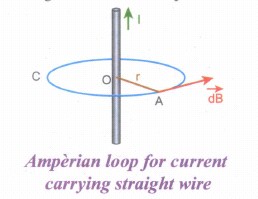
From the Ampere's law \(\oint _{ C }^{ }{ \vec { B } .\vec { dl } } \) = μoI
Hence, the angle between magnetic field vector and line element is zero. Therefore, Here, the angle between magnetic field vector and line element is zero.
\(\oint _{ C }^{ }{ {B dl } } \) = μoI
For a circular loop, the circumference is 2πr, which implies,
B\(\int _{ 0 }^{ 2\pi r }{ dl } \) = μoI
\(\vec { B } \).2πr = μoI
B = \(\frac { { \mu }_{ 0 }I }{ 2\pi r } \)
In vector form, the magnetic field is
\(\vec { B } =\frac { { \mu }_{ 0 }I }{ 2\pi r } \hat { n } \)
where \(\hat { n } \) is the unit vector along the tangent to the Amperian loop as shown in the Figure.
53.
(i) Power of a circuit is defined as the rate of consumption of electric energy in that circuit. It is given by the product of the voltage and current.
In an AC circuit, the voltage and current vary continuously with time. Let us first calculate the power at an instant and then it is averaged over a complete cycle.
(ii) The alternating voltage and alternating current in the series inductive RLC circuit at an instant are given by
v=Vm sinωt and i=Im=(ωωt+\(\phi \))t+\(\phi \))
(iii) where \(\phi \) is the phase angle between v and i. The instantaneous power is then written as
P=vi =VmIm sinωt sin(ωt + \(\phi \))
=VmIm sinωt [sin ωt cos\(\phi \) - cosωt sin\(\phi \)]
P=VmIm [cos\(\phi \) sin2ωt - sinωt cosωt sin\(\phi \)] ....(1)
(iv) Here the average of sin2ωt over a cycle is\(\frac{1}{2}\)and that of sin ωt cos ωt is zero. Substituting these values, we obtain average power over a cycle.
Pav =VmIm cos\(\phi \) x \(\frac { 1 }{ 2 } \)
=\(\frac { { V }_{ m } }{ \sqrt { 2 } } \frac { { I }_{ m } }{ \sqrt { 2 } } cos\phi\)
Pav = VRMS IRMS cos\(\phi \) ....(2)
(v) where VRMS IRMS is called apparent power and cos\(\phi \) is power factor. The average power of an AC circuit is also known as the true power of the circuit.
Special Cases:
(i) For a purely resistive circuit, the phase angle between voltage and current is zero and cos\(\phi \)=1
∴ Pav =VRMS IRMS
(ii) For a purely inductive or capacitive circuit, the phase angle is ± \(\frac { \pi }{ 2 } \) and cos\(\left( \pm \frac { \pi }{ 2 } \right) \)=0
∴ Pav =0
(iii) For series RLC circuit, the phase angle
\(\phi \) =tan-1\(\left( \frac { { X }_{ L }-{ X }_{ C } }{ R } \right) \)
∴ Pav =VRMS IRMS cos\(\phi \)
(iv) For series RLC circuit at resonance, the phase angle is zero and cos\(\phi \)=1
∴ Pav =VRMS IRMS
54.
(i) Consider a circuit containing a pure inductor of inductance L connected across an alternating voltage source (Figure). The alternating voltage is given by the equation.
v = Vm sin ωt .......(1)
(ii) The alternating current flowing through the inductor induces a self-induced emf or back emf in the circuit. The back emf is given by
Back emf, ε = \(-L\frac{di}{dt}\)
By applying Kirchoff's loop rule to the purely inductive circuit, we get
v + ε =0
Vm sin ωt = L \(\frac{di}{dt}\)
di = \(\frac{V_m}{L}\) sin ωt dt
Integrating both sides, we get
i = \(\frac{V_m}{L}\) ഽ sin ωt dt
i = \(\frac{V_m}{L_ω}\) (-cos ωt) + constant
.JPG)
(iii) The integration constant in the above equation is independent of time. Since the voltage in the circuit has only time dependent part, we can set the time independent part in the current (integration constant) into zero.
\(i=\frac { { V }_{ m } }{ \omega L } { sin }\left( \omega t-\frac { \pi }{ 2 } \right) \) \(\left[ -{ cos\omega t=-sin\left( \frac { \pi }{ 2 } -\omega t \right) }\\ \because =sin\left( \omega t-\frac { \pi }{ 2 } \right) \right] \)
(or) \(i={ I }_{ m }sin\left( \omega t-\frac { \pi }{ 2 } \right) \) .....(2)
(iv) Where \(\frac { { V }_{ m } }{ \omega L } \) = Im the peak value of the alternating current in the circuit. From equation (1) and (2), it is evident that - current lags behind the applied voltage \(\frac { \pi }{ 2 } \) in an inductive circuit. This fact is depicted in the phasor diagram. In the wave diagram also, it is seen that current lags the voltage by 90° .
(v) Inductive reactance XL:
The peak value of current Im is given by Im = \(\frac { { V }_{ m } }{ \omega L } \). Let us compare this equation with Im = \(\frac { { V }_{ m } }{ R} \) from resistive circuit The quantity ωL plays the same role as the resistance in resistive circuit. This is the resistance offered by the inductor, called inductive reactance (XL) It is measured in ohm.
XL = ωL
.JPG)
55.
(i) Consider a closed circuit consisting of a coil C of insulated wire and a galvanometer G. The galvanometer does not indicate deflection as there is no electric current in the circuit.
(ii) When a bar magnet is inserted into the stationary coil, with its north pole facing the coil, there is a momentary deflection in the galvanometer. This indicates that an electric current is set up in the coil. If the magnet is kept stationary inside the coil, the galvanometer does not indicate deflection.
(iii) The bar magnet is now withdrawn from the coil, the galvanometer again gives a momentary deflection but in the opposite direction. So, the electric current flows in opposite direction. Now if the magnet is moved faster, it gives a larger deflection due to a greater current in the circuit.
(iv) The ar magnet is reversed, i.e., the south pole now faces the coil. When the above experiment is repeated, the deflections are opposite to that obtained in the case of north pole.
(v) If the magnet is kept stationary and the coil is moved towards or away from the coil, similar results are obtained. It is concluded that whenever there is a relative motion between the coil and the magnet, there is deflection in the galvanometer, indicating the electric current setup in the coil.

12th Standard Syllabus & Materials
12th Standard
TN 12th Computer Applications களப்பெயர் முறைமை (DNS) Sample Question Papers Study Material - QB365 Set A
NEW12th Standard
TN 12th Computer Applications வலையமைப்பு எடுத்துக்காட்டுகள் மற்றும் நெறிமுறைகள் Sample Question Papers Study Material - QB365 Set A
NEW12th Standard
TN 12th Computer Applications கணினி வலையமைப்பு ஓர் அறிமுகம் Sample Question Papers Study Material - QB365 Set A
NEW12th Standard
TN 12th Computer Applications PHP-உடன் MySQL-ஐ இணைத்தல் Sample Question Papers Study Material - QB365 Set A



Tamilnadu Stateboard 12th Standard Subjects

Maths

Chemistry
Physics

Biology

Computer Science

Business Maths and Statistics

Economics

Commerce

Accountancy

History

Computer Applications
Biology
Computer Technology
Computer Applications
Computer Science
Business Maths and Statistics
Commerce
Economics
Maths
Chemistry
Physics
Computer Technology
History
Accountancy

Tamil

English

French
Tamilnadu Stateboard Standards

