
 100% FREE ACCESS
12th Standard Syllabus & Materials
12th Standard
TN 12th Computer Applications மின்னணு தரவு பரிமாற்றம் Sample Question Papers Study Material - QB365 Set A
NEW12th Standard
TN 12th Computer Applications மின் - வணிக பாதுகாப்பு அமைப்புகள் Sample Question Papers Study Material - QB365 Set A
NEW12th Standard
TN 12th Computer Applications மின்னணு செலுத்தல் முறைகள் Sample Question Papers Study Material - QB365 Set A
NEW12th Standard
TN 12th Computer Applications மின் - வணிகம் Sample Question Papers Study Material - QB365 Set A
NEW12th Standard
TN 12th Computer Applications திறந்த மூல கருத்துருக்கள் Sample Question Papers Study Material - QB365 Set A
NEW12th Standard
TN 12th Computer Applications வலையமைப்பு வடமிடல் Sample Question Papers Study Material - QB365 Set A

Published on: 02/09/2020
12th Standard Physics English Medium Sample 3 Mark Book Back Questions (New Syllabus) 2020
Download Tamil Nadu 12th Standard Physics question papers, model tests, one-mark questions, important questions, and public exam papers in PDF format. Free study materials and answer keys for TN State Board students.
Questions + Answers key
Take MCQ Physics Test1.
A monochromatic light is incident on an equilateral prism at an angle 30o and is emergent at an angle of 75o . What is the angle of deviation produced by the prism?
2.
Light travelling through transparent oil enters in to glass of refractive index 1.5. If the refractive index of glass with respect to the oil is 1.25, what is the refractive index of the oil?
3.
Calculate the radius of \(_{ 79 }^{ 197 }{ Au }\) Au nucleus.
4.
The self-inductance of an air-core solenoid is 4.8 mH. If its core is replaced by iron core, then its self-inductance becomes 1.8 H. Find out the relative permeability of iron.
5.
A circular antenna of area 3 m2 is installed at a place in Madurai. The plane of the area of antenna is inclined at 47o with the direction of Earth’s magnetic field. If the magnitude of Earth’s field at that place is 4.1 x 10⁻⁵ T find the magnetic flux linked with the antenna.
6.
Two materials X and Y are magnetised whose values of intensity of magnetisation are 500 A m–1 and 2000 A m–1 respectively. If the magnetising field is 1000 A m–1, then which one among these materials can be easily magnetized?
7.
Let the magnetic moment of a bar magnet be \(\overset { \rightarrow }{ { p }_{ m } } \) whose magnetic length is d = 2l and pole strength is qm. Compute the magnetic moment of the bar magnet when it is cut into two pieces
(a) along its length
(b) perpendicular to its length.
8.
Resistance of a material at 20oC and 40oC are 45 Ω and 85 Ω respectively. Find its temperature coefficient of resistivity.
9.
A potential difference across 24 Ω resistor is 12 V. What is the current through the resistor?
10.
Calculate the number of electrons in one coulomb of negative charge.
11.
Elaborate any two types of Robots with relevant examples.
12.
Derive the energy expression for an electron is the hydrogen atom using Bohr atom model.
13.
Compare the electromagnetic oscillations of LC circuit with the mechanical oscillations of blockspring system qualitatively to find the expression for angular frequency of LC oscillator.
14.
Obtain an expression for motional emf from Lorentz force.
15.
Explain in detail Coulomb’s law and its various aspects.
16.
Show the time period of oscillation when a bar magnet is kept in a uniform magnetic field is \(T=2\pi \sqrt { \frac { 1 }{ { p }_{ m }B } } \) in second, where I represents a moment of inertia of the bar magnet, pm is the magnetic moment and B is the magnetic field.
17.
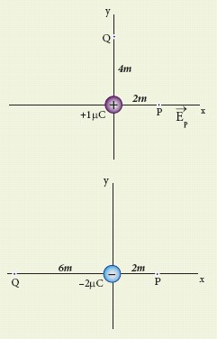
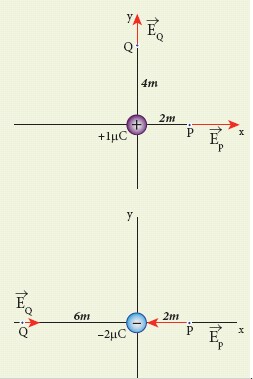
Calculate the electric field at points P, Q for the following two cases, as shown in the figure.
(a) A positive point charge +1 μC is placed at the origin.
(b) A negative point charge -2 μC is placed at the origin.
18.
Briefly explain the principle and working of electron microscope.
19.
Explain how frequency of incident light varies with stopping potential.
20.
State Boolean laws. Elucidate how they are used to simplify Boolean expressions with suitable example.
21.
Explain the construction and working of a full wave rectifier
22.
Discuss about the simple microscope and obtain the equations for magnification for near point focusing and normal focusing.
23.
Derive the equation for effective focal length for lenses in out of contact
24.
Describe the working of nuclear reactor with a block diagram.
25.
Explain the basic elements of communication system with the necessary block diagram.
26.
Explain the principle and working of a moving coil galvanometer.
27.
Obtain a relation for the magnetic field at a point along the axis of a circular coil carrying current using Biot-Savart law.
28.
How are the three different emfs generated in a three-phase AC generator? Show the graphical representation of these three emfs.
29.
Explain the Maxwell’s modification of Ampere’s circuital law.
30.
Discuss the various properties of conductors in electrostatic equilibrium.
31.
1.
Since, the prism is equilateral, A = 60o;
Given, i1 = 30o;i2 = 75o
Equation for angle of deviation, d = i1 + i2 – A
Substituting the values, d = 30°+ 75°– 60°= 45°
The angle of deviation produced d = 45o
2.
Given, ngo = 1.25 and ng = 1.5
Refractive index of glass with respect to oil,
\({ n }_{ go }=\cfrac { { n }_{ g } }{ { n }_{ 0 } } \)
Rewriting for refractive index of oil,
\({ n }_{ p }=\cfrac { { n }_{ g } }{ { n }_{ go } } =\cfrac { 1.5 }{ 1.25 } =1.2\)
The refractive index of oil is, no = 1.2
3.
R = R0A\(\frac13\)
R = 1.2 x 10−15 x (197)\(\frac13\) = 6.97 x 10⁻¹⁵ m
Or R = 6.97 F
4.
Lair = 4.8 x 10⁻³H
Liron = 1.8H
Lair = \(\mu_{o}\)n2Al = 4.8 x 10⁻³H
Liron = \(\mu_{o}\)n2Al = \(\mu_{o}\mu_r\)n2Al = 1.8H
\(\therefore { \mu }_{ r }=\frac { { L }_{ iron } }{ { L }_{ air } } =\frac { 1.8 }{ 4.8\times { 10 }^{ -3 } } =375\)
5.
B = 4.1 x 10⁻⁵ T; θ = 90o – 47o = 43° ;
A = 3m2
We know that \(\Phi_{B}=B A \cos \theta\)
\(\Phi_{\mathrm{B}}\) = 4.1 x 10–5 x 3 x cos 43o
= 4.1 x 10–5 x 3 x 0.7314
= 89.96 \(\mu \mathrm{Wb}\).
6.
The susceptibility of material X is
Xm,x = \(\frac { \left| \overset { \rightarrow }{ M } \right| }{ \left| \overset { \rightarrow }{ H } \right| } =\frac { 500 }{ 1000 } =0.5\)
The susceptibility of material Y is
Xm,y = \(\frac { \left| \overset { \rightarrow }{ M } \right| }{ \left| \overset { \rightarrow }{ H } \right| } =\frac { 2000 }{ 1000 } =2\)
Since, susceptibility of material Y is greater than that of material X, material Y can be easily magnetized than X.
7.
(a) a bar magnet cut into two pieces along its length:
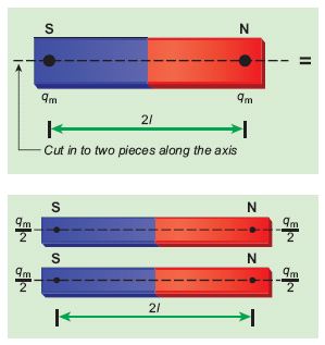
When the bar magnet is cut along the axis into two pieces, new magnetic pole strength is \({ q }_{ m }^{ ' }=\frac { { q }_{ m } }{ 2 } \) but magnetic length does not change. So, the magnetic moment is
\({ p }_{ m }^{ ' }={ q' }_{ m }2l\)
\({ p }_{ m }^{ ' }=\frac { { q }_{ m } }{ 2 } 2l=\frac { 1 }{ 2 } ({ q }_{ m }2l)=\frac { 1 }{ 2 }p_ m\)
In vector notation, \(\vec{p}'_m=\frac{1}{2}\vec{p}_m\)
(b) a bar magnet cut into two pieces perpendicular to the axis:
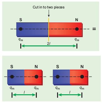
When the bar magnet is cut perpendicular to the axis into two pieces, magnetic pole strength will not change but magnetic length will be halved. So the magnetic moment is
\({ p }_{ m }^{ ' }={ q }_{ m }\times \frac { 1 }{ 2 } (2l)=\frac { 1 }{ 2 } ({ q }_{ m }.2l)=\frac { 1 }{ 2 } { p }_{ m }\)
In vector notation, \(\vec{p}'_m=\frac{1}{2}\vec{p}_m\)
8.
T0 = 20oC, T = 40oC, Ro = 45 Ω , R = 85 Ω
\(\alpha =\frac { 1 }{ { R }_{ 0 } } \frac { \Delta R }{ \Delta T } \)
\(\alpha=\frac{1}{45}\left(\frac{85-45}{40-20}\right)=\frac{1}{45}(2)\)
\(\alpha=0.044 \text { per }^{\circ} C\)
9.
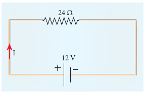
V = 12 V and R = 24 Ω
Current, I = ?
From Ohm’s law, \(I=\frac{V}{R}=\frac{12}{24}=0.5A\)
10.
According to the quantisation of charge
q = ne
Here q = 1C. So the number of electrons in 1 coulomb of charge is
n = \(\frac { q }{ e } =\frac { 1C }{ 1.6\times 10^{ -19 } } \) = 6.25 x 10¹⁸ electrons
11.
a) Human Robot :
Robots are made to resemble humans in appearance and replicate the human activities like walking, lifting, and sensing, etc.
The important part of human Robots are :
(i) Power conversion unit : Robots are powered by batteries, solar power, and hydraulics.
(ii) Actuators: It converts energy into movement. The majority of the actuators produce rotational or linear motion.
(iii) Pneumatic Air Muscles : They are devices that can contract and expand, when air is pumped inside.
(iv) Muscle wires : They are thin strands of wire made of shape memory alloys. They can contract by 5% when electric current is passed through them.
(v) Sensors: Generally used in task environments as it provides information of real-time knowledge.
(vi) Electric motors : Different types of motors are used. The most often used ones are AC motor, Brushed DC motor, Brushless DC motor, Geared DC motor etc,. They are used to actuate the parts of the robots like wheels, arms, fingers, legs, sensors, camera, weopons, systems, etc.
(vii) Robot locomotion : It provides different types of movement to the Robot. They are,
(a) Legged.
(b) Wheeled.
(c) Combination of Legged and Wheeled Locomotion.
(d) Tracked slip/skid.
(viii) Controller : lt is known as the "brain" which is run by a computer program. It gives commands for the moving parts to perform the job.
(vi) Piezo Motors and Ultrasonic Motors : It is used for industrial robots.
(x) Artificial Intelligence : The artificial intelligence is introduced into robots to bring in human like behavior in robots. Now they work on,
(a) Face recognition.
(b) Providing response to player's actions in computer games.
(c) Taking decisions based on previous actions.
(d) To regulate the traffic by analyzing the density of traffic on roads.
(e) Translate words from one language to another.
b) Industrial Robots :
There are six types of industrial robots.
(i) Cartesian.
(ii) Selective Compliance Assembly Robot Arm (SCARA).
(iii) Cylindrical.
(iv) Delta.
(v) Polar.
(vi) Vertically articulated.
Again six-axis robots are ideal for Are Welding, Spot Welding, Material Handling and Machine Tending and other applications. They can work for 24 x 7, stronger and faster than humans. However, humans cannot be replaced by robots in decision making.
12.
The electrostatic force is a conservative force, the potential energy for the electron in nth orbit is
\(U_{n} =\frac{1}{4 \pi \varepsilon_{0}} \frac{(+Z e)(-e)}{r_{n}}=-\frac{1}{4 \pi \varepsilon_{0}} \frac{Z^{2}}{r_{n}} \) \(\left[ \because r_n=\frac{\varepsilon_{0} h^{2} n^{2}}{\pi m Z e^{2}}\right]\)
\(U_{n} =-\frac{1}{4\varepsilon_{0}} -\frac{Z^{2} \mathrm{me}^{4}}{h^{2} n^{2}} \)
The kinetic energy of electron in nth orbit is
\(\mathrm{KE}_{\mathrm{n}}=\frac{1}{2} \mathrm{mv}_{\mathrm{n}}^{2}=\frac{\mathrm{Z}^{2} m \mathrm{e}^{4}}{8 \varepsilon_{0}^{2} \mathrm{~h}^{2} \mathrm{n}^{2}}\)
This implies that Un = -2KEn
Total energy of electron in the nth orbit is
\(E_{n}=K E_{n}+U_{n}=K E_{n}-2 K E_{n}=-K E_{n} \)
\(E_{n}=-\frac{Z^{2} m e^{4}}{8 \varepsilon_{0}^{2} h^{2} n^{2}} \)
For Hydrogen atom Z = 1
\(E_{n}=-\frac{m e^{4}}{8 \varepsilon_{0}^{2} h^{2} n^{2}} \text { joule }\)
n - principal quantum number
The negative sign indicates that the electron is bound to the nucleus.
Substituting the values of mass and charge of an electron (m and e), permittivity of free space \(\varepsilon^{0}\) and Planck's constant h and expressing in terms of (+(eV)), we get
\(E_{n}=-13.6\left(\frac{1}{n^{2}}\right) e V\)
(i) For the first orbit (ground state), the total energy of electron is E1 = - 13.6 eV.
(ii) For the second orbit (first excited state), the total energy of electron is E2 = -3.4 eV.
(iii) For the third orbit (second excited state), the total energy of electron is E3 = -1.51 eV and so on.
13.
Qualitative treatment:
The electromagnetic oscillations of LC system can be compared with the mechanical oscillations of a spring-mass system.
There are two forms of energy involved in LC oscillations. One is electrical energy of the charged capacitor, the other magnetic energy of the inductor carrying current.
Table: Energy in two oscillatory systems:
| LC oscillator | Spring-mass system | ||
| Element | Energy | Element | Energy |
| Capacitor | Electrical Energy \(=\frac{1}{2}\left(\frac{1}{\mathrm{C}}\right) q^{2}\) | Spring | Potential energy\(\frac{1}{2} k x^{2}\) |
| Inductor | Magnetic energy \(=\frac{1}{2} \mathrm{~Li}^2, i=\frac{dq}{dt}\) | Mass | Kinetic energy\(=\frac{1}{2} m v^{2},v=\frac{dx}{dt} \) |
Likewise, the mechanical energy of the spring-mass system exists in two forms; the potential energy of the compressed or extended spring and the kinetic energy of the mass. The Table lists these two pairs of energy.
By examining the table, the analogies between the various quantities can be understood and these correspondences are given in the Table.
The angular frequency of oscillations of a spring-mass is given by,
\(\omega= \sqrt \frac{k}{m}\)
From Table, k→ 1/C and m → L. Therefore, the angular frequency of LC oscillations is given by,
\(\omega= \frac{1} {\sqrt {LC}}\)
14.
(i) Consider a straight conducting rod AB of length I in a uniform magnetic field \(\vec { B } \) which is directed perpendicularly into the plane of the paper.
(ii) The length of the rod is normal to the magnetic field. Let the rod move with a constant velocity \(\vec { v } \) towards right side
(iii) When the rod moves, the free electrons present in it also move with same velocity \(\vec { v } \) in \(\vec { B } \). As a result, the Lorentz force acts on free electrons in the direction from B to A and is given by the relation
.JPG)
\({ \vec { F } }_{ B }=-e(\vec v\times \vec { B } )\)
(iv) The action of this Lorentz force is to accumulate the free electrons at the end A. This accumulation of free electrons produces a potential difference across the rod which in turn establishes an electric field \(\vec { E } \) directed along BA
(v) Due to the electric field \(\vec { E } \), the coulomb force starts acting on the free electrons along AB and is given by
\({ \vec { F } }_{ E }=-e\vec { F } \)
(vi) The magnitude of the electric field \(\vec { E } \) keeps on increasing as long as accumulation of electrons at the end A continues. The force \({ \vec { F } }_{ E }\) also increases until equilibrium is reached.
(vii) At equilibrium, the magnetic Lorentz force \({ \vec { F } }_{ B }\) and the coulomb force \({ \vec { F } }_{ E }\) balance each other and no further accumulation of free electrons at the end A takes place.
| \(\left| { \vec { F } }_{ B } \right| =\left| { \vec { F } }_{ E } \right| \) \(\left| -e(\vec { v } \times \vec { B } ) \right| =\left| -e\vec { E } \right| \) vB Sin 900 = E ⇒vB = E |
The potential difference between two ends of the rod is
V = El
V = vBl
Thus, the Lorentz force on the free electrons is responsible to maintain this potential difference and hence produces an emf
ε = Blv
As this emf is produced due to the movement of the rod, it is often called as motional emf. If the ends A and B are connected by an external circuit or total resistance R, then current \(i=\frac {ε}{R}=\frac{Blv}{R}\)flows in it. The direction of the current is found from right-hand thumb rule.
15.
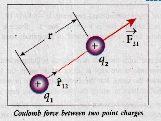
(i) Consider two point charges q1 and q2 at rest in vacuum, and separated by a distance of r, as shown in the figure.
(ii) According to Coulomb, the force on the point charge q2 exerted by another point charge q1 is \(\overrightarrow{F_{21}}=k \frac{q_{1} q_{2}}{r^{2}} \hat{r}_{12}\)
(iii) where \(\hat{r}_{12}\) is the unit vector directed from charge q1 to charge q2 and k is the proportionality constant.
Important aspects of Coulomb’s law
(i) Coulomb’s law states that the electrostatic force is directly proportional to the product of the magnitude of the two point charges and is inversely proportional to the square of the distance between the two point charges.
(ii) The force on the charge q2 exerted by the charge q1 always lies along the line joining the two charges. \({ \hat { r } }_{ 12 }\) is the unit vector pointing from charge q1 to q2. It is shown in the Figure. Likewise, the force on the charge q1 exerted by q2 is along \(-{ \hat { r } }_{ 12 }\)(i.e., in the direction opposite to \({ \hat { r } }_{ 12 })\).
(iii) In SI units, \(k=\frac { 1 }{ 4\pi { \varepsilon }_{ 0 } } \) and its value is k = 9 x 10⁹ Nm2C-2. Here \({ \varepsilon }_{ 0 }\) is the permittivity of free space or vacuum and the value of \({ \varepsilon }_{ 0 }=\frac { 1 }{ 4\pi k } =8.85\times { 10 }^{ -12 }{ C }^{ 2 }{ N }^{ -1 }{ m }^{ -2 }\).
(iv) The magnitude of the electrostatic force between two charges each of one coulomb and separated by a distance of 1 m is calculated as follows: \(|F|=\frac { 9\times { 10 }^{ 9 }\times 1\times 1 }{ { 1 }^{ 2 } } =9\times { 10 }^{ 9 }N\).
(v) In SI units, Coulomb's law in vacuum takes the form \({ \vec { F } }_{ 21 }=\frac { 1 }{ { 4\pi \varepsilon }_{ 0 } } \frac { { q }_{ 1 }{ q }_{ 2 } }{ { r }^{ 2 } } { \hat { r } }_{ 12 }.\) In a medium of permittivity \(\varepsilon \), the force between two point charges is given by\({ \vec { F } }_{ 21 }=\frac { 1 }{ 4\pi \varepsilon } \frac { { q }_{ 1 }{ q }_{ 2 } }{ { r }^{ 2 } } { \hat { r } }_{ 12 }\). Since \(\varepsilon \)>\(\varepsilon \)0, the force between two point charges in a medium other than vacuum is always less than that in vacuum. The relative permittivity for a given medium as \({ \varepsilon }_{ r }=\frac { \varepsilon }{ { \varepsilon }_{ 0 } } \) For vacuum or air, \(\varepsilon \)r = 1 and for all other media \(\varepsilon \)r > 1.
(vi) (a) Coulomb's law has same structure as Newton's law of gravitation. Both are inversely proportional to the square of the distance between the particles.
(b) The electrostatic force is directly proportional to the product of the magnitude of two point charges.
(c) Coulomb force between two charges can be attractive or repulsive, depending on the nature of charges and nature of the medium in which the two charges are kept at rest.
(vii) The force on a charge q1 exerted by a point charge q2 is given by
\({ \vec { F } }_{ 12 }=\frac { 1 }{ { 4\pi \varepsilon }_{ 0 } } \frac { { q }_{ 1 }{ q }_{ 2 } }{ { r }^{ 2 } } { \hat { r } }_{ 21 }\)
Here \({ \hat { r } }_{ 21 }\) is the unit vector from charge q2 to q1.
But \({ \hat { r } }_{ 21 }=-{ \hat { r } }_{ 12 },\)
\({ \vec { F } }_{ 12 }=\frac { 1 }{ { 4\pi \varepsilon }_{ 0 } } \frac { { q }_{ 1 }{ q }_{ 2 } }{ { r }^{ 2 } } \left( -{ \hat { r } }_{ 21 } \right) =\frac {- 1 }{ { 4\pi \varepsilon }_{ 0 } } \frac { { q }_{ 1 }{ q }_{ 2 } }{ { r }^{ 2 } } \left( { \hat { r } }_{ 12 } \right) \)
or \({ \vec { F } }_{ 12 }=-{ \vec { F } }_{ 21 }\)
Therefore, the electrostatic force obeys Newton's third law.
(viii) Coulomb force is true only for point charges. In fact, Coulomb discovered his law by considering the charged spheres in the torsion balance as point charges.
Point charge : If the distance between the two charged spheres (or objects) is much greater than the radii (or sizes) of the spheres (or objects).
16.
The magnitude of deflecting torque (the torque which makes the object rotate) acting on the bar magnet will tend to align the bar magnet parallel to the direction of the uniform magnetic field \(\overset { \rightarrow }{ B } \)
\(\left| \overset { \rightarrow }{ r } \right| ={ p }_{ m }Bsin\theta \)
The magnitude of restoring torque acting on the bar magnet can be written as
\(\left| \overset { \rightarrow }{ r } \right| =I\frac { { d }^{ 2 }\theta }{ { dt }^{ 2 } } \)
Under equilibrium conditions, both magnitudes of deflecting torque and restoring torque will be equal but act in the opposite directions, which means
\(\frac { { d }^{ 2 }\theta }{ { dt }^{ 2 } } =-{ p }_{ m }Bsin\theta \)
17.
Case (a)
The magnitude of the electric field at point P is
Ep = \(\frac { 1 }{ 4\pi \varepsilon _{ 0 } } \frac { q }{ { r }^{ 2 } } =\frac { 9\times { 10 }^{ 9 }\times 1\times 10^{ -6 } }{ 4 } \)
= 2.25 x 10³ NC-1
Since the source charge is positive, the electric field points away from the charge. So the electric field at the point P is given by
\(\bar { { E }_{ p } } \) = 2.25 x 10³ NC-1
For the point Q
\(|\vec { { E }_{ Q } } |=\frac { 9\times 10^{ 9 }\times 1\times { 10 }^{ -6 } }{ 16 } \) = 0.56 x 10³ NC-1
Hence \(\vec { { E }_{ Q } } \) = 0.56 x 10³\(\hat { j } \) NC-1
Case (b)
The magnitude of the electric field at point P
\(\bar { { E }_{ p } } =\frac { kq }{ r^{ 2 } } =\frac { 1 }{ 4\pi { \varepsilon }_{ 0 } } \frac { q }{ { r }^{ 2 } } =\frac { 9\times 10^{ 9 }\times 2\times 10^{ -6 } }{ 4 } \)
= 4.5 x 10³ NC-1
Since the source charge is negative, the electric field points towards the charge. So the electric field at the point P is given by
\(\vec { E_{ p } } \) = -4.5 x 10³\(\hat { i } \)NC-1
For the point Q, \(|\vec { { E }_{ Q } } |\frac { 9\times 10^{ 9 }\times 2\times { 10 }^{ -6 } }{ 36 } \)
= 0.5 x 10³ NC-1
\(\vec { E_{ Q } } \) = 0.5 x 10³\(\hat { i } \)NC-1
At the point Q the electric field is directed along the positive x-axis.
18.
Principle:
(i) The wave nature of the electron is used in the construction of microscope called electron microscope.
(ii)The resolving power of a microscope is inversely proportional to the wavelength of the radiation used for illuminating the object under study.
(iii) Higher magnification as well as higher resolving power can be obtained by employing the waves of shorter wavelengths.
(iv) De Broglie's wavelength of electron is very much less than (a few thousand less) that of the visible light being used in optical microscopes.
(v) As a result, the microscopes employing de Broglie waves of electrons have very much higher resolving power than optical microscope.
(vi) Electron microscopes giving magnification more than 2,00,000 times are common in research laboratories.
Working:
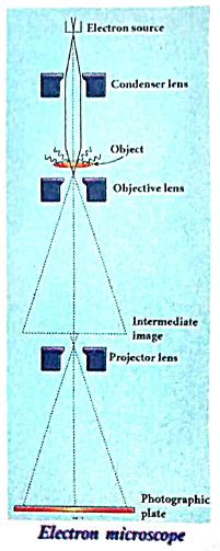
(i) The construction and working of an electron microscope is similar to that of an optical microscope except that in electron microscope focussing of electron beam is done by the electrostatic or magnetic lenses.
(ii) The electron beam passing across a suitably arranged either electric or magnetic fields undergoes divergence or convergence thereby focussing of the beam is done.
(iii) The electrons emitted from the source are accelerated by high potentials.
(iv) The beam is made parallel by magnetic condenser lens; When the beam passes through the sample whose magnified image is needed, the beam carries the image of the sample.
(v) With the help of magnetic objective lens and magnetic projector lens system, the magnified image is obtained on the screen. These electron microscopes are being used in almost all brands of science.
19.
(i) To study the effect of frequency of incident light on stopping potential, the intensity of the incident light is kept constant.
(ii) The variation of photocurrent with the collector electrode potential is studied for radiations of different frequencies and a graph drawn between them is shown in Figure From the graph, it is clear that stopping potential vary over different frequencies of incident light.
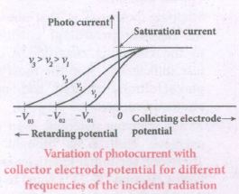
(iii) Greater the frequency of the incident radiation, larger is the corresponding stopping potential.
(iv) This implies that as the frequency is increased, the photoelectrons are emitted with greater kinetic energies so that the retarding potential needed to stop the photoelectrons is also greater.
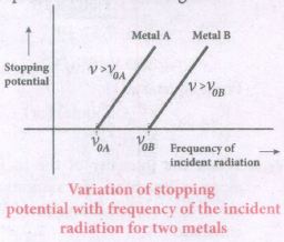
(v) Now a graph is drawn between frequent and the stopping potential for different metals (Figure).
(vi) From this graph, it is found that stopping potential varies linearly with frequency.
(vii) Below a certain frequency called their old quest no electrons are emitted; hence stopping potential is zero for that reason.
(viii) But as the frequency is increased above a threshold value, the stopping potential varies linearly with the frequency of incident light.
20.
Laws of Boolean algebra:
Complement law:
| A | Y=Ā |
| 0 | Y = \(\bar { 0 } \) = 1 |
| 0 | Y=\(\bar { 1 } \)=0 |
The complement law can be realised as Ā = A
OR laws:
| A | B | Y=A+B |
| 0 | 0 | Y = 0 + 0 = 0 |
| 0 | 1 | Y = 0 + 1 = 1 |
| 1 | 0 | Y = 1 + 0 = 1 |
| 1 | 1 | Y = 1 + 1 = 1 |
The OR laws can be realised as:
| 1st law | A+0=A |
| 2st law | A+1=1 |
| 3st law | A+A=A |
| 4st law | A+Ā=1 |
AND law:
| A | B | Y=A.B |
| 0 | 0 | Y=0.0=0 |
| 0 | 1 | Y=0.1=0 |
| 1 | 0 | Y=1.0=0 |
| 1 | 1 | Y=1.1=1 |
The AND laws can be realised as:
| 1st law | A.0=0 |
| 2st law | A.1=A |
| 3st law | A.A=A |
| 4st law | A.Ā=0 |
The Boolean operations obey the folloWing laws:
Communtative laws:
A+B =B+A
A.B =B.A
A sociate laws:
A + (B + C) = (A + B) + C
A. (B.C) = (A.B).C
D stributive laws:
A (B + C) = AB + BC
A + BC = (A + B) (A + C)
The above laws are used to simplify complicated expressions and to simplify the logic circuitry.
21.
FuIl wave rectifier :
The positive and negative half cycles of the AC input signal pass through the full wave rectifier circuit and hence it is called the full wave rectifier
Construction:
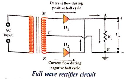
(i) It consists of two p-n junction diodes, a center-tapped transformer, and a load resistor (R1)
(ii) The centre is usually taken as the ground or zero voltage reference point.
(iii) Due to the centre tap transformer, the output voltage rectified by each diode is only one-half of the total secondary voltage.
Working:
During positive half cycle :
(i) When the positive half cycle of the ac input signal passes through the circuit, terminal M is positive, G is at zero potential and N is at negative potential.
(ii) This forward biases diode D1 and reverse biases diode D2.
(iii) Hence, being forward biased, diode D1 conducts and current flows along the path MD1AGC.
During negative half cycle:
(i) When the negative half cycle of the AC input signal passes through the circuit, terminal N becomes positive, C is at zero potential and M is at negative potential.
(ii) This forward biases diode D2 and reverse biases diode D1.
(iii) Hence, being forward biased, diode D2 conducts and current flows along the path ND2BGC.
(iii) During both positive and negative half cycles of the input signal, the current flows through the load in same direction.
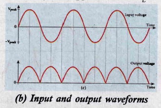
(iv) The output signal corresponding to the input signal is shown in Figure. Though both half cycles of AC input are rectified, the output is still pulsating in nature.
(v) The efficiency (η) of full wave rectifier is twice that of a half wave rectifier and is found to be 81.2 %.
22.
(i) A simple microscope is a single magnifying (converging) lens of small focal length. To get an erect, magnified and virtual image of the object.
(ii) For this the object is placed between the focal length Fand P on one side of the lens and viewed from other side of the lens. There are two magnifications to be discussed for two kinds of focusing.
(a) Near point focusing:
The eye is least strained when image is formed at near point,i.e. 25 cm. The near point is also called as least distance of distinct vision. This is shown in Figure.
.JPG)
Magnification in near point focusing:
(i) Object distance u is less than f
(ii) The image distance is the near point D. The magnification m is given by the relation,
\(m=\cfrac { v }{ u } \) ...............(1)
Substituting, V = - D and u= - u, as both the distances are measured to the left of the lens. Hence,
\(m=\cfrac { -D }{ -u }\)
\(m=\cfrac { D }{ u } \) ...............(2)
Using lens equation, W.K.T, m = 1 - (v/f)
Substiuting v = -D gives, \(\\ m=1+\cfrac { D }{ f } \) ..................(3)
This is the magnification for near point focusing.
(b) Normal focusing :
(i) The eye is most relaxed when the image is formed at infinity. The focusing is called normal focusing when the image is formed at infinity. This is shown in Figure (b).
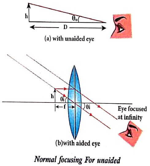
Magnification in normal focusing (angular magnification):
(ii) The angular magnification is defined as the ratio of angle θ1 subtended by the image with aided eye to the angle θ0 subtended by the object with unaided eye.
\(m=\cfrac { { \theta }_{ 1 } }{ { \theta }_{ 0 } } \) .........(2)
For unaided eye shown in Figure (a),
\(tan\theta _{ 0 }\approx { \theta }_{ 1 }=\cfrac { h }{ D } \) ................(3)
For aided eye shown in Figure(b).
\(tan\theta _{ i }={ \theta }_{ i }=\cfrac { h }{ f } \) ...................(4)
The angular magnification is,
\(m=\cfrac { { \theta }_{ i } }{ { \theta }_{ o } } =\cfrac { h/f }{ h/D } \)
\(m=\cfrac { D }{ f } \) ..............(5)
This is the magnification for normal focusing.
23.
When two thin lenses are separated by a distance d.
(i) Let 0 be a point object on the principal axis of a lens. OA is the incident rayon the lens at a point A at a height h above the optical center.
(ii) The ray is deviated through an angle ઠ and forms the image at me on the principal axis.
(iii) The incident and refracted rays subtend the angles, ∠AOP = α and ∠AIP = β with the principal axis respectively.
In the triangle ∠AOP, the angle of deviation o can be written as,
\(\delta =\alpha +\beta \) ...(1)
If the height is small as compared to PO and PI, the angles \(\alpha ,\beta \) and 0 are also small. Then,
\(\alpha \approx tan\alpha =\cfrac { PA }{ PO } ;\) and ...(2)
Then,\(\delta =\cfrac { PA }{ PO } +\cfrac { PA }{ PI } \)
Here, PA = h, PO = -u and PI = v
\(\delta =\cfrac { h }{ -u } +\cfrac { h }{ v } =h\left( \cfrac { 1 }{ -u } +\cfrac { 1 }{ v } \right) \)
After rearranging
\(\delta -h\left( \cfrac { 1 }{ v } -\cfrac { 1 }{ u } \right) =\cfrac { h }{ f } \)
\(\delta =\cfrac { h }{ f } \)
(iv) The above equation tells that the angle of deviation is the ratio of height to the focal length. Now, the case of two lenses of focal length it and 12 arranged coaxially but separated by a distance d can be considered as shown in the below Figure
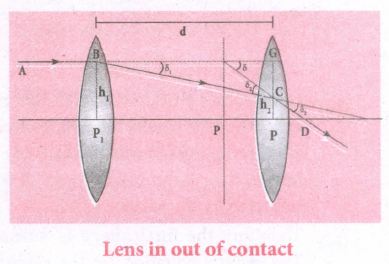
\(\delta ={ \delta }_{ 1 }+{ \delta }_{ 2 }\)
From Equation (5),
\({ \delta }_{ 1 }=\cfrac { { h }_{ 1 } }{ { f }_{ 1 } } ;{ \delta }_{ 2 }=\cfrac { { h }_{ 2 } }{ { f }_{ 2 } } \) and \(\delta =\cfrac { { h }_{ 1 } }{ f } \)
The equation (6) becomes,
\(\cfrac { { h }_{ 1 } }{ f } +\cfrac { { h }_{ 1 } }{ { f }_{ 1 } } +\cfrac { { h }_{ 2 } }{ { f }_{ 2 } } \)
From the geometry,
h2 - h1 = P2G - P2 C = CG
h2 - h1 = BG tan ઠ1≈ BGઠ1
\({ h }_{ 2- }{ h }_{ 1 }={ h }_{ 1 }d\cfrac { { h }_{ 1 } }{ { h }_{ 2 } } \)
\({ h }_{ 2 }={ h }_{ 1 }d\cfrac { { h }_{ 1 } }{ { h }_{ 2 } } \)
Substituting the above equation in Equation (8)
\(\cfrac { 1 }{ f } =\cfrac { 1 }{ { f }_{ 1 } } +\cfrac { 1 }{ { f }_{ 2 } } +\cfrac { 1 }{ { f }_{ 1 }{ f }_{ 2 } } \)
(vi) The above equation could be used to find I the equivalent focal length. To find the position of the equivalent lens, we can further write from the geometry,
\({ PP }_{ 2 }=EG=\cfrac { GC }{ tan\delta } \)
\({ PP }_{ 2 }=EG=\cfrac { GC }{ tan\delta } \)
\({ PP }_{ 2 }=EG=\cfrac { GC }{ tan\delta } =\cfrac { { h }_{ 1 }-{ h }_{ 2 } }{ tan\delta } =\cfrac { { h }_{ 1 }-{ h }_{ 2 } }{ \delta } \)
From equations (7) and (9)
\({ h }_{ 2 }-{ h }_{ 1 }=d\cfrac { { h }_{ 1 } }{ { \quad f }_{ 1 } } \) and \(\delta =\cfrac { { h }_{ 1 } }{ f } \)
\({ PP }_{ 2 }=\left( d\cfrac { { h }_{ 1 } }{ { f }_{ 1 } } \right) \times \left( \cfrac { f }{ { h }_{ 1 } } \right) \)
\({ PP }_{ 2 }=\left( d\cfrac { f }{ { f }_{ 1 } } \right) \)
24.
Nuclear reactor is a system in which the nuclear fission takes place in a self-sustained controlled manner.
The main parts of a nuclear reactor :
(a) Fuel (b) Neutron source (c) moderator (d) control rods (e) shielding (f) cooling system
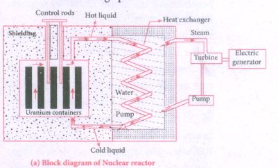
(a) Fuel:
(i) The fuel is fissionable material, usually uranium or plutonium.
(ii) Naturally occurring uranium contains only 0.7% of \(_{ 92 }^{ 235 }{ U }\) and 99.3% \(_{ 92 }^{ 238 }{ U }\).
(iii) So the fuel must be enriched such that it contains at least 2 to 4% of \(_{ 92 }^{ 235 }{ U }\).
b) Neutron Source :
(i) A neutron source is required to initiate the chain reaction for the first time.
(ii) A mixture of beryllium with plutonium or polonium is used as the neutron source.
(iii) During fission only fast neutrons are emitted. But slow neutrons are preferred for sustained nuclear reactions.
(c) Moderators :
(i) The moderator is a material used to convert fast neutrons into slow neutrons. Usually the moderators are chosen in such a way that it must be very light nucleus having mass comparable to that of neutrons.
(ii) Hence, these light nuclei undergo collision with fast neutrons and the speed of the neutron is reduced.
(iii) Most of the reactors use water, heavy water (D2O) and graphite as moderators.
(d) Control rods :
(i) The control rods are used to adjust the reaction rate.
(ii) An average of 2.5 neutrons are emitted in each fission reaction.
(iii) For the controlled chain reactions, only one effort is allowed to produce another fission and the remaining neutrons are absorbed by the control rod.
(iv) Usually cadmium or boron acts as control rod material.
(v) These rods are inserted into the uranium blocks.
(vi) Depending on the insertion depth of control rod into the uranium, the average number of the neutrons produced per fission is set to be equal to one or greater than one.
(vii) If the average number of neutrons produced per fission is equal to one, then reactor is said to be in critical state.
(viii) If it is greater than one, then reactor is said to be in super-critical and it may explode sooner of may cause massive destruction.
(e) Shielding :
For a protection against harmful radiation, the nuclear reactor is surrounded by a concrete wall of thickness of about 2 to 2.5 m.
(f) Cooling system :
(i) The cooling system removes the heat generated in the reactor core.
(ii) Ordinary water, heavy water and liquid sodium are used as coolant.
(iii) They have very high specific heat capacity and have large boiling point under high pressure.
(iv) This coolant passes through the fuel block and carries away the heat to the steam generator through heat exchanger.
(v) The steam runs the turbines which produces electricity in power reactors.
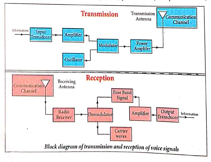
25.
a) Information (Baseband or input signal):
i) Information can be in the form of a sound signal like speech, music, pictures, or computer data which is given as input to the input transducer.
b) Input transducer:
i) It converts the information which is in the form of sound, music, pictures or computer data into corresponding electrical signals.
ii) The electrical equivalent of the original information is called the baseband signal.
iii) The best example is the microphone that converts sound energy into electrical energy.
c) Transmitter
i) It feeds the electrical signal from the transducer to the communication channel
ii) It consists of circuits such as amplifier, oscillator, modulator, and power amplifier.
iii) Amplifier: The transducer output is very weak and is amplified by the amplifier.
iv) Oscillator: It generates high-frequency carrier wave (a sinusoidal wave) for long distance transmission into space. As the energy of a wave is proportional to its frequency, the carrier wave has very high energy.
v) Modulator: It superimposes the baseband signal onto the carrier signal and generates the modulated signal.
vi) Power amplifier: It increases the power level of the electrical signal in order to cover a large distance.
d) Transmitting antenna:
i) It radiates the radio signal into space in all directions.
ii) It travels in the form of electromagnetic waves with the speed of light.
e) Communication channel:
Communication channel is used to carry the electrical signal from transmitter to receiver with less noise or distortion.
Example: Wires, cables, optical fibres in wireline communication and free space in wireless communication.
f) Receiver:
i) The signals that are transmitted through the communication medium are received with the help of a receiving antenna and are fed into the receiver.
ii) The receiver consists of electronic circuits like demodulator, amplifier, detector etc. The demodulator extracts the baseband signal from the carrier signal.
iii) Then the baseband signal is detected and amplified using amplifiers.
iv) Finally, it is fed to the output transducer.
g) Repeaters:
i) Repeaters are used to increase the range or distance through which the signals are sent.
ii) It is a combination of transmitter and receiver.
iii) The signals are received, amplified, and retransmitted with a carrier signal of different frequency to the destination.
iv) The best example is the communication satellite in space
h) Output transducer:
i) It converts the electrical signal back to its original form such as sound, music, pictures or data.
ii) Examples of output transducers are loudspeakers, picture tubes, computer monitor, etc
26.
Principle : When a current carrying loop is placed in a uniform magnetic field it experiences a torque.
Construction : A moving coil galvanometer consists of a rectangular coil PQRS of insulated thin copper wire. The coil contains a large number of turns wound over a light metallic frame. A cylindrical soft-iron core is placed symmetrically inside the coil as shown in Figure. The rectangular coil is suspended freely between two pole pieces of a horse-shoe magnet.
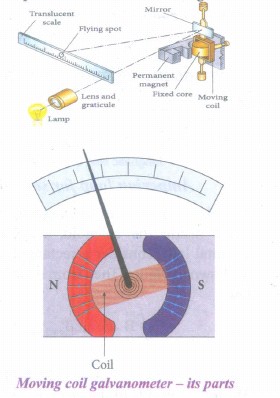
The upper end of the rectangular coil is attached to one end of fine strip of phosphor bronze and the lower end of the coil is connected to a hair spring which is also made up of phosphor bronze. In a fine suspension strip, a small plane mirror is attached in order to measure the deflection of the coil with the help of lamp and scale arrangement. The other end of the mirror is connected to a torsion head. In order to pass electric current through the galvanometer, the suspension strip and the spring S are connected to terminals.
Working : Consider a single turn of the rectangular coil PQRS whose length be l and breadth b. PQ = RS = l and QR = SP = b.
Let I be the electric current flowing through the rectangular coil PQRS as shown in Figure. The horse-shoe magnet has hemi - spherical magnetic poles which produces a radial magnetic field. Due to this radial field, the sides QR and SP are always parallel to the magnetic field B and experience no force. The sides PQ and RS are always parallel to the magnetic field and experience force in opposite directions. Due to this, torque is produced.
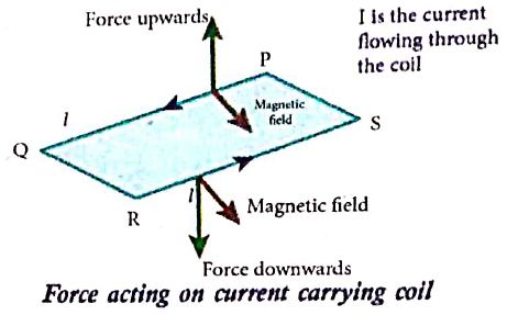
For single turn, the deflection torque is,
て = bF = bBIl = (lb)BI
て = ABI
since, area of the coil A = lb
For coil with N turns, we get
て = NABI ........(1)
Due to this deflecting torque, the coil gets twisted and restoring torque (also known as restoring couple) is developed. Hence the moment of restoring couple is proportional to the amount of twist θ. Thus
て = Kθ ............(2)
where K is the restoring couple per unit twist or torsional constant of the spring.
At equilibrium, the deflection couple is equal to the restoring couple. Therefore by comparing equations (1) and (2), we get,
NABI = Kθ
⇒ I =\(\frac { K }{ NAB } \) θ ...........(3)
(or) I = Gθ
where G = \(\frac { K }{ NAB } \) is called galvanometer constant or current reduction factor of the galvanometer.
Since, suspended moving coil galvanometer is very sensitive, we have to handle with high care while doing experiments. Most of the galvanometer we use are pointer type moving coil galvanometer.
27.
(i) Let 'R' be the radius of a current carrying circular loop.
(ii) I be the current flowing through the wire.
(iii) Let P be a point on the axis of the circular coil at a distance z from its centre 'O'
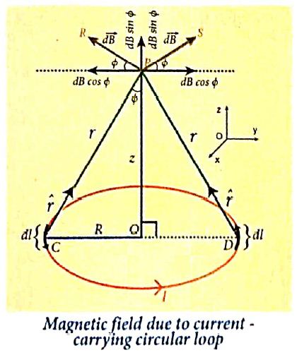
(iv) Take two diametrically opposite element \(\vec { dl } \) at C and D. According to Biot-Savart's law, the magnetic field at P due to the current element at C is
\(d \vec{B}=\frac{\mu_0}{4 \pi} \frac{I d \vec{l} \times \hat{r}}{r^2}\)
The magnitude of \( { d\vec B } \)is
\(d \vec{B}=\frac{\mu_0}{4 \pi} \frac{I d l \sin \theta}{r^2}=\frac{\mu_0}{4 \pi} \frac{I d l}{r^2}\)
where θ is the angle between \(I\vec { dl } \) and \(\vec { r } \). Here, θ = 90o.
\(\vec{B} =\int d \vec{B}=\int d B \sin \phi \hat{k} \)
\(\vec{B} =\frac{\mu_o I}{4 \pi} \int \frac{d l}{r^2} \sin \phi \hat{k} \)
\(\text {But, } \cos \theta =\frac{R}{\left(R^2+z^2\right)^{\frac{1}{2}}} \text { (using Pythagoras theorem) }\)
From ΔOCP
\(\sin \phi=\frac{R}{\left(R^2+z^2\right)^{1 / 2}} \text { and } r^2=R^2+z^2.\)
Substituting these in the above equation, we get,
\(\vec{B}=\frac{\mu_0 I}{4 \pi} \frac{R}{\left(R^2+z^2\right)^{3 / 2}} \hat{k}\left(\int d l\right)\)
If we integrate the line element from 0 to 2πR, we get the net magnetic field \(\vec{B}\) at any point P due to the current - carrying circular loop,
\(\vec{B}=\frac{\mu_0 I}{2} \frac{R^2}{\left(R^2+z^2\right)^{3 / 2}} \hat{k}\)
If the circular coil contains N turns, then the magnetic field is
\(\vec{B}=\frac{\mu_0 N I}{2} \frac{R^2}{\left(R^2+z^2\right)^{3 / 2}} \hat{k}\)
The magnetic field at the centre of the coil is,
\(\vec{B}=\frac{\mu_0NI}{2R}\hat k\) since z= 0
28.
(i) In some AC generators may have more than one coil in the armature core and each coil producesan alternating emf. In these generators, more than one emf is produced. Thus, they are called poly-phase generators.
(ii) If there are two alternating emfs produced in a generator, it is called two-phase generator, it is called two-phase generator. In some AC generators, there are three separate coils, which owould give three separate emfs. Hence, they are called three-phase AC generators.
(iii) In the simplified construction of three-phase AC generator, the armature core has 6 slots, cut on its inner rim. Each slot is 60° away from one another. Six armature conductors are mounted in these slots.The conductors 1 and 4 are joined in series to form coil 1. The conductors 3and 6 form coil 2 while the conductors 5 and 2 form coil 3. So, these coils arerectangular in shape and are 120° apart from one another.
(iv) The initial position of the field magnet is horizontal and field direction is perpendicular to the plane of the coil 1. As it is seen in single phase AC generator, when field magnet is rotated from that position in clockwise direction, alternating emf ε1 in coil 1 begins a cycle from origin O. This is shown in Figure.
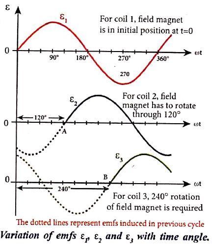
(v) The corresponding cycle for alternating emf ε2 in coil 2 starts at point A after field magnet has rotated through 120°. Therefore, the phase difference between ε1 and ε2 is 120°. Similarly, emf ε3 in coil 3 would begin its cycle at point B after 240° rotation of field magnet from initial position. Thus these emfs produced in the three phase AC generator have 120° phase difference between one another.
29.
(i) We have stated Ampere's law as \(\oint \vec{B} \cdot \overrightarrow{d l}=\mu_oi\)
(ii) Where, i is the electric current crossing a surface bounded by a closed curve and the line integral of \(\vec{B}\) is calculated along that closed curve. This equation is valid only when the electric field at the surface does not change with time.
(iii) Maxwell strongly believed that when the time varying magnetic field produces an electric field, the time varying electric field must produce a magnetic field.
(iv) To understand how a varying electric field produces magnetic field, let us consider a situation of charging a parallel plate capacitor.
.JPG)
(v) Let ic be the conduction current. To calculate the magnetic field at P (fig. 1 ) an amperian loop. S1 is drawn. Applying Ampere circuital law for the surface S1, we get
\(\oint \vec{B} \cdot \overrightarrow{d l}=\mu_0 i_c\) Where, \(\mu_0\) is permeability of free space.
(vi) Applying the same for the surface S2, we get \(\oint \vec{B} \cdot \overrightarrow{d l}=0.\)
Because the surface S2 nowhere touches the wire carrying conduction current. Therefore for the point P at one surface (S1) it has some value and at another surface (S2) it has zero value.
(vii) So, Maxwell believed that there must be a current associated with the changing electric field in between the capacitor and he called that current as displacement current.
(viii) Applying Gauss law to the electric flux between the plates of the capacitor \(\phi_E=\oint \vec{E} \cdot \overrightarrow{\mathrm{dA}}=E A=\frac{q}{\varepsilon_0}\) where, A is the area of the plate.
The change in electric flux is \(\frac{d \phi_F}{d t}=\frac{1}{\varepsilon_0} \frac{d q}{d t} (or) \frac{\mathrm{dq}}{\mathrm{dt}}=\mathrm{i}_{\mathrm{d}}=\varepsilon_0 \frac{\mathrm{d} \phi_{\mathrm{E}}}{\mathrm{dt}}\), where id is the displacement current.
(ix) The displacement current can be defined as the current which comes into play in the region in which the electric field and electric flux are changing with time.
(x) So, Maxwell modified Ampere's law \(\oint_{l} \vec{B} \cdot d \vec{l}=\mu_{0} i_c+\mu_{0}-i_d\) which means the total current enclosed by the surface is sum of conduction current and displacement current.
30.
A conductor at electrostatic equilibrium has the following properties:
(i) The electric field is zero everywhere inside the conductor. This is true regardless of whether the conductor is solid or hollow:
(a) This is an experimental fact. Suppose the electric field is not zero inside the metal, then there will be a force on the mobile charge carriers due to this electric field.
(b) As a result, there will be a net motion of the mobile charges, which contradicts the conductors being in electrostatic equilibrium. Thus the electric field is zero everywhere inside the conductor. We can also understand this fact by applying an external uniform electric field on the conductor.
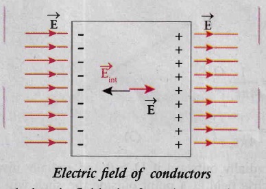
(c) Before applying the external electric field, the free electrons in the conductor are uniformly distributed in the conductor. When an electric field is applied, the free electrons accelerate to the left causing the left plate to be negatively charged and the right plate to be positively charged as shown in Figure.
(d) Due to this realignment of free electrons, there will be an internal electric field created inside the conductor which increases until it nullifies the external electric field.
(e) Once the external electric field is nullified the conductor is said to be in electrostatic equilibrium. The time taken by a conductor to reach electrostatic equilibrium is in the order of 10-16 s, which can be taken as almost instantaneous.
(ii) There is no net charge inside the conductors. The charges must reside only on the surface of the conductors:
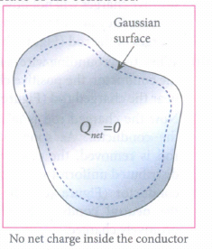
(a) We can prove this property using Gauss law. Consider an arbitrarily shaped conductor as shown in Figure. A Gaussian surface is drawn the conductor such that it is very close to the surface of the conductor.
(b) Since the electric field is zero everywhere inside the conductor, the net electric flux is also zero over this Gaussian surface. From Gauss's law, this implies that there is no net charge inside the conductor.
(c) Even if some charge is introduced inside the conductor, it immediately reaches the surface of the conductor.
(iii) The electric field outside the conductor is perpendicular to the surface of the conductor and has a magnitude of \(\frac { \sigma }{ { \varepsilon }_{ 0 } } \) is the surface charge density at that point:
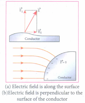
(a) If the electric field has components parallel to the surface of the conductor, then free electrons on the surface of the conductor would experience acceleration (Figure a).
(b) This means that the conductor is not in equilibrium. Therefore at electrostatic equilibrium, the electric field must be perpendicular to the surface of the conductor. This is shown in Figure (b).
(c) We now prove that the electric field has magnitude \(\frac { \sigma }{ { \varepsilon }_{ 0 } } \) just outside the conductor's surface.
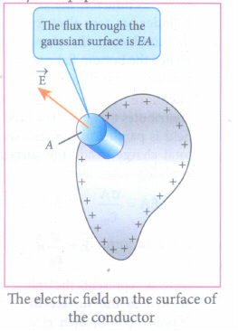
(d) Consider a small cylindrical Gaussian surface, as shown in the Figure. One-half of this cylinder is embedded inside the conductor.
(e) Since electric field is normal to the surface of the conductor, the curved part of the cylinder has zero electric flux.
(f) Also inside the conductor, the electric field is zero. Hence the bottom flat part of the Gaussian surface has no electric flux.
(g) Therefore the top flat surface alone contributes to the electric flux. The electric field is parallel to the area vector and the total charge inside the surface is σA. By applying Gaus's law,
\(EA=\frac { \sigma A }{ { \varepsilon }_{ 0 } } \)
In vector form, \(\vec { E } =\frac { \sigma }{ { \varepsilon }_{ 0 } } \hat { n } \) ....(1)
(h) Where \(\hat { n } \) represents the unit vector outward normal to the surface of the conductor. Suppose \(\sigma\) < 0, then electric field points inward perpendicular to the surface.
(iv) The electrostatic potential has the same value on the surface and inside of the conductor :
(a) We know that the conductor has no parallel electric component on the surface which means that charges can be moved on the surface without doing any work.
(b) This is possible only if the electrostatic potential is constant at all points on the surface and there is no potential difference between any two points on the surface.
(c) Since the electric field is zero inside the conductor, the potential is the same as the surface of the conductor. Thus at electrostatic equilibrium, the conductor is always at equipotential.
31.

12th Standard Syllabus & Materials
12th Standard
TN 12th Computer Applications களப்பெயர் முறைமை (DNS) Sample Question Papers Study Material - QB365 Set A
NEW12th Standard
TN 12th Computer Applications வலையமைப்பு எடுத்துக்காட்டுகள் மற்றும் நெறிமுறைகள் Sample Question Papers Study Material - QB365 Set A
NEW12th Standard
TN 12th Computer Applications கணினி வலையமைப்பு ஓர் அறிமுகம் Sample Question Papers Study Material - QB365 Set A
NEW12th Standard
TN 12th Computer Applications PHP-உடன் MySQL-ஐ இணைத்தல் Sample Question Papers Study Material - QB365 Set A



Tamilnadu Stateboard 12th Standard Subjects

Maths

Chemistry
Physics

Biology

Computer Science

Business Maths and Statistics

Economics

Commerce

Accountancy

History

Computer Applications
Biology
Computer Technology
Computer Applications
Computer Science
Business Maths and Statistics
Commerce
Economics
Maths
Chemistry
Physics
Computer Technology
History
Accountancy

Tamil

English

French
Tamilnadu Stateboard Standards

