
 100% FREE ACCESS
12th Standard Syllabus & Materials
12th Standard
TN 12th Computer Applications மின்னணு தரவு பரிமாற்றம் Sample Question Papers Study Material - QB365 Set A
NEW12th Standard
TN 12th Computer Applications மின் - வணிக பாதுகாப்பு அமைப்புகள் Sample Question Papers Study Material - QB365 Set A
NEW12th Standard
TN 12th Computer Applications மின்னணு செலுத்தல் முறைகள் Sample Question Papers Study Material - QB365 Set A
NEW12th Standard
TN 12th Computer Applications மின் - வணிகம் Sample Question Papers Study Material - QB365 Set A
NEW12th Standard
TN 12th Computer Applications திறந்த மூல கருத்துருக்கள் Sample Question Papers Study Material - QB365 Set A
NEW12th Standard
TN 12th Computer Applications வலையமைப்பு வடமிடல் Sample Question Papers Study Material - QB365 Set A

Published on: 29/09/2020
12th Standard Physics English Medium Sample 5 Mark Creative Questions (New Syllabus 2020)
Download Tamil Nadu 12th Standard Physics question papers, model tests, one-mark questions, important questions, and public exam papers in PDF format. Free study materials and answer keys for TN State Board students.
Questions + Answers key
Take MCQ Physics Test1.
A convex lens, of focal length 20 cm, has a point object placed on its principal axis at distance of 40 cm from it. A plane mirror is placed 30 cm behind the convex lens. Locate the position of image formed by this combination.
2.
A double convex lens, made from a material of refractive index μ1 is immersed in a liquid of refractive index μ2 where μ2 > μ1 What change, if any, would occur in the nature of the lens?
3.
The total magnification produced by a compound microscope is 20. The magnification produced by the eyepiece is 5. The microscope is focused on a certain object. The distance between the objective and eyepiece is observed to be 14 cm. If the least distance of distinct vision is 20 cm, calculate the focal length of the objective and the eyepiece.
4.
(a) Define the term 'intensity of radiation' in terms of photon pictures of light.
(b) Two monochromatic beams, one red and the other blue, have the same intensity. In which case
(i) the number of photons per unit area per second is larger,
(ii) the maximum kinetic energy of the photoelectrons is more? Justify your answer.
5.
Plot a graph showing the variation of del Broglie wavelength λ versus \(\frac { 1 }{ \sqrt { V } } \) , where V is accelerating the potential for two particles A and B carrying the same charge but of masses m1, m2 (m1 > m2). Which one of the two represents a particle of smaller mass and why?
6.
Calculate the de Broglie wavelength of a neutron of kinetic energy 150 eV. Mass of neutron = 1.67 x 10⁻²⁷ kg.
7.
Write briefly the underlying principle used in Davison-Germer experiment to verify wave nature of electrons experimentally. What is the de-Broglie wavelength of an electron with kinetic energy (KE) 120 eV?
8.
What is RADAR? Explain its function. State its applications
9.
Write the advantages and disadvantages of robotic.
10.
Write any two distinguishing features between Insulators, Metals and semiconductors and insulators an the basis of energy band diagrams.
11.
A radioactive isotope has a half-life of T years. How long will it take the activity to reduce to 3.125% of its original value?
12.
Obtain the amount \(_{ 27 }^{ 60 }{ Co }\) necessary to provide a radioactive source of 8.0 mCi strength. The half-life of \(_{ 27 }^{ 60 }{ Co }\) is 5.3 years.
13.
About 5 % of the power of a 100 W light bulb is connected to visible radiation. What is the average intensity of visible radiation at the distance of 1m from the bulb?
14.
The oscillating magnetic field in a plane Electromagnetic wave is given by
B = (8 x 10⁻⁶) sin (2 x 10¹¹ t + 300 πx) T
(i) Calculate the λ of Electromagnetic wave.
(ii) Find the amplitude of electric field.
15.
A solenoid of length 0.5m has aradius of 1cm and is made up of 500 turns. It carries a current of 5A. What is the magnitude of magnetic field inside the solenoid?
16.
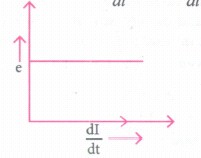
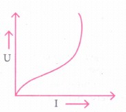
The current flowing through an inductor of self-inductance L is continuously increasing plot a graph showing the variation of
a) Magnetic flux versus current.
b) induced emf versus \(\frac{dI}{dt}\)
c) magnetic potential energy stored versus the current.
17.
Deduce the expression for the torque \(\vec { \tau } \) when \(\hat { n } \) unit vector n is at an angle 8 with the field.
18.
A wire of length 0.3m moves with a speed of 20 m/s perpendiculars to the magnetic field of induction Iwb/m2. Calculate the induced emf.
19.
A long solenoid with 20 turns per cm has a small loop of area 2cm2 placed inside the solenoid normal to its axis. If the circuit carried by the solenorid changes steadily from lA to 3A in 0.2s. What is the-induced emf in the loop while the current is changing.
20.
Drive an expression of Potential energy of a bar magnet in a uniform magnetic field.
21.
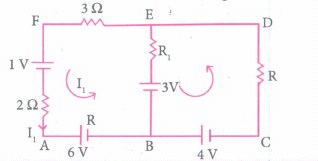
Use Kirchhoff's laws (rules) to determine the potential difference between points A and D when no current flows in the arm BE of the electric network shown in the figure below.
22.
An aluminium wire of diameter 0.24 cm is connected in series to a copper wire of diameter 0.16 cm. The wires carry an electric current of 10 A. Determine the current density in aluminium wire.
23.
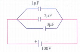
In the circuit shown in figure. Find
(i) The equivalent capacitance and
(ii) The charge stored in each capacitor
24.
Two metallic wires P1 & P2 of the same material & same length but different cross sectional areas A1 & A2 are joined together & connected to a source of emf. Find the ratio of the drift velocities of free electrons in the two wires when they are connected
(i) in series &
(ii) in parallel.
25.
Derive a relation between mean or average value of AC and its peak value.
26.
Explain the variation of resistivity of conductor and semiconductor with change in temperature.
27.
How many electrons are there in one coulomb of negative charge?
28.
Explain in detail the Electrostatic Potential difference between the charges.
1.
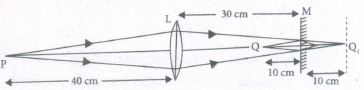
We first consider the effect of the lens. For the
lens, we have
u = - 40 cm and f = + 20 cm
Using the lens formula, we get
\(\cfrac { 1 }{ { v }_{ 1 } } -\cfrac { 1 }{ \left( -40 \right) } =\cfrac { 1 }{ 20 } \) ஃv1 = + 40 cm
Had there been the lens only the image would have been formed at Q1. The plane mirror M is at a distance of 30 cm from lens 1. We can, therefore, think of Q1, as a virtual object, located at a distance of 10cm, behind the plane mirror M. The plane mirror, therefore, forms a real image (of this virtual object Q1) at Q, 10 cm in front of it.
2.
The focal length of the lens (refractive index μ1) in a liquid of refractive index μ2 is
Formula:
\({ f }_{ 1 }=\cfrac { { \mu }_{ 1 }-1 }{ \frac { { \mu }_{ 1 } }{ { \mu }_{ 2 } } } \times { f }_{ a }\)
Given :
\({ \mu }_{ 2 }>{ \mu }_{ 1 },i.e,\cfrac { { \mu }_{ 1 } }{ { \mu }_{ 2 } } <1\)
So,\({ \quad f }_{ 1 }=\cfrac { { \mu }_{ 1 }-1 }{ 1-\frac { { \mu }_{ 1 } }{ { \mu }_{ 2 } } } { f }_{ a }\)
So the focal length of the lens in the liquid will be of the opposite sign of the focal length of the lens in air, i.e., the nature of the lens will change. Hence, the lens would now behave like a diverging (concave) lens.
3.
Here, m = -20, me = 5, ve = -20 cm
For eyepiece, \({ m }_{ e }=\cfrac { { v }_{ e } }{ { u }_{ e } } \)
\(\Rightarrow 5=\cfrac { -20 }{ 5 } \Rightarrow { u }_{ e }=\cfrac { -20 }{ 5 } =-20cm\)
Using lens formula,
\(\cfrac { 1 }{ { v }_{ e } } -\cfrac { 1 }{ { u }_{ e } } =\cfrac { 1 }{ { f }_{ e } } =-\cfrac { 1 }{ 20 } +\cfrac { 1 }{ 4 } =\cfrac { 1 }{ { f }_{ e } } \)
\(\Rightarrow \cfrac { -1+5 }{ 20 } =\cfrac { 1 }{ { f }_{ e } } \Rightarrow { f }_{ e }=5cm\)
Now, total magnification
m = me x mo
-20 = 5 x mo ⇒ mo = -4
Also \(\left| { v }_{ o } \right| +\left| { u }_{ e } \right| =14\)
\(\left| { v }_{ e } \right| +\left| -4 \right| =14\)
vo = 14 - 4 = 10 cm
\({ m }_{ o }=1-\cfrac { { n }_{ o } }{ { f }_{ o } } \Rightarrow -4=1-\cfrac { 10 }{ { f }_{ e } } \)
4.
(a) The number of photons incident normally per unit area per unit time in determined the intensity of radiations.
(b) (i) Red light, because the energy of red light is less than that of blue light (hv)R < (hv)B
(ii) Blue light, because the energy of blue light is greater than the of red light (hv)B > (hv)R.
5.
As, λ = \(\frac { h }{ \sqrt { 2mqV } } \) or
\(\lambda =\left( \frac { h }{ \sqrt { 2q } } .\frac { 1 }{ \sqrt { m } } \right) \frac { 1 }{ \sqrt { v } } \)
or \(\frac { \lambda }{ \frac { 1 }{ \sqrt { v } } } =\frac { h }{ \sqrt { 2q } } .\frac { 1 }{ \sqrt { m } } \)
As the charge on the two particles is the same, we get
Slope ∝ \(\frac { 1 }{ \sqrt { m } } \)
Hence, particle with lower mass (m2) will have greater slope.
6.
de Broglie wavelength λ = \(\frac { h }{ \sqrt { 2m{ E }_{ K } } } \)
Here Ek =150 eV = 150 x 1.6 x 10-19 J
=2.4 x 10⁻¹⁷ J
∴ λ = \(\frac { 6.63\times { 10 }^{ -34 } }{ \sqrt { \left[ 2\times 1.67\times { 10 }^{ -27 }\times 2.4\times 10^{ -17 } \right] } } \) m
= 0.02335 Å
7.
Principle: Diffraction effects are observed for beams of electrons scattered by the crystals.
λ = \(\frac { h }{ p } =\frac { h }{ \sqrt { 2mE_{ k } } } =\frac { h }{ \sqrt { 2meV } } \)
= \(\frac { 6.63\times { 10 }^{ -34 } }{ \sqrt { 2\times 9.1\times 10^{ -31 }\times 1.6\times 10^{ -19 }\times 120 } } \)
λ = 0.112 nm.
8.
(i) Radar basically stands for Radio Detection and Ranging System.
(ii) It is one of the important applications of communication systems' and is mainly used to sense, detect, and locate distant objects like aircraft, ships, spacecraft, etc.
(iii) The angle, range, or velocity of the objects that are invisible to the human eye can be determined.
(iii) Radar uses electromagnetic waves for communication. The electromagnetic signal is initially radiated into space by an antenna in all directions.
(iv) When this signal strikes the targeted object, it gets reflected or reradiated in many directions.
(v) This reflected (echo) signal is received by the radar antenna which in turn is delivered to the receiver.
(vi) Then, it is processed and amplified to determine the geographical statistics of the object. The range is determined by calculating the time taken by the signal to travel from RADAR to the target and back.
Applications :
Radars find extensive applications in almost all fields.
(i) In military, it is used for locating and detecting the targets.
(ii) It is used in navigation systems such as ship borne surface search, air search and weapons guidance systems.
(iii) To measure precipitation .rate and wind speed in meteorological observations, Radars are used.
(iv) It is employed to locate and rescue people in emergency situations.
9.
Advantages of robotics:
(i) The robots are much cheaper than humans.
(ii) Robots never get tired like humans. It can work for 24 x 7. Hence absenteeism in work place can be reduced.
(iii) Robots are more precise and error free in performing the task.
(iv) Stronger and faster than humans.
(v) Robots can work in extreme environmental conditions: extreme hot or cold, space or underwater. In dangerous situations like bomb detection and bomb deactivation.
(vi) In warfare, robots can save human lives.
(vii) Robots are significantly used in handling materials in chemical industries especially in nuclear plants which can lead to health hazards in humans.
Disadvantages of Robotics:
(i) Robots have no sense of emotions or conscience.
(ii) They lack empathy and hence create an emotionless workplace.
(iii) If ultimately robots would do all the work, and the humans will just sit and monitor them, health hazards will increase rapidly.
(iv) Unemployment problem will increase.
(v) Robots can perform defined tasks and cannot handle unexpected situations.
(vi) The robots are well programmed to do a job and if a small thing goes wrong it ends up in a big loss to the company.
(vii) If a robot malfunctions, it takes time to identify the problem, rectify it, and even reprogram if necessary. This process requires signi cant time.
(viii) Humans cannot be replaced by robots in decision making.
(ix) Till the robot reaches the level of human intelligence, the humans in work place will exit.
10.
Insulators:
(i) The valence band and the conduction band are separated by a large energy gap.
(ii) The forbidden energy gap is approximately 6 eV in insulators.
(iii) The gap is very large that electrons from valence band cannot move into conduction band even on the application of strong external electric field or the increase in temperature.
Metals
(i) In metals, the valence band and conduction band overlap.
(ii) Hence, electrons can move freely into the conduction band which results in a large number of free electrons in the conduction band.
Semiconductors
(i) In semiconductors, there exists a narrow forbidden energy gap (E < 3eV) between - g the valence band and the conduction band.
(ii) Free electrons are small in number, the conductivity of the semiconductors is not as high as that of the conductors.
11.
\(\frac { R }{ { R }_{ 0 } } ={ \left( \frac { 1 }{ 2 } \right) }^{ n }\)
\(\frac { 3.125 }{ 100 } ={ \left( \frac { 1 }{ 2 } \right) }^{ n }\)
\(\frac { 1 }{ 32 } ={ \left( \frac { 1 }{ 2 } \right) }^{ n }={ \left( \frac { 1 }{ 2 } \right) }^{ 5 }\)
\(n=5,\frac { t }{ T } =5\)
t = 5T
12.
Strength of radioactive source
= 8.0 mCi = 8.0 x 10⁻³ Ci
= 8.0 x 10-3 x 3.7 x 1010 disintegrations s-1
Since the strength of the source decreases with time,
\(\therefore \frac { dN }{ dt } =-29.6\times { 10 }^{ 7 }\)
But \(\frac { dN }{ dt } =-\lambda N\)
\(\therefore =-\lambda N=-29.6\times { 10 }^{ 7 }\)
or \(\lambda N=-29.6\times { 10 }^{ 7 }N=\frac { 29.6\times { 10 }^{ 7 } }{ \lambda } \)
or \(N=\frac { 29.6\times { 10 }^{ 7 }\times T }{ 0.693 } \)
13.
Formula:
Intensity, I = \(\frac{Power\ of\ visible\ light}{Area}\)
\(I=\frac { \frac { 5 }{ 100 } \times 100 }{ 4\pi { (1) }^{ 2 } } =0.4{ W/m }^{ 2 }\)
14.
(i) \(\lambda =\frac { 2\pi }{ 300\pi } =\frac { 1 }{ 150 } m\)
\([{ B }_{ y }={ B }_{ o }sin2\pi \left( \frac { x }{ \lambda } +\frac { t }{ r } \right) ]\)
(ii) \(\\ { E }_{ o }=c,{ B }_{ o }=3\times { 10 }^{ 8 }\times 8\times { 10 }^{ -6 }=2400{ Vm }^{ -1 }\)
15.
Total number of turns, N = 500
Length of solenoid, l = 0.5m
Current, I = 5A
Radius, r = 1 cm = 1 x 10⁻²m
B = μ0nI = \(\frac { { \mu }_{ 0 }NI }{ l } \)
B = \(\frac { 4\pi \times { 10 }^{ -7 }\times 500\times 5 }{ 0.5 } \)
B = 6.28 x 10⁻³T
Here, \(\frac { l }{ r } =\frac { 0.5 }{ 10^{ -2 } } \) = 50
∵ l >> r (an ideal solenoid)
16.
(a) Given: Magnetic flux versus current:

(b) Induced emf versub \(\frac{dI}{dt}e=-L\frac{dI}{dt}\)
(c) Magnetic potential energy versus current:
U = \(\frac12{LI}^2\)
U α I2
17.
In the general case, the unit normal vector \(\hat { n } \) and magnetic field \(\vec { B } \) is with an angle 8 as shown in Figure.
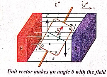
(a) The force on section PQ
\(\vec { i } =a\hat { j } \) and \(\vec { B } =B\hat { i } \)
\(\vec { { F }_{ PQ } } =\vec { Il } \times \vec { B } =IaB(\hat { j } \times \hat { j } )=-IaB\hat { k } \)
Since the unit vector normal to the plane \(\hat { n } \) is along the direction of .\(\vec { k } \)
(b) The force on section QR
\(\vec { l } =bcos\left( \frac { \pi }{ 2 } -\theta \right) \hat { i } -sin\left( \frac { \pi }{ 2 } -\theta \right) \hat { k } \)
\(\vec { { F }_{ QR } } =\vec { Il } \times \vec { B } =-IbB\left( \frac { \pi }{ 2 } -\theta \right) \hat { j } \)
\(\vec { { F }_{ QR } } =-IbBcos\theta \hat { j } \)
(c) The force on section RS
\(\vec { l } =a\hat { j } \) and \(\vec { B } =B\hat { i } \)
\(\vec { { F }_{ RS } } =\vec { Il\times \vec { B } } =IaB(\hat { j } \times \hat { j } )=-IaB\hat { k } \)
Since the unit vector normal to the plane is along the direction of \(\hat { k } \).
(d) The force on section SP
\(\vec { l } =bcos\left( \frac { \pi }{ 2 } -\theta \right) \hat { i } +sin\left( \frac { \pi }{ 2 } +\theta \right) \hat { k } \quad \vec { B } =B\hat { i } \)
\(\vec { { F }_{ SP } } =\vec { Il } \times \vec { B } =IbBsin\left( \frac { \pi }{ 2 } -\theta \right) \hat { j } \)
\(\vec { { F }_{ SP } } =-IbBcos\theta \hat { j } \)
The net force on the rectangular loop is
\(\vec { { F }_{ net } } =\vec { { F }_{ PQ } } +\vec { { F }_{ QR } } +\vec { { F }_{ RS } } +\vec { { F }_{ SP } } \)
\({ F }_{ net }=IaB\hat { k } -IbBcos\theta \hat { j } -IaB\hat { k } +IbBcos\theta \hat { j } \)
\(\vec { { F }_{ net } } =\vec { 0 } \)
Hence, the net force on the rectangular loop in this configuration is also zero. Notice that the force on section QR and SP is not zero here. But, they have equal and opposite effects, but we assume that the loop to be rigid, so no deformation. So, no torque was produced by these two sections.
Even though the forces PQ and RS also are equal and opposite, they are not collinear. So these two forces constitute a couple as shown in Figure (a). Hence the net torque produced by these two forces about the axis of the rectangular loop is given by
\(\vec { { \tau }_{ net } } =baBIsin\theta \hat { k } =ABIsin\theta \hat { k } \)
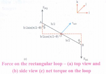
\(\vec { OA } =\frac { b }{ 2 } cos\left( \frac { \pi }{ 2 } -\theta \right) (-\hat { i } )+\frac { b }{ 2 } cos\left( \frac { \pi }{ 2 } -\theta \right) (-\hat { k } )\)
=\(\frac { b }{ 2 } (-sin\theta \hat { i } +cos\theta \hat { k } )\)
\(\vec { OB } =\frac { b }{ 2 } cos\left( \frac { \pi }{ 2 } -\theta \right) (\hat { i } )+\frac { b }{ 2 } cos\left( \frac { \pi }{ 2 } -\theta \right) (\hat { k } )\)
=\(\frac { b }{ 2 } (-sin\theta \hat { i } +cos\theta \hat { k } )\)
\(\vec { OA } \times \vec { { F }_{ PQ } } =\left\{ \frac { b }{ 2 } (-sin\theta \hat { i } +cos\theta \hat { k } \right\} \times \left\{ IaB\hat { k } \right\} \)
= \(\frac { 1 }{ 2 } IabBsin\theta \hat { j } \)
\(\vec { OA } \times \vec { { F }_{ RS } } =\left\{ \frac { b }{ 2 } (sin\theta \hat { i } +cos\theta \hat { k } \right\} \times \left\{ -IaB\hat { k } \right\} \)
= \(\frac { 1 }{ 2 } IabBsin\theta \hat { j } \)
The net torque \(\vec { \tau _{ net } } =IaBsin\theta \hat { j } \) ..........(1)
Note that the net torque is in the positive y-direction which tends to rotate the loop in a clockwise direction about the y axis. If the current is passed in the other way (P⟶S⟶R⟶Q⟶P), then total torque will point in the negative y-direction which tends to rotate the loop in an anticlockwise direction about the y-axis.
Another important point is to note that the torque is less in this case compared to the earlier case (where the \(\hat { n } \) is perpendicular to the magnetic field \(\vec { B } \)). It is because the perpendicular distance is reduced between the forces \(\vec { { F }_{ PQ } } \) and \(\vec { { F }_{ RS } } \) in this case.
The equation (1) can also be rewritten in terms of magnetic dipole moment \(\vec { { p }_{ m } } =I\vec { A } =Iab\hat { n } \)
\(\vec { \tau _{ net } } =\vec { p } \times \vec { B } \).
18.
Given:
Velocity, v = 20 m/s
Length, 1 = 0.3m
Angle, θ = 90°
Magnetic field, B = 1 Wb/m?
Formula:
Induced emf, e = Blv
e = 1 x 0.3 x 20 = 6V
19.
Give: No. of turns of long solenoid = 20 = N
No. of turns of small loop N2= 1
Length l = 1 = 1 crn = 10-2m2
To find:
Induced emf e = ?
\(e=\mu \frac { dI }{ dt } \)
Formula:
Mahal inductance of a solenoid
\(\mu =\frac { { \mu }_{ o }{ N }_{ 1 }{ N }_{ 2 }{ A }_{ 2 } }{ l } \)
Solution:
\(\mu =\frac { 4\pi \times { 10 }^{ -7 }\times 20\times { 10 }^{ -4 }\times 2\times 1 }{ { 10 }^{ -2 } } \)
=160π x 10-9 x \(\frac { (3-1) }{ 0.2 } \)
= 160π x 10-8
= 502 x 10-8 = 5.02 x 10⁻⁶ V
20.
When a bar magnet (magnetic dipole) of dipole moment \(\vec { { p }_{ m } } \) is held at an angle θ with the direction of a uniform magnetic field \(\vec { { B } } \), as shown in Figure the magnitude of the torque acting on the dipole is
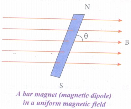
\(|\vec { \tau _{ B } } |=|\vec { { p }_{ m } } ||\vec { B } |sin\theta \)
If the dipole is rotated through a very small angular displacement dθ against the torque ፒB at constant angular velocity, then the work done by external torque \((\vec { { \tau }_{ ext } } )\) for this small angular displacement is given by
dW = \(|\vec { { { \tau }_{ ext } } } |\) dθ
Since the bar magnet to be moved at constant angular velocity, it implies \(|\vec { { \tau }_{ B } } |=|\vec { \tau _{ ext } } |\)
dW = PmB sinθ dθ
Total work done in rotating the dipole from θ' to θ is
W =\(\int _{ \theta ' }^{ \theta }{ \tau d\theta } =\int _{ \theta ' }^{ \theta }{ p_{ m } } Bsin\theta d\theta ={ p }_{ m }B[-cos\theta d\theta ]_{ \theta ' }^{ \theta }\)
W = pmB(cosθ - cosθ')
This work done is stored as potential energy in bar magnet at an angle θ when it is rotated from θ' to θ and it can be written as
U = pmB(cosθ - cosθ') .........(1)
In fact, equation (1) gives the difference in potential energy between the angular positions θ' and θ. We can choose the reference point θ' = 90°, so that second term in the equation becomes zero and the equation (1) can be written as
U = -pmB(cosθ) ............(2)
The potential energy stored in a bar magnet in a uniform magnetic field is given by
U = -\(\vec { { p }_{ m } } .\vec { B } \) ............(3)
Case 1
(i) If θ = 0°, then
U = PmB (cos00) = - PmB
(ii) If θ = 180°, then
U = PmB (cos 180°) = pmB
We can infer from the above two results, the potential energy of the bar magnet is minimum when it is aligned along the external magnetic field and maximum when the bar magnet is aligned anti-parallel to an external magnetic field.
21.
Applying kirchhoff's law (loop rule) for loop ABEFA, (since current is reversed, negative sing on both sides)
= R1 x 0 - 3 x I1 - 2I1 = -6-3-1
= 3I1 - 2I1= -10
= 5I1 = -10
I1 = 2A
for loop BCDEB
= R x I1 - R1 x 0 = -4 + 3
= I1R = 1
\(R=\cfrac { 1 }{ 2 } \Omega \)
Potential difference between A and D through path ABCD is
= 6-4 + VAD = I1R
= 10 + VAD = -2 x \(\cfrac { 1 }{ 2 } \)
= 10 + CAD = -1
VAD = -9 Volt
22.
Diameter d 0.24 cm = 0.24 x 10⁻² m
radius \(r=\cfrac { d }{ 2 } =0.12\times { 1 }^{ -2 }m\)
Current, I = 10A
Current density \(J=\cfrac { 1 }{ A } =\cfrac { 1 }{ { \pi r }^{ 2 } } \)
= \(\cfrac { 10 }{ 3.14\times \left( 0.12\times { 10 }^{ -2 } \right) ^{ 2 } } \)
= 2.2 x 10⁶ Am-2
23.
(i) The equivalent capacitance is,
Cp = C1+ C2 + C3
= (1 + 2 + 3) = 6μF
(ii) Total charge, q = CμV
= 6 x 10-6 x 100 = 600μC
q1 = C1V = 1 x 100 = 100μC
q2 = C2V = 2 x 100 = 200μC
q3 = C3V = 3 x 100 = 300μC
24.
(i) In series the circuit remains the same
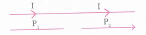
\(\therefore I=neA_{ 1 }{ V }_{ d_{ 1 } }=n{ A }_{ 2 }{ ev }_{ { d }_{ 2 } }\)or \(\cfrac { { vd }_{ 1 } }{ { vd }_{ 2 } } =\cfrac { { A }_{ 2 } }{ { A }_{ 1 } } \)
(ii) In parallel the potential difference is the same but the circuits are different
\(V={ I }_{ 1 }{ R }_{ 1 }=n{ A }_{ 1 }{ ev }_{ d_{ 1 } }\times \cfrac { \rho l }{ { A }_{ 1 } } ={ n }_{ 1 }e\rho v_{ d_{ 1 } }l\)
\(V={ I }_{ 2 }{ R }_{ 2 }={ n }_{ 1 }e\rho { v }_{ { d }_{ 1 } }l\) \(\left[ \because { R }_{ 1 }=\cfrac { \rho l }{ { A }_{ 1 } } \right] \)
Now I1R1 = I2R2 \(\therefore \cfrac { { V }_{ d_{ 1 } } }{ { V }_{ d_{ 2 } } } =1\)
25.
(i) The magnitude of an alternating current in a circuit changes from one instant to other instant and its direction also reverses for every half cycle.
(ii) During positive half cycle, current is taken as positive and during negative cycle it is negative. Therefore mean or average value of symmetrical alternating current over one complete cycle is zero.
(iii) Therefore the average or mean value is measured over one half of a cycle. These electrical terms, average current and average voltage can be used in both AC and DC circuit analysis and calculations.
(iv) The average value of alternating current is defined as the average of all values of current over a positive half-cycle or negative half-cycle.
(v) The instantaneous value of sinusoidal alternating current is given by the equation
i = Im sin ωt or i = Im sinθ (where θ = ωt) whose graphical representation is given in Figure.
(vi) The sum of all currents over a half-cycle is given by area of positive half-cycle (or negative half-cycle). Therefore,
Iav = \(\frac{Area \ of \ positive \ half-cycle (or \ negative \ half -cycle)}{Base \ lenght \ of \ half - cycle)}\) ...(1)
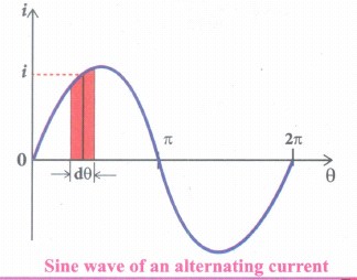
(vii) Consider an elementary strip of thickness dθ in the positive half-cycle of the current wave. Let i be the mid-ordinate of that strip.
Area of the elementary strip = i dθ
Area of positive half-cycle
= \(\int _{ 0 }^{ \pi }{ id\theta } =\int _{ 0 }^{ \pi }{ { I }_{ m }sin\theta d\theta } \)
= \({ I }_{ m }{ [-cos\theta ] }_{ 0 }^{ \pi }={ -I }_{ m }[cos\pi -cos0]=2{ I }_{ m }\)
Substituting this in equation (1), we get (The base length of half-cycle is π)
Average value of AC, Iav = \(\frac { { 2I }_{ m } }{ \pi } \)
Iav = 0.637 Im
(viii) Hence the average value of AC is 0.637 times the maximum value Im of the alternating current. For negative half cycle, Iav = -0.637 Im
26.
(i) The resistivity of a material is dependent on temperature. The resistivity of a conductor increases with increase in temperature according to the expression
\({ \rho }_{ r }={ \rho }_{ 0 }[I+\alpha (T-{ T }_{ 0 })\)
(ii) Where PT is the resistivity of a conductor at ToC, is the resistivity of the conductor at some reference temperature To (usually at 20°C), and a is the temperature coefficient of resistivity.
(iii) It is defined as the ratio of increase in resistivity per degree rise in temperature to its resistivity at To
From equation (1), we can write
\({ \rho }_{ r }-{ \rho }_{ 0 }=\alpha { \rho }_{ 0 }(T-{ T }_{ 0 })\)
\(\therefore \alpha =\cfrac { { \rho }_{ r }-{ \rho }_{ 0 } }{ { \rho }_{ 0 }(T-{ T }_{ 0 }) } =\cfrac { \Delta \rho }{ { \rho }_{ 0 }\Delta T } \)
where \(\Delta \rho ={ \rho }_{ r }-{ \rho }_{ 0 }\) is change in resistivity for a change in temperature \(\Delta T=T-{ T }_{ 0 }\) Its unit is per oC \(\alpha \) of conductor:
(iv) For conductors a is positive. If the temperature of a conductor increases, the average kinetic energy of electrons in the conductor increases. This results in more frequent collisions and hence the resistivity increases.
(v) The graph of the Even though, the resistivity of conductors like metals varies linearly for wide range of temperatures, there also exists a nonlinear region at very low temperatures.
(vi) The resistivity approaches some finite values the temperature approaches absolute zero
(vii) As the resistance is directly proportional to the resistivity of the material, we can also write the resistance of a conductor at temperature T °C as
\({ R }_{ T }={ R }_{ 0 }\left[ 1+\left( T-{ T }_{ 0 } \right) \right] \)
\(\alpha =\cfrac { { R }_{ T }-{ R }_{ 0 } }{ { R }_{ 0 }\left( T-{ T }_{ 0 } \right) } =\cfrac { I }{ { R }_{ 0 } } \cfrac { \Delta R }{ \Delta T } \)
\(\alpha =\cfrac { I }{ { R }_{ 0 } } \cfrac { \Delta R }{ \Delta T } \)
where \(\Delta R={ R }_{ r }-{ R }_{ 0 }\) is the change in resistance during the change in temperature \(\Delta T=T-{ T }_{ 0 }\)
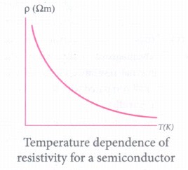
(viii) An of semiconductors For semiconductors, the resistivity decreases with increase in temperature. As the temperature increases, more electrons will be liberated from their atoms. Hence the current increases and therefore the resistivity decreases. A semiconductor with a negative temperature coefficient of resistance is called a thermistor.
27.
Charge of an electron, e = 1.6 x 10⁻¹⁹C
q = 1C
∴ No of electrons, n = \(\frac{q}{e}\)
\(n=\frac { 1 }{ 1.6\times { 10 }^{ -19 } } \)
= 6.25 x 10¹⁸
n = 6.25 x 10¹⁸ electrons
28.
(i) Consider a positive charge q kept fixed at the origin which produces an electric field \(\overset { \rightarrow }{ E } \) around it.
(ii) A positive test charge q' is brought from point R to point P against the repulsive force between q and q' as shown in Figure. Work must be done to overcome this repulsion. This work done is stored as potential energy.
(iii) The test charge q' is brought from R to P with constant velocity which means that external force used to bring the test charge q' from R to P must be equal and opposite to the coulomb force \(\left( { \overset { \rightarrow }{ E } }_{ ext }=-{ \overset { \rightarrow }{ F } }_{ coloumb } \right) \)
The work done is
\(W=\int _{ R }^{ P }{ { \overset { \rightarrow }{ F } }_{ ext } } .d\overset { \rightarrow }{ r } \quad \quad \quad ...(1)\)
(iii) Since coulomb force is conservative, work done is independent of the path and it depends only on the initial and final positions of the test charge. If potential energy associated with q' at P is Up and that at R is UR' then difference in potential energy is defined as the work done to bring a test charge q' from point P to R and is given as Up - U R = W.
\(\Delta U=\int _{ R }^{ P }{ { \overset { \rightarrow }{ F } }_{ ext } } .d\overset { \rightarrow }{ r } \)
\(Since{ \overset { \rightarrow }{ F } }_{ ext }=-{ \overset { \rightarrow }{ F } }_{ coloumb }=-q'\overset { \rightarrow }{ E } \)
\(\Delta U=\int _{ R }^{ P }{ \left( -q'\overset { \rightarrow }{ E } \right) } .d\overset { \rightarrow }{ r } =q'\int _{ R }^{ P }{ \left( -\overset { \rightarrow }{ E } \right) } .d\overset { \rightarrow }{ r } \)

12th Standard Syllabus & Materials
12th Standard
TN 12th Computer Applications களப்பெயர் முறைமை (DNS) Sample Question Papers Study Material - QB365 Set A
NEW12th Standard
TN 12th Computer Applications வலையமைப்பு எடுத்துக்காட்டுகள் மற்றும் நெறிமுறைகள் Sample Question Papers Study Material - QB365 Set A
NEW12th Standard
TN 12th Computer Applications கணினி வலையமைப்பு ஓர் அறிமுகம் Sample Question Papers Study Material - QB365 Set A
NEW12th Standard
TN 12th Computer Applications PHP-உடன் MySQL-ஐ இணைத்தல் Sample Question Papers Study Material - QB365 Set A



Tamilnadu Stateboard 12th Standard Subjects

Maths

Chemistry
Physics

Biology

Computer Science

Business Maths and Statistics

Economics

Commerce

Accountancy

History

Computer Applications
Biology
Computer Technology
Computer Applications
Computer Science
Business Maths and Statistics
Commerce
Economics
Maths
Chemistry
Physics
Computer Technology
History
Accountancy

Tamil

English

French
Tamilnadu Stateboard Standards

