
 100% FREE ACCESS
12th Standard Syllabus & Materials
12th Standard
TN 12th Computer Applications மின்னணு தரவு பரிமாற்றம் Sample Question Papers Study Material - QB365 Set A
NEW12th Standard
TN 12th Computer Applications மின் - வணிக பாதுகாப்பு அமைப்புகள் Sample Question Papers Study Material - QB365 Set A
NEW12th Standard
TN 12th Computer Applications மின்னணு செலுத்தல் முறைகள் Sample Question Papers Study Material - QB365 Set A
NEW12th Standard
TN 12th Computer Applications மின் - வணிகம் Sample Question Papers Study Material - QB365 Set A
NEW12th Standard
TN 12th Computer Applications திறந்த மூல கருத்துருக்கள் Sample Question Papers Study Material - QB365 Set A
NEW12th Standard
TN 12th Computer Applications வலையமைப்பு வடமிடல் Sample Question Papers Study Material - QB365 Set A

Published on: 02/09/2022
QB365 provides a detailed and simple solution for every Possible Book Back Questions in Class 12 Physics Subject - Retirement and Death of a Partner, English Medium. It will help Students to get more practice questions, Students can Practice these question papers in addition to score best marks.
Download Tamil Nadu 12th Standard Physics question papers, model tests, one-mark questions, important questions, and public exam papers in PDF format. Free study materials and answer keys for TN State Board students.
Questions + Answers key
Take MCQ Physics Test1.
Obtain the equation for resolving power of microscope.
2.
Discuss diffraction at single slit and obtain the condition for nth minimum.
3.
Prove the laws of reflection using Huygen's principle.
4.
Mention different parts of spectrometer and explain the preliminary adjustments.
5.
Explain the experimental determination of refractive index of the material of the prism using spectrometer.
6.
Discuss about the simple microscope and obtain the equations for magnification for near point focusing and normal focusing.
7.
Obtain the equation for resolving power of optical instruments.
8.
Discuss the experiment to determine the wavelength of different colours using diffraction grating.
9.
Discuss the experiment to determine the wavelength of monochromatic light using diffraction grating.
10.
Discuss the diffraction at a grating and obtain the condition for the mth maximum.
11.
Discuss the interference in thin films and obtain the equations for constructive and destructive interference for transmitted and reflected light.
12.
Explain the Young’s double slit experimental setup and obtain the equation for path difference.
13.
Obtain the equation for resultant intensity due to interference of light.
14.
Prove law of refraction using Huygens’ principle.
15.
Prove law of reflection using Huygens’ principle.
16.
Discuss about astronomical telescope.
17.
Explain about compound microscope and obtain the equation for the magnification.
1.
(i) A microscope is used to see the details of the object under observation.
(ii) Good microscope should not only magnify the object but also resolve the two points on an object which are separated by the smallest distance dmin. Actually, dmin is the resolution and its reciprocal is the resolving power.
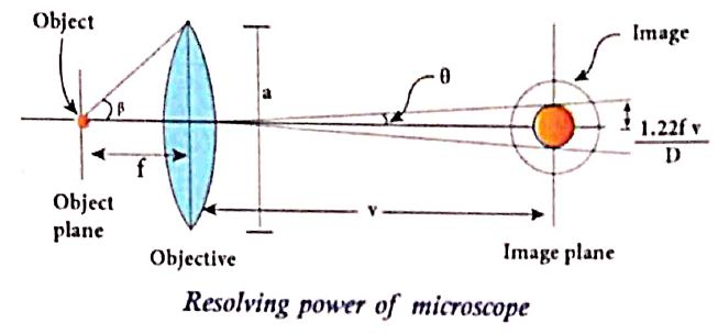
Resolving power of a microscope
The spatial resolution (radius of central maxima) is
\(r_{0}=\frac{1.22 \lambda f}{a}\) .......(1)
where 'a' is width of the aperture/slit.
In microscope, the object distance is just more than the focal length f and the image is formed at v as shown in the Figure. Hence, f in equation is replaced by v.
\(r_{0}=\frac{1.22 \lambda v}{a}\) ......(2)
In the place of focal length f we have the image distance v. If the difference between the two points on the object to be resolved is dmin. Then the magnification m is,
\(m=\frac{r_{0}}{d_{\min }}\) ........(3)
\(\mathrm{d}_{\min }=\frac{\mathrm{r}_{0}}{\mathrm{~m}}=\frac{1.22 \lambda \mathrm{v}}{\mathrm{am}}=\frac{1.22 \lambda \mathrm{v}}{\mathrm{a}(\mathrm{v} / \mathrm{u})}=\frac{1.22 \lambda \mathrm{u}}{\mathrm{a}}\) [∴ m = v/u]
\(\mathrm{d}_{\min }=\frac{1.22 f\lambda}{\mathrm{a}}[\therefore \mathrm{u} \approx \mathrm{f}]\) ..............(4)
On the other side,
\(2 \tan \beta \approx 2 \sin \beta=\frac{a}{f} \therefore[a=f 2 \sin \beta]\) .........(5)
\(\mathrm{d}_{\min }=\frac{1.22 \lambda}{2 \sin \beta}\) .................(6)
To further reduce the value of dmin the optical path of the light is increased by immersing the objective of the microscope into a bath containing oil of refractive index n.
\(\mathrm{d}_{\min }=\frac{1.22 \lambda}{2 \mathrm{n} \sin \beta}\) ...............(7)
Such an objective is called the oil-immersed objective. The term n sin β is called numerical aperture NA.
\(\mathrm{d}_{\min }=\frac{1.22 \lambda}{2(\mathrm{NA})}\) ...................(8)
The resolvins power RM of microscope is
\(\mathrm{R}_{M }=\frac{1}{d_{min}}\frac{2(NA)}{1.22\lambda}\)
2.
(i) Let a parallel beam of light (plane wavefront) fall normally on a single slit AB of width a as shown in figure. The diffracted beam falls on a screen kept at a distance D from the slit. The center of the slit is C.
(ii) A straight line through C perpendicular to the plane of slit meets the center of the screen at O. Consider any point P on the screen. All the light reaching the point P from different points on the slit make an angle \(\theta\) with the normal CO.
(iii) All the light waves coming from different points on the slit interfere at point P (and other points) on the screen to give the resultant intensities. The point P is in the geometrically shadowed region, up to which the central maximum is spread due to diffraction as shown Figure.
(iv) We need to give the condition for the point P to be of various minima.
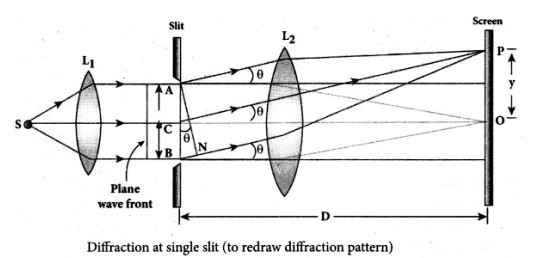
(v) The basic idea is to divide the slit into much smaller even number of parts. Then, add their contributions at P with the proper path difference to show that destructive interference takes place at that point to make it minimum. To explain maximum, the slit is divided into odd number of parts.
Condition for P to the nth order minimum:
(i) Dividing the slit into 2n number of (even number of) equal parts makes the light produced by one of the corresponding points to be cancelled by its counterpart. Thus, the condition for nth order minimum is, \(\frac{a}{2 n} \sin \theta=\frac{\lambda}{2}\)
\(a \sin \theta=n \lambda\) (nth minimum)
Where, n = 1,2,3... is the order of diffraction minimum.
3.
(i) Consider a parallel beam of light, incident on a reflecting plane surface such as a plane mirror XY as shown in Figure.
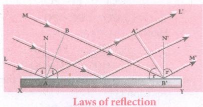
(ii) The incident wavefront is AB and the reflected wavefront is A'B' in the same medium. These wavefronts are perpendicular to the incident rays L, M and reflected rays L', M' respectively.
(iii) By the time point A of the incident wavefront touches the reflecting surface, point B is yet to travel a distance BB' to touch the reflecting surface a B'.
(iv) When point B falls on the reflecting surface at H', point A would have reached A.
(v) This is applicable to all the points on the wavefront. Thus, the reflected wavefront A'B' emanates as a plane wavefront. The two normals Nand N' are considered at the points where the rays Land Mfallon the reflecting surface.
(vi) As reflection happens in the same medium, the speed of light is the same before and after the reflection.
(vii) Hence, the time is taken for the ray to travel from B to B' is the same as the time taken for the ray to travel from A to A'.
(viii) Thus, the distance BB' is equal to the distance AA'; (A~A' = BB').
(a) The incident rays, the reflected rays, and the normal are in the same plane.
(b) Angle of incidence,\(\angle i=\angle NAL={ 90 }^{ o }-\angle NAB=\angle BAB'\)
Angle of reflection,
∠r= ∠N' B' M' = 900 - ∠N' B' A' = A' B' A'
(ix) For the two right-angle triangles, ΔABB' and ΔB' A' A', the right angles, ∠B and ∠A' are equal, (∠B and∠A = 900); the two sides, ∠A' and ∠B' are equal, (AA'= BB'); the side AB' is common.
(x) Thus, the two triangles are congruent. As per the property of congruency, the two angles, ∠BAB' and A' B' A' must also be equal.
i = r
Hence, the laws of reflection are proved.
4.
i) The spectrometer is an optical instrument used to analyse the spectra of different sources of light, to measure the wavelength of different colours and to measure the refractive indices of materials of prisms.
ii) It basically consists of three parts namely. They are (i) collimator, (ii) prism table and (iii) Telescope
Adjustments of the spectrometer
(i) The following adjustments must be done in a spectrometer before doing the experiment.
(a) Adjustment of the eyepiece:
The telescope is turned towards an illuminated surface and the eyepiece is moved to and fro until the cross wires are clearly seen.
(b) Adjustment of the telescope:
The telescope is adjusted to' receive parallel rays by turning it towards a distant object and adjusting the distance between the objective lens and the eyepiece to get a clear image on the cross wire.
(c) Adjustment of the collimator:
The telescope is brought in line with the collimator. The distance between the illuminated slit and the lens of the collimator is adjusted until a clear image of the slit is seen at the cross wire.
(d) Levelling the prism table:
The prism table is brought to the horizontal level by adjusting the levelling screws and it is ensured by using sprit level.
5.
The preliminary adjustments of the spectrometer are done. The refractive index of the prism can be determined by measuring the angle of the prism (A) and the angle of minimum deviation (D).
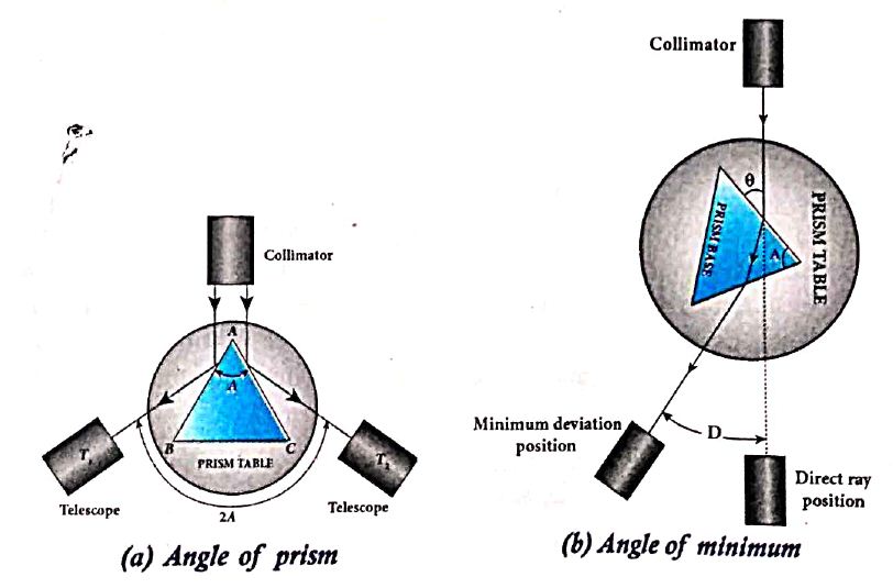
i) Angle of the prism (A):
(i) The prism is placed on the prism table with its refracting angle (A) facing the collimator as shown in Figure (a).
(ii) The slit is illuminated by sodium light (monochromatic light)
(iii)The parallel rays coming from the collimator fall on the two faces AB and AC and get reflected.
(iv) The telescope is rotated to the position T1 and T2 to capture the reflected rays and the two reading are noted
(v) The difference between these two readings gives the angle rotated by the telescope, which is twice the angle of the prism.
(vi) Half of this value gives the angle of the prism A.
ii) Angle of minimum deviation (D):
(i) The prism is placed on the prism table so that the light from the collimator falls on a refracting face, and the refracted image is observed through the telescope as shown in Figure.
(ii) The prism table is now rotated so that the angle of deviation decreases.
(iii) A stage comes when the image stops and returns on further rotation of the prism table.
(iv) This is ensured by looking through the telescope simultaneously. The reading in this position gives the minimum deviation position.
(v) Now, the prism is removed and the telescope is turned to receive the direct ray and the reading is noted.
(vi) The difference between the two readings gives the angle of minimum deviation D.
(vii) The refractive index of the material of the prism n is calculated using the formula,
\(\\ n=\cfrac { sin\left( \frac { A+D }{ 2 } \right) }{ sin\left( \frac { A }{ 2 } \right) } \) ..................(1)
The refractive index of a liquid may be determined in the same way using a hollow glass prism filled with the given liquid.
6.
(i) A simple microscope is a single magnifying (converging) lens of small focal length. To get an erect, magnified and virtual image of the object.
(ii) For this the object is placed between the focal length Fand P on one side of the lens and viewed from other side of the lens. There are two magnifications to be discussed for two kinds of focusing.
(a) Near point focusing:
The eye is least strained when image is formed at near point,i.e. 25 cm. The near point is also called as least distance of distinct vision. This is shown in Figure.
.JPG)
Magnification in near point focusing:
(i) Object distance u is less than f
(ii) The image distance is the near point D. The magnification m is given by the relation,
\(m=\cfrac { v }{ u } \) ...............(1)
Substituting, V = - D and u= - u, as both the distances are measured to the left of the lens. Hence,
\(m=\cfrac { -D }{ -u }\)
\(m=\cfrac { D }{ u } \) ...............(2)
Using lens equation, W.K.T, m = 1 - (v/f)
Substiuting v = -D gives, \(\\ m=1+\cfrac { D }{ f } \) ..................(3)
This is the magnification for near point focusing.
(b) Normal focusing :
(i) The eye is most relaxed when the image is formed at infinity. The focusing is called normal focusing when the image is formed at infinity. This is shown in Figure (b).
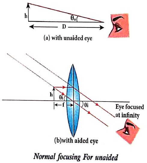
Magnification in normal focusing (angular magnification):
(ii) The angular magnification is defined as the ratio of angle θ1 subtended by the image with aided eye to the angle θ0 subtended by the object with unaided eye.
\(m=\cfrac { { \theta }_{ 1 } }{ { \theta }_{ 0 } } \) .........(2)
For unaided eye shown in Figure (a),
\(tan\theta _{ 0 }\approx { \theta }_{ 1 }=\cfrac { h }{ D } \) ................(3)
For aided eye shown in Figure(b).
\(tan\theta _{ i }={ \theta }_{ i }=\cfrac { h }{ f } \) ...................(4)
The angular magnification is,
\(m=\cfrac { { \theta }_{ i } }{ { \theta }_{ o } } =\cfrac { h/f }{ h/D } \)
\(m=\cfrac { D }{ f } \) ..............(5)
This is the magnification for normal focusing.
7.
(i) The effect of diffraction has an adverse effect in the sharpness of the image tormed.
(ii) There is always a spread of central maximum in the image for every point of the object, for every point of the object acts as a point source.
(iii) The condition for central maximum (or first minimum) produced by rectangular slit is given by the equation,
\(a \sin \theta=\lambda\) ....(1)
(iv) But, a circular slit (aperture) produces diffraction pattern of concentric circles as shown in Figure.
(v) These are known as Airy's discs. Most of the optical instruments form images of objects only through the circular slits.
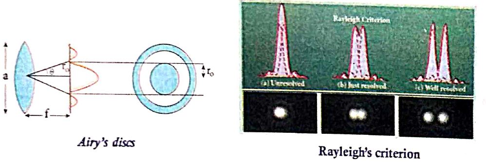
(vi) The condition for central maximum (or) first minimum for circular slit is,
\(\text { a } \sin \theta=1.22 \lambda\) .....(2)
(vii) Here, the numerical value 1.22 appears in the expression for central maximum (or) first minimum formed by circular slits.
For small angles,\(sin\theta = \theta\), the above equation becomes,
\(a\theta = 1.22\lambda\)
Rewriting further,
\(\theta=\frac{1.22 \lambda}{a}\) ......(3)
Form thegeometry, \(\theta=\frac{r_0}{f}\)
Substituting for in equation (3) and rearranging gives
\(r_0=\frac{1.22 \lambda f}{a}\) ....(4)
(viii) For example, let two point-sources of light close to cach other form image on a screen. The diffraction pattern of one point-source may overlap with another and produce a blurred image (or) un-resolved image as shown in Figure (a). To obtain a quality image (or) well resolved image, the two point-sources must be kept apart in such a way that their diffraction patterns do not overlap as shown in Figure (c).
(ix) According to Rayleigh's criterion, the two points on an image are said to be just resolved when the central maximum of one diffraction pattern coincides with the first minimum of the other and vice-versa as shown in Figure (b).
8.
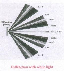
(i) Thediffraction pattern for white light consists of a white central maximum and on both side continuous coloured diffraction pattenrs are formed.
(ii) The central maximum is white as all the colours constructively meet at centre with no path difference. As \(\theta\) increases, the path difference fuifills the condition for maxima of different orders for all colours from violet to red.
(iii) It produces a spectrum of diffraction pattern from violet to red on either side of central maximum as shown in Figure.
(iv) By measuring the angle at which these colours appear for various orders of diffraction, the wavelength of different colours could be calculated using the formula.
\(\lambda =\cfrac { sin\theta }{ Nm } \)
(v) Here, N is the number of rulings per metre in the grating and m is the order of the diffraction image.
9.
(i) The wavelength of a spectral line can be very accurately determined with the help of a diffraction grating. For that we need to use an instrument called spectrometer.
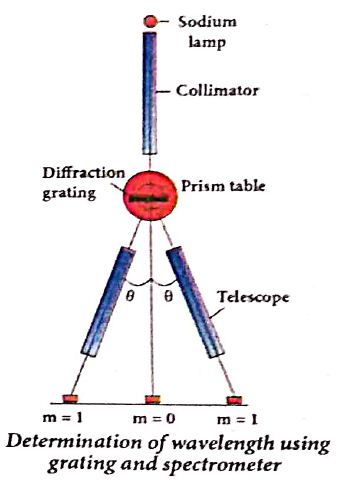
(ii) The slit of collimator is illuminated by a monochromatic light, whose wavelength is to be determined.
(iii) The telescope is brought in line with collimator to view the image of the slit.
(iv) The given plane transmission grating is then mounted on the prism table with its plane perpendicular to the incident beam of light coming from the collimator.
(v)The telescope is turned to one side until the first order diffraction image of the slit coincides with the vertical cross wire of the eye piece.
(vi) The reading of the position of the telescope is noted.
(vii) Similarly the first order diffraction image on the other side is made to coincide with the vertical cross wire and corresponding reading is noted.
(viii) The difference between two positions gives 2θ. Half of its value gives θ, the diffraction angle for first order maximum as shown in Figure.
The wavelength of light is calculated from the equation.
\(\\ \lambda =\cfrac { sin\theta }{ Nm } \)
(ix) Here, N is the number of rulings per metre in the grating and m is the order of the diffraction image.
10.
(i) Gratting has multiple slits with equal widths of size comparable to the wavelength of diffracting light.
(ii) Grating is a plane sheet of transparent material on which opaque rulings are made with a fine diamond pointer.
(iii) The modern commercial grating contains about 6000 lines per centimeter. The rulings act as obstacles having a definite width b and the transparent space between the rulings act as slit of width a.
(iv) The combined width of a ruling and a slit is called Gratting element (e = a + b).
(v) points on slit separated by a distance equal to the grating element are called corresponding points.
(vi) A plane transmission grating is represented by AB in Figure. Let a plane wavefront of monochromatic light with wavelength λ be incident on the grating.
(vii) As the width of the slits is comparable to that of wavelength, the incident light undergoes diffraction.
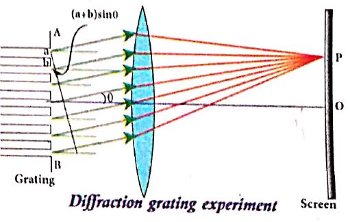
(viii) A diffraction pattern is obtained on the screen when the diffracted waves are focused on a screen using a convex lens.
(ix) Let us consider a point P at an angle θ with the perpendicular drawn from the center of the grating to the screen.
(x) The path difference ઠ between the diffracted waves from one pair of corresponding points is,
\(\delta =(a+b)sin\theta \) ........(1)
This path difference is the same for any pair of corresponding points. The point P on the screen will be maximum, when
ઠ= m λ where m = 0,1,2,3 ........(2)
Combining the above two equations, we get,
(a + b) sin θ = mλ ...............(3)
Here, m is called order of diffraction.
Condition for mth order maximum :
(i) On the side of central maxima different higher orders of diffraction maxima are formed at different angular positions. If we take,
\(N=\cfrac { 1 }{ a+b } \) .................(4)
(ii) Then, N gives the number of grating elements or rulings drawn per unit width of the grating. Normally, this number N is specified on the grating itself. Now, the equation becomes,
\(\cfrac { 1 }{ N } sin\theta =m\lambda \) (or) \(sin\theta =Nm\lambda \) ...............(5)
11.
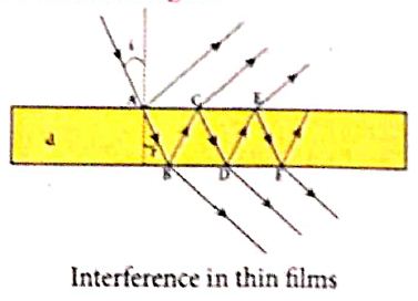
For transmitted light :
(i) The light transmitted may interfere to produce a resultant intensity. Consider the path difference between the two light waves transmitted from B and D.
(ii) The two waves moved together and remained in phase up to B where splitting occurred.
The extra path travelled by the wave transmitted from D is the path inside the film, BC + CD.
(iii) If we approximate the incidence to be nearly normal (i = 0), then the points B and D are very close to each other.
(iv) The extra distance travelled by the wave is approximately twice thickness of the film, BC + CD = 2d. As this extra path is traversed inside the medium of refractive index m, the optical path difference is, d = 2μd.
(v) The condition for constructive interference in transmitted ray is,
\(2\mu d=n\lambda \) .....(1)
(vi) Similarly, the condition for destructive interference in transmitted ray is,
\(2\mu d=\left( 2n-1 \right) \cfrac { \lambda }{ 2 } \) .....(2)
For reflected light:
(i) It is experimentally and theoretically proved that a wave while travelling in a rarer medium and getting reflected by a denser medium, undergoes a phase change of π.
(ii) Hence, an additional path difference of \(\cfrac { \lambda }{ 2 } \) should be considered for reflected light.
(iii) Let us consider the 2 path difference between the light waves reflected by the upper surface at A and the other wave coming out at C after passing through the film.
(iv) The additional path travelled by wave coming out from C is the path inside the film, AB + BC. For nearly normal incidence this distance could be approximated as, AB + BC = 2d.
(v) As this extra path is travelled in the medium of refractive index μ, the optical path difference is, ઠ = 2μd.
(vi)The condition for constructive interference for reflected ray is,
\(2\mu d+\cfrac { \lambda }{ 2 } =n\lambda \) (or) \(2\mu d=\left( 2n-1 \right) \cfrac { \lambda }{ 2 } \) .....(3)
(vii) The additional path difference \(\cfrac { \lambda }{ 2 } \) is due to the phase change of π in rarer to denser reflection taking place at A.
(viii) The condition for destructive interference for reflected ray is
\(2\mu d+\cfrac { \lambda }{ 2 } =\left( 2N+1 \right) \cfrac { \lambda }{ 2 } \) (or) \(2\mu d=n\lambda \) ....(4)
12.
Experimental setup:
(i) S is a source s1 and s2 the double slits which are at equidistances from 's'. Wavefronts from s1 and s2 spread out and overlap on other side of double slit.
(ii) When a screen is placed at a distance of about 1 meter from the slits, alternate bright and dark fringes which are equally spaced appear on the screen. These are called interference fringes or bands.
(iii) Using an eyepiece the fringes can be seen directly. At the center point O on the screen, waves from s1 and s2 travel equal distances and arrive in-phase as shown in Figure.
(iv) These two waves constructively interfere and bright fringe is observed at O. This is called cental bright fringe.
(v) When one of the slits is closed, The fringes disappear and there in uniform illumination on the screen.
(vi) This shows clearly that the bands are due to interference.
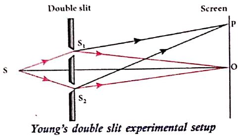
Equation for path difference :
(i) The Let d be the distance between the double slits s1 and s2 which act as coherent sources of wavelength λ.
(ii) A screen is placed parallel to the double slit at a distance D from it.
(iii) P is any point at a distance y from O.
(iv) The waves from S1 and S2 meet at P either in-phase or out-of-phase depending upon the path difference between the two waves.
.JPG)
The path difference \(\delta\) between the light waves from s1 and s2 to the point p is,
\(\delta=\mathrm{S}_{2} \mathrm{P}-\mathrm{S}_{1} \mathrm{P}\)
\(\delta=\mathrm{S}_{2} \mathrm{P}-\mathrm{MP}=\mathrm{S}_{2} \mathrm{M}\) .........(1)
\(\angle \mathrm{OCP}=\angle \mathrm{S}_{2} \mathrm{~S}_{1} \mathrm{M}=\theta\)
In right angle triangle \(\Delta \mathrm{S}_{1} \mathrm{S}_{2} \mathrm{M}\), the path difference S2M = d sin \(\theta\)
\(\delta=d \sin \theta\) ...........(2)
If the angle \(\theta\) is small, \(\sin \theta \approx \tan \theta \approx \theta\)
From the right angle triangle \(\Delta \mathrm{OCP}, \tan \theta=\frac{\mathrm{y}}{\mathrm{D}}\)
The path differences \(\delta=\frac{d y}{D}\) ...........(3)
Based on the condition of the path difference, the point P may have a bright (or) dark fringe
13.
Let us Consider two light waves from the two sources SI and S2 meeting at a point P as shown in figure
The wave from SI at an instant t at P is,
y1= a1 sin ω t ...................(1)
The wave form S2 at an instant t at P is,
y2= a2 sin (ωt + Φ) .............(2)
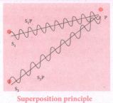
The two waves have different amplitudes al and a2 , same angular frequency ω, and a phase difference of \(\phi\)
y = y1 + y2 = a1 = a\sin ωt + a1sin2 (ωt + Φ) ............(3)
The simplification of the above equation by using trigonometric identities,
\(y=Asin\left( \omega t+\theta \right) \) ..............(4)
where, \(A=\sqrt { { a }_{ 1 }^{ 2 }+{ a }_{ 2 }^{ 2 }+2{ a }_{ 1 }{ a }_{ 2 }cos\phi } \) ..................(5)
\(\theta ={ tan }^{ -1 }\cfrac { { a }_{ 2 }sin\phi }{ { a }_{ 1 }+{ a }_{ 2 }cos\phi } \) ..................(6)
The resultant amplitude is maximum,
\({ A }_{ max }=\sqrt { \left( { a }_{ 1 }+{ a }_{ 2 } \right) ^{ 2 } } \) ; When Φ = 0,± 2π , ± 4π... ................(7)
The resultant amplitude is minimum
\({ A }_{ min }=\sqrt { \left( { a }_{ 1 }+{ a }_{ 2 } \right) ^{ 2 } } \); When Φ = ±π, ± 3π, ± 5π..., ............(8)
The intensity of light is proportional to square of amplitude,
I ∝ A2 ...........(9)
Now, equation (5) becomes,
\(1\infty { I }_{ 1 }+I_{ 2 }+2\sqrt { { I }_{ 1 }{ { I }_{ 2 } } } cos\phi \) ..........(10)
In equation (10) if the phase difference, f = 0, ± 2π, ± 4π ... , it corresponds to the condition for maximum intensity of light called as constructive interference.
The resultant maximum intensity is
\({ I }_{ max }\propto \left( { a }_{ 1 }+{ a }_{ 2 } \right) ^{ 2 }\propto { I }_{ 1 }{ I }_{ 2 }+2\sqrt { { \quad I }_{ 1 }{ I }_{ 2 } } \) ...............(11)
In equation (10) if the phase difference, Φ = ±π, ±3π, ± 5π ... , it corresponds to the condition for minimum intensity of light called destructive interference.
The resultant minimum intensity is,
\({ I }_{ min }\propto \left( { a }_{ 1 }+{ a }_{ 2 } \right) \propto { I }_{ 1 }+{ I }_{ 2 }2\sqrt { { I }_{ 1 }{ I }_{ 2 } } \) ................(12)
As a special case, if a1 = a2 = a, then equation (5) becomes
\(A=\sqrt{2 a^{2}+2 a^{2} \cos \phi} =\sqrt{2 a^{2}(1+\cos \theta)} \)
\(=\sqrt{2 a^{2} 2 \cos ^{2}\left(\frac{\phi}{2}\right)} \)
\(\mathrm{A}=2 \mathrm{a} \cos (\phi / 2) \) ........(13)
\(\mathrm{I} \alpha 4 \mathrm{a}^{2} \cos ^{2}(\phi / 2)\left[\therefore \mathrm{I} \alpha \mathrm{A}^{2}\right] \) ..............(14)
\(\mathrm{I}=4 \mathrm{I}_{0} \cos ^{2}(\phi / 2)\left[\therefore \mathrm{I}_{0} \alpha \mathrm{a}^{2}\right] \) ...............(15)
\(\mathrm{I}_{\max }=4 \mathrm{I}_{0} \text { when, } \phi=0, \pm 2 \pi, \pm 4 \pi \ldots . \) ...............(16)
\(\mathrm{I}_{\min }=0 \text { when, } \phi=\pm \pi, \pm 3 \pi, \pm 5 \pi \ldots . \) .............(17)
14.
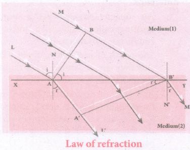
(i) Let us Consider a parallel beam of light is incident on a refracting plane surface XY such as a glass surface as shown in Figure.
(ii) The incident wavefront AB is in rarer medium (1) and the refracted wavefront A'B' is in denser medium (2).
(iii) These wavefronts are perpendicular to the incident rays L, M and refracted rays L', M' respectively.
\(t=\cfrac { BB' }{ { v }_{ 1 } } =\cfrac { AA' }{ { v }_{ 2 } } \) or \(\cfrac { BB' }{ AA' } =\cfrac { { v }_{ 1 } }{ { v }_{ 2 } } \)
(i) The incident rays, the refracted rays and the normal are in the same plane.
(ii) Angle of incidence
i = ∠ NAL = 90o - ∠NAB = ㄥ BAB'
Angle of refraction,
r = ∠ N'B'M = 90o-ㄥN'B'A' =∠ A'B'A
For the two right angle triangles ∆ABB' and ∆AA'B',
\(\cfrac { sini }{ sinr } =\cfrac { \frac { BB' }{ AB' } }{ \frac { AA' }{ AB' } } =\cfrac { BB' }{ AA' } =\cfrac { { v }_{ 1 } }{ { v }_{ 2 } } =\cfrac { \frac { c }{ { v }_{ 2 } } }{ \frac { c }{ { v }_{ 1 } } } \)
(iv) Here, C is speed of light in vacuum. The ratio \(\cfrac { c }{ v } \) is the constant, called refractive index of the medium. The refractive index of medium (1) is,\(\cfrac { c }{ { v }_{ 1 } } ={ n }_{ 1 }\) and that of medium (2) is,\(\cfrac { c }{ { v }_{ 1 } } ={ n }_{ 2 }\) In ratio form,
\(\cfrac { sini }{ sinr } =\cfrac { { n }_{ 2 } }{ { n }_{ 1 } } \) .............(1)
In product form,
n1 sin i = n2 sin r ..........(2)
Hence, the laws of refraction are proved.
15.
(i) Let us consider a parallel beam of light, incident on a reflecting plane surface such as a plane mirror XY.
(ii) The incident wavefront is AB and the reflected waterfront is A'B'.
(iii) These wavefronts are perpendicular to the incident rays L, M and reflected rays L', M', respectively.
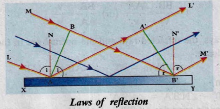
(i) The incident rays, the reflected rays and the normal are in the same plane.
(ii) Angle of incidence, ∠i = ∠NAL = 90°- ∠NAB = ∠BAB'
Angle of reflection ∠r = ∠N'B'M = 90°- ∠N'B'A'= ∠A'B'A
(a) For the two right angle triangles, ∆ABB' and ∆B'A'A, the two right angles, ∠B and ∠A' are equal, (∠B and ∠A' = 90°); the two sides., AA' and BB' are equal, (AA' = BB'); the side AB' is common
(b) Thus the two triangles are congruent. As per the property of congruency, the two angles, ∠BAB' and ∠A'B'A must also be equal.
i = r
Hence, the laws of reflection are proved.
16.
(i) An astronomic telescope used to get the magnification of distant astronomical objects like stars, planets, moon etc.
(ii) The image formed by astronomicaltelescope willbe inverted. It has an objective of long focal length and a much larger aperture than the eyepiece as shown in Figure.
(iii) Light from a distant object enters the objective and a real image is formed in the tube at its second focal point.
(iv) The eyepiece magnifies this image producing a final inverted image.
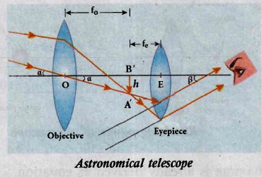
Magnification of astronomical telescope:
The magnification m is the ratio of the angle β subtended by the image to the angle α which subtended by the object with the principal axis
\(m=\cfrac { \beta }{ \alpha } \) ......(1)
From the diagram, ,\(\alpha=\frac{h}{f_e} \ and \ \beta=\frac{h}{f_e}\) ...................(2)
\(m=\cfrac { { f }_{ 0 } }{ { f }_{ e } } \) .........................(3)
The length of the telescope is approximate, L = f0 + fe.
17.
(i) It forms a real, inverted and magnified image of the object. This serves as the object for the lens close to the eye called as eyepiece.
(ii) The eyepiece serves as a simple microscope that produces finally an enlarged and virtual image.
(iii) The first inverted image formed by the objective is to be adjusted within the focus of the eyepiece so that the final image is formed nearly at infinity (or) at the near point.
(iv) The final image is inverted with respect to the object
Magnification of compound microscope:
(i) From the ray diagram, the linear magnification due to the objective is,
\({ M }_{ 0 }=\cfrac { h' }{ h } \) ..............(1)
From the Figure,\(tan\beta =\cfrac { h }{ { f }_{ 0 } } =\cfrac { h' }{ L } \) then
\(\cfrac { h' }{ h } =\cfrac { L }{ { f }_{ 0 } } \) ...............(2)
\({ m }_{ 0 }=\cfrac { L }{ { f }_{ 0 } } \) ..............(3)
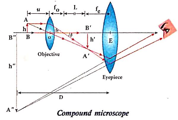
(ii) Here, the distance L is between the first focal point of the eyepiece to the second focal point of the objective. This is called the tube length of the microscope as f0 and fe are comparatively smaller than L.
(iii) If the final image is formed at (near point focussing); the magnification (me) of the eyepiece is,
\({ m }_{ e }=1+\cfrac { D }{ { f }_{ e } } \) ..............(4)
The total magnification m in near point focusing is,
\(m={ m }_{ 0 }{ m }_{ e }\left( \cfrac { L }{ { f }_{ 0 } } \right) \left( 1+\cfrac { D }{ { f }_{ e } } \right) \) ...............(5)
If the final image is formed at infinity (normal focusing), the magnification me of the eyepiece is,
\({ m }_{ e }=\cfrac { D }{ { f }_{ e } } \) ......................(6)
The total magnification m in normal focusing is,
\(m=m_{ 0 }{ m }_{ e }=\left( \cfrac { L }{ { f }_{ 0 } } \right) \left( \cfrac { D }{ { f }_{ e } } \right) \) ....................(7)

12th Standard Syllabus & Materials
12th Standard
TN 12th Computer Applications களப்பெயர் முறைமை (DNS) Sample Question Papers Study Material - QB365 Set A
NEW12th Standard
TN 12th Computer Applications வலையமைப்பு எடுத்துக்காட்டுகள் மற்றும் நெறிமுறைகள் Sample Question Papers Study Material - QB365 Set A
NEW12th Standard
TN 12th Computer Applications கணினி வலையமைப்பு ஓர் அறிமுகம் Sample Question Papers Study Material - QB365 Set A
NEW12th Standard
TN 12th Computer Applications PHP-உடன் MySQL-ஐ இணைத்தல் Sample Question Papers Study Material - QB365 Set A



Tamilnadu Stateboard 12th Standard Subjects

Maths

Chemistry
Physics

Biology

Computer Science

Business Maths and Statistics

Economics

Commerce

Accountancy

History

Computer Applications
Biology
Computer Technology
Computer Applications
Computer Science
Business Maths and Statistics
Commerce
Economics
Maths
Chemistry
Physics
Computer Technology
History
Accountancy

Tamil

English

French
Tamilnadu Stateboard Standards

