
 100% FREE ACCESS
12th Standard Syllabus & Materials
12th Standard
TN 12th Computer Applications மின்னணு தரவு பரிமாற்றம் Sample Question Papers Study Material - QB365 Set A
NEW12th Standard
TN 12th Computer Applications மின் - வணிக பாதுகாப்பு அமைப்புகள் Sample Question Papers Study Material - QB365 Set A
NEW12th Standard
TN 12th Computer Applications மின்னணு செலுத்தல் முறைகள் Sample Question Papers Study Material - QB365 Set A
NEW12th Standard
TN 12th Computer Applications மின் - வணிகம் Sample Question Papers Study Material - QB365 Set A
NEW12th Standard
TN 12th Computer Applications திறந்த மூல கருத்துருக்கள் Sample Question Papers Study Material - QB365 Set A
NEW12th Standard
TN 12th Computer Applications வலையமைப்பு வடமிடல் Sample Question Papers Study Material - QB365 Set A

Published on: 30/09/2019
Magnetism and Magnetic Effects of Electric Current
Download Tamil Nadu 12th Standard Physics question papers, model tests, one-mark questions, important questions, and public exam papers in PDF format. Free study materials and answer keys for TN State Board students.
Questions + Answers key
Take MCQ Physics Test1.
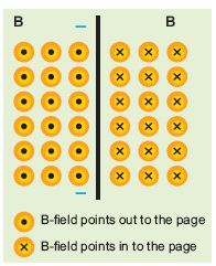
The magnetic field shown in the figure is due to the current carrying wire. In which direction does the current flow in the wire?
2.
Using the relation \(\overset { \rightarrow }{ B } =\mu _{ ° }(\overset { \rightarrow }{ H+ } \overset { \rightarrow }{ M } )\) show that \({ x }_{ m }={ \mu }_{ r }-{ 1 }\)
3.
The repulsive force between two magnetic poles in air is 9 x 10⁻³ N. If the two poles are equal in strength and are separated by a distance of 10 cm, calculate the pole strength of each pole.
4.
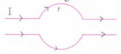
What is the value of the magnetic field at point O due to a current flowing in the wires?
5.
Obtain an expression for magnetic Lorentz force?
6.
State that a current carrying loop behaves as a magnetic dipole. Hence write an expression for its magnetic dipole moment.
7.
Compute the intensity of magnetisation of the bar magnet whose mass, magnetic moment and density are 200 g, 2 A m2 and 8 g cm–3, respectively.
8.
A short bar magnet has a magnetic moment of 0.5 J T–1. Calculate magnitude and direction of the magnetic field produced by the bar magnet which is kept at a distance of 0.1 m from the centre of the bar magnet along
(a) axial line of the bar magnet and
(b) normal bisector of the bar magnet.
9.
Discuss the conversion of galvanometer into an ammeter and also a voltmeter.
10.
Explain the principle and working of a moving coil galvanometer.
1.
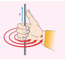
Using right hand rule, current flows upwards.
2.
\(\overset { \rightarrow }{ B } =\mu _{ ° }(\overset { \rightarrow }{ H+ } \overset { \rightarrow }{ M } )\)
But from equation (3.33), in vector form,
\(\overset { \rightarrow }{ M } ={ x }_{ m }\overset { \rightarrow }{ H } \)
Hence, \(\overset { \rightarrow }{ B } =\mu _{ ° }({ x }_{ m }+1)\overset { \rightarrow }{ H } \Rightarrow \overset { \rightarrow }{ B } =\mu \overset { \rightarrow }{ H } \)
where, \(\mu =\mu _{ ° }({ x }_{ m }+1)\Rightarrow { x }_{ m }+1=\frac { \mu }{ \mu _{ ° } } =\mu _{ r }\)
\(\Rightarrow { x }_{ m }=\mu _{ r }-1\)
3.
The magnitude of the force between two poles is given by
\( F =k\frac { { q }_{ m_A }{ q }_{ { m }_{ B } } }{ { r }^{ 2 } } \)
(Given : F = 9 × 10⁻³ N, r = 10 cm = 10 × 10–2 m
Since qmA = qmB = qm, we have
9 x 10-3 = 10-7 x \(\frac { { q }_{ m }^{ 2 } }{ { \left( 10\times { 10 }^{ -2 } \right) }^{ 2 } } \Rightarrow { q }_{ m }\) = 30NT-1
4.
The magnetic field at point O is zero. Because the upper and lower current carrying conductors are identical and so the magnetic fields caused by them at centre O will be equal and opposite.
5.
When an electric charge q is moving with velocity \(\vec { v } \) in the magnetic field \(\vec { B } \), it experiences a force, called magnetic force \(\vec { { F }_{ m } } \). After careful experiments, Lorentz deduced the force experienced by a moving charge in the magnetic field \(\vec { { F }_{ m } } \).
\(\vec { { F }_{ m } } =q(\vec { v } \times \vec { B } )\) ...........(1)
In magnitude, Fm = qvB sinθ .......(2)
The equations (1) and equation (2) imply
(i) \(\vec { { F }_{ m } } \) is directly proportional to the magnetic field \(\vec { B } \).
(ii) \(\vec { { F }_{ m } } \) is directly proportional to the velocity \(\vec { v } \).
(iii) \(\vec { { F }_{ m } } \) is directly proportional to sine of the angle between the velocity and magnetic field.
(iv) \(\vec { { F }_{ m } } \) is directly proportional to the magnitude of the charge q.
(v) The-direction of \(\vec { { F }_{ m } } \) is always perpendicular to \(\vec { v } \) and B as \(\vec { { F }_{ m } } \) in the cross product of \(\vec { v } \) and \(\vec { B } \).
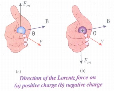
(vi) The direction of \(\vec { { F }_{ m } } \) on a negative charge is opposite to the direction of \(\vec { { F }_{ m } } \) on positive charge provided other factors are identified as shown in Figure.
(vii) If the velocity \(\vec { v } \) of the charge, q is along the magnetic field \(\vec { B } \) then, \(\vec { { F }_{ m } } \) is zero.
6.
The magnetic field from the center of a circular loop of radius R along the axis is given by
\(\vec { B } =\frac { { \mu }_{ 0 }I }{ 2 } \frac { { R }^{ 2 } }{ ({ R }^{ 2 }+{ z }^{ 2 })^{ \frac { 3 }{ 2 } } } \hat { k } \)
At larger distance z >> R, therefore R2 + z2 ≈ z2,
we have
\(\vec { B } =\frac { { \mu }_{ 0 }I }{ 2 } \frac { { R }^{ 2 } }{ { z }^{ 3 } } \hat { k } \) ........(1)
Let A be the area of the circular loop A = πR2. So rewriting the equation (1) in terms of the area of the loop, we have
\(\vec { B } =\frac { { \mu }_{ 0 }I }{ 4\pi } \frac { { R }^{ 2 } }{ { z }^{ 3 } } \hat { k } \)
\(\vec { B } =\frac { { \mu }_{ 0 } }{ 4\pi } \frac { 2IA }{ { z }^{ 3 } } \hat { k } \) .......(2)
Comparing equation (2) with equation (1) dimensionally, we get
pm = IA
where Pm is called a magnetic dipole moment. In vector notation,
\(\vec { { p }_{ m } } =I\vec { A } \) .........(3)
This implies that a current - carrying circular loop behaves as a magnetic dipole of the magnetic moment \(\vec { { p }_{ m } } \) So, the magnetic dipole moment of any current loop is equal to the product of the current and area of the loop.
7.
Density of the magnet is
Density = \(\frac { Mass }{ volume } \Rightarrow Volume=\frac { Mass }{ Density } \)
\(Volume=\frac { 200\times 1{ 0 }^{ -3 }kg }{ \left( 8\times 1{ 0 }^{ -3 }kg \right) \times 1{ 0 }^{ 6 }{ m }^{ -3 } } =25\times { 10 }^{ -6 }{ m }^{ 3 }\)
Magnitude of magnetic moment pm = 2A m2
Intensity of magnetization,
\(I=\frac { magnetic\ moment }{ Volume } =\frac { 2 }{ 25\times { 10 }^{ -6 } } \)
M = 0.8 x 10⁵ Am-1
8.
Given magnetic moment 0.5 J T-1 and distance r = 0.1 m
(a) When the point lies on the axial line of the bar magnet, the magnetic field for short magnet is given by
\({ { \vec B }_{ axial } } =\frac { { \mu }_{ ° } }{ 4\pi } \left( \frac { 2{ p }_{ m } }{ { r }^{ 3 } } \right) \hat { i } \)
\({ { \vec B }_{ axial } } =1{ 0 }^{ -7 }\times \left( \frac { 2\times 0.5 }{ { \left( 0.1 \right) }^{ 3 } } \right) =1\times { 10 }^{ -4 }\hat { i } \ T\)
Hence, the magnitude of the magnetic field along axial is Baxial = 1 x 10⁻⁴ T and direction is towards South to North.
(b) When the point lies on the normal bisector (equatorial) line of the bar magnet, the magnetic field for short magnet is given by
\({ {\vec B }_{ equatorial } } =-\frac { { \mu }_{ ° } }{ 4\pi } \frac { { p }_{ m } }{ { r }^{ 3 } } \hat { i } \)
\({ {\vec B }_{ equatorial } } =-1{ 0 }^{ -7 }\left( \frac { 0.5 }{ { \left( 0.1 \right) }^{ 3 } } \right) \hat { i } =-0.5\times 1{ 0 }^{ -4 }\hat { i } \ T \)
Hence, the magnitude of the magnetic field along axial is Bequatorial = 0.5 x 10⁻⁴ T and direction is towards North to South.
Note that magnitude of Baxial is twice that of magnitude of Bequatorial and the direction of Baxial and Bequatorial are opposite.
9.
(i) Galvanometer to an Ammeter:
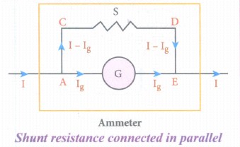
(i) Ammeter is an instrument used to measure current flowing in the electrical circuit.
(ii) The Ammeter must offer low resistance such that it will not change the current passing through it. So, ammeter is connected in series to measure the circuit current.
(iii) A galvanometer is converted into an ammeter by connecting a low resistance in parallel with the galvanometer.
(iv) Let I be the current passing through the circuit. When current I reaches the junction A, it divides into two components.
a) Ig → Current passing through the galvanometer
b) I - Ig → Current passing through the shunt resistance.
(v) The potential difference across the galvanometer is same as the potential difference across the shunt resistance.
\(\mathrm{V}_{\text {galvanometer }} =\mathrm{V}_{\text {shunt }} \)
\(\Rightarrow \mathrm{I}_{\mathrm{g}} \mathrm{R}_{\mathrm{g}} =\left(\mathrm{I}-\mathrm{I}_{g}\right) \mathrm{S} \)
\(\mathrm{S} =\frac{I_{g}}{\left(I-I_{g}\right)} R_{g} \) (or)
\(\mathrm{I}_{\mathrm{g}}=\frac{S}{S+R_{g}} I \Rightarrow I_{g} \propto I\)
Since, the deflection in the galvanometer is proportional to the current passing through it.
\(\theta=\frac{1}{G} I_{g} \Rightarrow \theta \propto I_{g} \Rightarrow \theta \propto I\)
Where, Rg → Galvanometer resistance, S → Shunt resistance.
Since shunt resistance is connected in parallel to galvanometer,
Effective resistance,\(\frac{1}{R_{e f f}}=\frac{1}{R_{g}}+\frac{1}{S} \Rightarrow R_{e f f}=\frac{R_{g} S}{R_{g}+S}=R_{a}\)
Ra ⇒ low resistance. An ideal ammeter has zero resistance.
The percentage error in measuring a current through an ammeter is,
\(\frac{\Delta I}{I} \times 100 \%=\frac{I_{i d e a l}-I_{a c t u a l}}{I_{a c t u a l}} \times 100 \%\)
(ii) Galvanometer to a voltmeter:
i) A voltmeter is an instrument used to measure potential difference across any two points in the electrical circuits.
ii) Voltmeter must have high resistance and when it is connected in parallel, it will rot draw appreciable current so that it will indicate the true potential difference.
iii) A galvanometer is converted into a voltmeter by connecting high resistance Rh in series with galvanometer.
iv) Let Rg be the resistance of galvanometer and Ig be the current with which the galvanometer produces full scale deflection.
v) Since the galvanometer is connected in series with high resistance, the current in the electrical circuit is same as the current passing through the galvanometer.
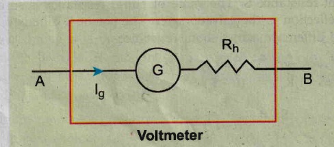
\(\mathrm{I}=\mathrm{I}_{\mathrm{g}} \)
\(\mathrm{I}=I_{g} \Rightarrow I_{g}=\frac{\text { potential difference }}{\text { total resistance }} \)
Since the galvanometer and high resistance are connected in series, the voltmeter resistance is,
\(R_{v} =R_{g}+R_{h} \)
Therefore,
\(I_{g} =\frac{V}{R_{g}+R_{h}} \)
\(\Rightarrow R_{h} =\frac{V}{I_{g}}-R_{g} \)
Note that \(I_{g} \propto V\)
Rh is very large. An ideal voltmeter has infinite resistance
10.
Principle : When a current carrying loop is placed in a uniform magnetic field it experiences a torque.
Construction : A moving coil galvanometer consists of a rectangular coil PQRS of insulated thin copper wire. The coil contains a large number of turns wound over a light metallic frame. A cylindrical soft-iron core is placed symmetrically inside the coil as shown in Figure. The rectangular coil is suspended freely between two pole pieces of a horse-shoe magnet.
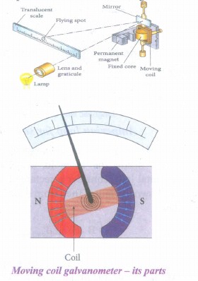
The upper end of the rectangular coil is attached to one end of fine strip of phosphor bronze and the lower end of the coil is connected to a hair spring which is also made up of phosphor bronze. In a fine suspension strip, a small plane mirror is attached in order to measure the deflection of the coil with the help of lamp and scale arrangement. The other end of the mirror is connected to a torsion head. In order to pass electric current through the galvanometer, the suspension strip and the spring S are connected to terminals.
Working : Consider a single turn of the rectangular coil PQRS whose length be l and breadth b. PQ = RS = l and QR = SP = b.
Let I be the electric current flowing through the rectangular coil PQRS as shown in Figure. The horse-shoe magnet has hemi - spherical magnetic poles which produces a radial magnetic field. Due to this radial field, the sides QR and SP are always parallel to the magnetic field B and experience no force. The sides PQ and RS are always parallel to the magnetic field and experience force in opposite directions. Due to this, torque is produced.
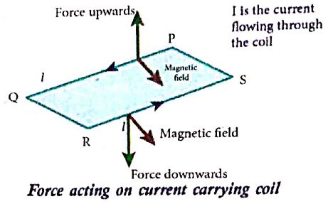
For single turn, the deflection torque is,
て = bF = bBIl = (lb)BI
て = ABI
since, area of the coil A = lb
For coil with N turns, we get
て = NABI ........(1)
Due to this deflecting torque, the coil gets twisted and restoring torque (also known as restoring couple) is developed. Hence the moment of restoring couple is proportional to the amount of twist θ. Thus
て = Kθ ............(2)
where K is the restoring couple per unit twist or torsional constant of the spring.
At equilibrium, the deflection couple is equal to the restoring couple. Therefore by comparing equations (1) and (2), we get,
NABI = Kθ
⇒ I =\(\frac { K }{ NAB } \) θ ...........(3)
(or) I = Gθ
where G = \(\frac { K }{ NAB } \) is called galvanometer constant or current reduction factor of the galvanometer.
Since, suspended moving coil galvanometer is very sensitive, we have to handle with high care while doing experiments. Most of the galvanometer we use are pointer type moving coil galvanometer.

12th Standard Syllabus & Materials
12th Standard
TN 12th Computer Applications களப்பெயர் முறைமை (DNS) Sample Question Papers Study Material - QB365 Set A
NEW12th Standard
TN 12th Computer Applications வலையமைப்பு எடுத்துக்காட்டுகள் மற்றும் நெறிமுறைகள் Sample Question Papers Study Material - QB365 Set A
NEW12th Standard
TN 12th Computer Applications கணினி வலையமைப்பு ஓர் அறிமுகம் Sample Question Papers Study Material - QB365 Set A
NEW12th Standard
TN 12th Computer Applications PHP-உடன் MySQL-ஐ இணைத்தல் Sample Question Papers Study Material - QB365 Set A



Tamilnadu Stateboard 12th Standard Subjects

Maths

Chemistry
Physics

Biology

Computer Science

Business Maths and Statistics

Economics

Commerce

Accountancy

History

Computer Applications
Biology
Computer Technology
Computer Applications
Computer Science
Business Maths and Statistics
Commerce
Economics
Maths
Chemistry
Physics
Computer Technology
History
Accountancy

Tamil

English

French
Tamilnadu Stateboard Standards

