
 100% FREE ACCESS
12th Standard Syllabus & Materials
12th Standard
TN 12th Computer Applications மின்னணு தரவு பரிமாற்றம் Sample Question Papers Study Material - QB365 Set A
NEW12th Standard
TN 12th Computer Applications மின் - வணிக பாதுகாப்பு அமைப்புகள் Sample Question Papers Study Material - QB365 Set A
NEW12th Standard
TN 12th Computer Applications மின்னணு செலுத்தல் முறைகள் Sample Question Papers Study Material - QB365 Set A
NEW12th Standard
TN 12th Computer Applications மின் - வணிகம் Sample Question Papers Study Material - QB365 Set A
NEW12th Standard
TN 12th Computer Applications திறந்த மூல கருத்துருக்கள் Sample Question Papers Study Material - QB365 Set A
NEW12th Standard
TN 12th Computer Applications வலையமைப்பு வடமிடல் Sample Question Papers Study Material - QB365 Set A

Published on: 30/08/2019
Electrostatics
Download Tamil Nadu 12th Standard Physics question papers, model tests, one-mark questions, important questions, and public exam papers in PDF format. Free study materials and answer keys for TN State Board students.
Questions + Answers key
Take MCQ Physics Test1.
Rank the electrostatic potential energies for the given system of charges in increasing order
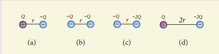
1 = 4 < 2 < 3
2 = 4 < 3 < 1
2 = 3 < 1 < 4
3 < 1 < 2 < 4
2.
Two identical conducting balls having positive charges q1 and q2 are separated by a centre to centre distance r. If they are made to touch each other and then separated to the same distance, the force between them will be _____.
less than before
same as before
more than before
zero
3.
The total electric flux for the following closed surface which is kept inside water
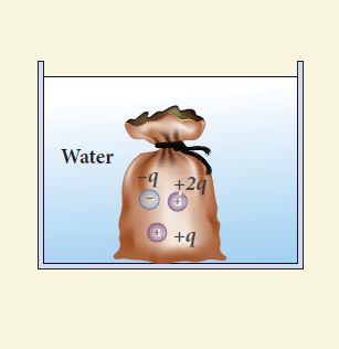
\(\frac { 80q }{ { \varepsilon }_{ 0 } } \)
\(\frac { q }{ { 40\varepsilon }_{ 0 } } \)
\(\frac { q }{ { 80\varepsilon }_{ 0 } } \)
\(\frac { q }{ { 160\varepsilon }_{ 0 } } \)
4.
5.
Two identical point charges of magnitude –q are fixed as shown in the figure below. A third charge +q is placed midway between the two charges at the point P. Suppose this charge +q is displaced a small distance from the point P in the directions indicated by the arrows, in which direction(s) will +q be stable with respect to the displacement?
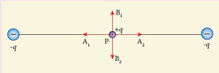
A1 and A2
B1 and B2
both directions
No stable
6.
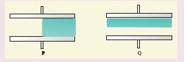
Capacitors P and Q have identical cross sectional areas A and separation d. The space between the capacitors is filled with a dielectric of dielectric constant εr as shown in the figure. Calculate the capacitance of capacitors P and Q.
7.
For the given capacitor configuration
(a) Find the charges on each capacitor
(b) potential difference across them
(c) energy stored in each capacitor
8.
During a thunder storm, the movement of water molecules within the clouds creates friction, partially causing the bottom part of the clouds to become negatively charged. This implies that the bottom of the cloud and the ground act as a parallel plate capacitor. If the electric field between the cloud and ground exceeds the dielectric breakdown of the air (3 x 10⁶ Vm-1 ), lightning will occur.
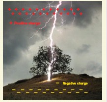
(a) If the bottom part of the cloud is 1000 m above the ground, determine the electric potential difference that exists between the cloud and ground.
(b) In a typical lightning phenomenon, around 25C of electrons are transferred from cloud to ground. How much electrostatic potential energy is transferred to the ground.
9.
What is corona discharge?
10.
Define ‘capacitance’. Give its unit.
11.
What is dielectric strength?
12.
What is polarisation?
13.
Write a short note on ‘electrostatic shielding’.
14.
An electron and a proton are allowed to fall through the separation between the plates of a parallel plate capacitor of voltage 5 V and separation distance h = 1 mm as shown in the figure.
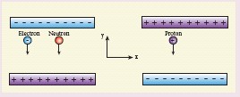
(a) Calculate the time of flight for both electron and proton
(b) Suppose if a neutron is allowed to fall, what is the time of flight?
(c) Among the three, which one will reach the bottom first? (Take mp = 1.6 x 10⁻²⁷ kg, me = 9.1 x 10⁻³¹ kg and g = 10 m s-2)
15.
Obtain the expression for energy stored in the parallel plate capacitor.
16.
Explain in detail the construction and working of a Van de Graaff generator.
17.
Explain in detail how charges are distributed in a conductor, and the principle behind the lightning conductor.
18.
Derive the expression for resultant capacitance, when capacitors are connected in series and in parallel.
19.
Explain in detail the effect of a dielectric placed in a parallel plate capacitor.
1.
\(U=\frac{1}{4\piε_0}\frac{q_1q_2}{r_{12}}\)
\(i) U=\frac{1}{4\piε_0}\frac{Q(-Q)}{r}=\frac{1}{4\piε_0}[\frac{-Q^2}{r}]\)
\(ii) U=\frac{1}{4\piε_0}\frac{(-Q)(-Q)}{r}=\frac{1}{4\piε_0}[\frac{Q^2}{r}]\)
\(iii) U=\frac{1}{4\piε_0}\frac{Q(2Q)}{r}=\frac{1}{4\piε_0}[\frac{2Q^2}{r}]\)
\(iv) U=\frac{1}{4\piε_0}\frac{Q(-2Q)}{2r}=\frac{1}{4\piε_0}[\frac{-Q^2}{r}]\)
From the values, 1 = 4 < 2 < 3
2.
Force ∝ charge
After the separation, the magnitude of charge will be increased. So the force will be more than before.
3.
\(Φ=\frac { q_{net} }{ { \varepsilon }_{ 0 } } \)
qnet = - q + q + 2q = 2q
Relative permittivity of water = 80
\(\therefore Φ=\frac { q }{{ \varepsilon }_{ r } { \varepsilon }_{ 0 } } \)
\(=\frac{2q}{{ 80 \times \varepsilon }_{ 0 }}=\frac{q}{{ 40 \varepsilon }_{ 0 }}\)
4.
(b)
5.
The charge + q will be stable between B1 and B2 with respect to the displacement.
6.
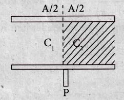
(a) \(C_{1}=\frac{\varepsilon_{0} A}{2d} (\because area=\frac{A}{2})\)
\(C_{2}=\frac{\varepsilon_{r} \varepsilon_{0} A}{d} \)
C1 and C2 are in parellel,
\(C_{P}=\left(C_{1}+C_{2}\right) \)
\(C_{P}=\frac{1}{2}\left(\frac{\varepsilon_{r} \varepsilon_{0} A}{d}+\frac{\varepsilon_{0} A}{d}\right) \)
\(=\frac{1}{2} \frac{\varepsilon_{0} A}{d}\left(\varepsilon_{r}+1\right) \)
\(C_{P}=\frac{\varepsilon_{0} A}{2 d}\left(\varepsilon_{r}+1\right) \)
.jpg)
(b) \(C_1=\frac{\varepsilon_0 \varepsilon_r A}{d / 2}=\frac{2 \varepsilon_0 \varepsilon_r A}{d}(\because \text { Separation }=d / 2)\)
\(C_2=\frac{2 \varepsilon_0 A}{d}\)
C1 and C2 are in series,
\(\frac{1}{C_1} =\frac{1}{C_1}+\frac{1}{C_2} \)
\(=\frac{d}{2 \varepsilon_0 \varepsilon_r A}+\frac{d}{2 \varepsilon_0 A} \)
\(=\frac{d}{2 \varepsilon_0 A}\left(\frac{1}{\varepsilon_r}+1\right) \)
\(\frac{1}{C_1} =\frac{d}{2 \varepsilon_0 A}\left(\frac{1+\varepsilon_r}{\varepsilon_r}\right) \)
\(\therefore C_s =\frac{2 e_0 A}{d}\left(\frac{e_r}{1+e_r}\right)\)
7.
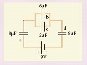
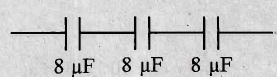
Cp = Cb + Cc
\(C_{P}=6+2=8 \mu \mathrm{F} \)
\(\frac{1}{C_{s}}=\frac{1}{C_a}+\frac{1}{C_p}=\frac{1}{C_d} \)
\(C_{s}=\frac{1}{8}+\frac{1}{8}+\frac{1}{8}=\frac{3}{8} \)
\(\therefore C_{s}=\frac{8}{3} \mu \mathrm{F} \)
Total capacitance \(C_{s}=\frac{8}{3} \times 10^{-6} \mathrm{~F} \)
Total Charge, \(Q=C_{s} V=\frac{8}{3} \times 10^{-6} \times 9 \)
\(Q_{a}=24 \mu C\)
(a) Charge on capacity \(Q_{a}=24 \mu C\) .....(1)
Charge on capacitor \(Q_{b}=24 \times \frac{6}{8}=18 \mu \mathrm{C} \) ..............(2)
Charge on capacitor \(Q_{c}=24 \times \frac{2}{8}=6 \mu \mathrm{C} \) ..............(3)
Charge on capacitor \(Q_{d}=24 \times \frac{8}{8}=24 \mu \mathrm{C} \) ..............(4)
(b) Potential difference across \(C_{a} \ is\ V_{a}=\frac{Q_{a}}{C_{a}} \)
\(=\frac{24}{8}=3 \mathrm{~V} \) ...(5)
Potential difference across \(C_{b}\ is \ V_{b}=\frac{Q_{b}}{C_{b}} \)
\(=\frac{18}{6}=3 \mathbf{V}\) ........(6)
Potential difference across \(C_{c}\ is \ V_{c}=\frac{Q_{c}}{C_{c}}=\frac{6}{2}=3 \mathrm{~V} \) ......(7)
Potential difference across \(C_{d}\ is \ V_{d}=\frac{Q_{d}}{C_{d}} \)
\(=\frac{24}{8}=3 \mathbf{V} \) ....(8)
(c) Energy stored in each capacitor \(U=\frac{1}{2} C V^{2}\)
Energy stored in \(\mathrm{C}_{\mathrm{a}} \text { is } U_{a}=\frac{1}{2} C_{a} V_{a}^{2}\)
\(U_{\mathrm{a}}=\frac{1}{2} \times 8 \times 10^{-6} \times 3 \times 3=36 \mu \mathrm{J}\) ....(9)
Energy stored in \(C_{b}\ is \ U_{b}=\frac{1}{2} C_{b} V_{b}^{2} \)
\(U=\frac{1}{2} \times 6 \times 10^{-6} \times 3 \times 3 \)
\(=27 \mu \mathrm{J} \) ........(10)
Energy stored in Ce is \(U_{c} =\frac{1}{2} C_{c} V_{c}^{2} \)
\(=\frac{1}{2} \times 2 \times 10^{-6} \times 3 \times 3=9 \mu \mathrm{J} \) ......(11)
Energy stored in Cd is \(U_{d} =\frac{1}{2} C_{d} V_{d}^{2} \)
\(U_d=\frac{1}{2} \times 8 \times 10^{-6} \times 3 \times 3 \)
\(=36 \times 10^{-6} \mathrm{~J}=36 \mu \mathrm{J} \) .........(12)
8.
(a) Electric Field E = \(\frac{Potential \ difference}{Distance}=\frac{V}{d}\)
Electric field E = 3 x 10⁶ Vm-1
Distance d = 1000 m
∴ Potential difference V = E x d =3 x 106 x 103 = 3 x 10⁹ V
(b) Potential Energy U = qV
U = 25 x 3 x 109 = 75 x 109 J
∴ Potential energy transferred to the ground = 75 x 109 J
9.
When an irregular shaped conductor is given positive charge, the electric field near the sharp end is very high and it ionizes the surrounding air. The positive ions are repelled at the sharp edge and negative ions are attracted towards the sharper edge. This reduces the total charge of the conductor near the sharp edge. This is called corona discharge.
10.
The capacitance C of a capacitor is defined as the ratio of the magnitude of charge on either of the conductor plates to the potential difference existing between the conductors. \(C=\frac{Q}{V}\)
Its unit is Coulomb per volt or farad (F).
11.
i) When the external electric field applied to the dielectric is very large, the bound charges (electrons) become free charges. This is called dielectric breakdown.
ii) The maximum electric field the dielectric can withstand before it breaksdown is called dielectric strength.
12.
The alignment of the dipole moments of the permanent or induced dipoles in the direction of applied electric field is called polarisation.
13.
Electrostatic shielding is the process of isolating a certain region of space from external field. It is based on the fact that electric field inside a conductor is zero. This property is called elecrostatic shielding because anything placed inside the cavity of the conductor will be completely shielded from external fields.
14.
h = 1 x 10⁻³ m, e = 1.6 x 10⁻¹⁹ C, me = 9.1 x 10⁻³¹ kg, mp =1.6 x 10⁻²⁷ kg
(a) (i) Time of flight for electron \(t_{c}=\sqrt{\frac{2 h m_{e}}{e E}}\)
Where,
\(E =\frac{V}{d}=\frac{5}{1 \times 10^{-3}}=5000 \mathrm{Vm}^{-1} \)
\(t_{e} =\sqrt{\frac{2 \times 1 \times 10^{-3} \times 9.1 \times 10^{-31}}{1.6 \times 10^{-19} \times 5000}}=\sqrt{\frac{18.2 \times 10^{-34}}{8 \times 10^{-16}}}=\sqrt{2.275 \times 10^{-18}} \)
= 1.5 x 10⁻⁹s
te = 1.5 ns (ignoring the gravity)
(ii) Time of flight for proton \(t_{p}=\sqrt{\frac{2 h m_{p}}{e E}}\)
\(t_{p} =\sqrt{\frac{2 \times 1 \times 10^{-3} \times 1.6 \times 10^{-27}}{1.6 \times 10^{-19} \times 5000}} \)
\(=\sqrt{\frac{3.2 \times 10^{-30}}{8 \times 10^{-16}}}=\sqrt{\frac{3.2}{8} \times 10^{-14}}=\sqrt{4000 \times 10^{-18}} \)
tp = 63 x 10-9s
tp = 63 ns (ignoring the gravity)
(b) Time of flight for neutron, \(t_{n}=\sqrt{\frac{2 h}{g}}\)
\(t_{n} =\sqrt{\frac{2 \times 1 \times 10^{-3}}{10}}=\sqrt{2 \times 10^{-4}} \)
\(=1,414 \times 10^{-2} \)
\(=14.14 \times 10^{-3} \mathrm{~s} \)
tn = 14.14 ms
(c) The value of Time period for electron is the least. So, electron will reach the bottom first.
15.
Energy stored in the capacitor
i) Capacitor not only stores the charge but also it stores energy. When a battery is connected to the capacitor, electrons of total charge - Q are transferred from one plate to the other plate. To transfer the charge, work is done by the battery. This work done is stored as electrostatic potential energy in the capacitor.
ii) To transfer an infinitesimal charge dQ for a potential difference V, the work done is given by
dW = V dQ
Where \(V=\frac { Q }{ C } \) .....(1)
iii) The total work done to charge a capacitor is
\(W=\int _{ 0 }^{ Q }{ \frac { Q }{ C } } dQ=\frac { { Q }^{ 2 } }{ 2C } \quad \quad ....(2)\)
This work done is stored as electrostatic potential energy (UE) in the capacitor.
\({ U }_{ E }=\frac { { Q }^{ 2 } }{ 2C } =\frac { 1 }{ 2 } { CV }^{ 2 },\quad (\therefore Q=CV)\quad ....(3)\)
(iv) This stored energy is thus directly proportional to the capacitance of the capacitor and the square of the voltage between the plates of the capacitor.Substituting \(C=\frac { { \varepsilon }_{ 0 }A }{ d } \) and V = Ed.
\(U=\frac { 1 }{ 2 } \left( \frac { { \varepsilon }_{ 0 }A }{ d } \right) { (Ed) }^{ 2 }=\frac { 1 }{ 2 } { \varepsilon }_{ 0 }(Ad){ E }^{ 2 }\quad \quad \quad \quad \quad ...(4)\)
where Ad = volume of the space between the capacitor plates. The energy stored per unit volume of space is defined as energy density \({ u }_{ E }=\frac { U }{ Volume } \)
Equation (4) ⇒ \({ u }_{ E }=\frac{1}{2}{ \varepsilon }_{ 0 }{ E }^{ 2 }\).....(5)
(v) From equation (5),
(a) We infer that the energy is stored in the electric field existing between the plates of the capacitor. Once the capacitor is allowed to discharge, the energy is retrieved.
(b) The energy density depends only on the electric field and not on the size of the plates of the capacitor.
(c) This is true for the electric field due to any type of charge configuration.
16.
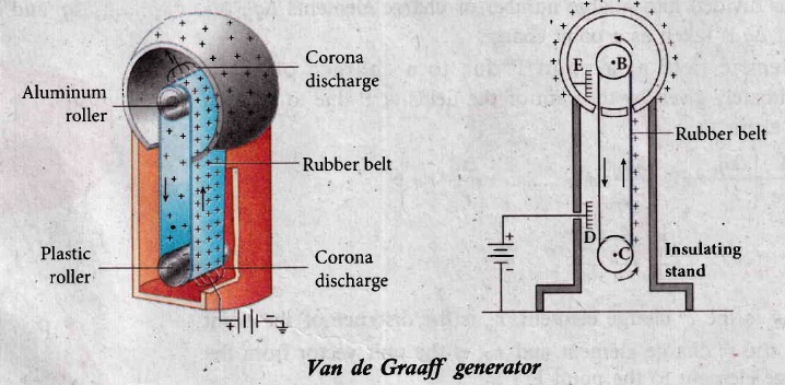
In the year 1929, Robert Van de Graaff designed a machine which produces a large amount of electrostatic potential difference, up to several million volts (107 V).
Principle:
Electrostatic induction and Action at points.
Construction:
(i) A large hollow spherical conductor is fixed on the insulating stand as shown in Figure. A pulley B is mounted at the center of the hollow sphere and another pulley C is fixed at the bottom. A belt made up of insulating materials like silk or rubber runs over both pulleys. The pulley C is driven continuously by the electric motor. Two comb-shaped metallic conductors E and D are fixed near the pulleys.
(ii) The comb D is maintained at a positive potential of 104 V by a power supply. The upper comb E is connected to the inner side of the hollow metal sphere
Working:
(i) Because of the high electric field near comb D, air between the belt and comb D gets ionized. The positive charges are pushed towards the belt and negative charges are attracted towards the comb D.
(ii) The positive charges stick to the belt and move up. When the positive charges reach the comb E, a large amount of negative and positive charges are induced on either side of comb E due to electrostatic induction.
(iii) As a result, the positive charges are pushed away from the comb E and they reach the outer surface of the sphere. Since the sphere is a conductor, the positive charges are distributed uniformly. on the outer surface of the hollow sphere.
(iv) At the same time the negative charges nullify the positive Charges in the belt due to corona discharge before it passes over the pulley.
(v) When the belt descends, it has almost no net charge. At the bottom, it again gains a large positive charge. The belt goes up and delivers the positive charges to the outer surface of the sphere.
(vi) This process continues until the outer surface produces the potential difference of the order of 107 which is the limiting value. We cannot store charges beyond this limit since the extra charge starts leaking to the surroundings due to ionization of air. The leakage of charges can be reduced by enclosing the machine in a gas filled steel chamber at very high pressure.
(vii) The high voltage produced in this Van de Graaff generator is used to accelerate positive ions (protons and deuterons) for nuclear disintegrations and other applications.
17.
Distribution of charges in a conductor:
(i) Consider two conducting spheres A and B of radii r1 and r2 respectively connected to each other by a thin conducting wire as shown in the Figure. The distance between the spheres is much greater than the radii of either spheres.
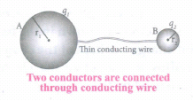
(ii) If a charge Q is introduced into any one of the spheres, this charge Q is redistributed into both the spheres such that the electrostatic potential is same in both the spheres. They are now uniformly charged and attain electrostatic equilibrium. Let q1 be the charge residing on the surface of sphere A and q2 is the charge residing on the surface of sphere B such that Q = q1 + q2, The charges are distributed only on the surface and there is no net charge inside the conductor.
The electrostatic potential at the surface of the sphere A is given by
\({ V }_{ A }=\frac { 1 }{ 4\pi { \varepsilon }_{ 0 } } \frac { { q }_{ 1 } }{ { r }_{ 1} } \quad \quad ...(1)\)
(iii) The electrostatic potential at the surface of the sphere B is given by ,
\({ V }_{ B }=\frac { 1 }{ 4\pi { \varepsilon }_{ 0 } } \frac { { q }_{ 2 } }{ { r }_{ 2 } } \) ...(2)
iv) The surface of the conductor is an equipotential. Since the spheres are connected by the conducting wire, the surfaces of both the spheres together form an equipotential surface.
This implies that
VA= VB
or \(\frac { { q }_{ 1 } }{ { r }_{ 1 } } =\frac { { q }_{ 2 } }{ { r }_{ 2 } } \) ...(3)
v) Let us take the charge density on the surface of sphere A and charge density on the surface of sphere B is σ2.This implies that q1 = 4πr12σ1 and 4πr22σ2 substituting these values into equation (3), we get
σ1r1 = σ2r2 ...(4)
from which we conclude that σr = constant ...(5)
Lightning conductor:
It is used to protect tall buildings from lightning strikes.
Principle:
(i) Action at points (or) corona discharge.
(ii) This device consists of a long thick copper rod passing from top of the building to the ground.
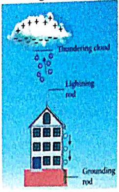
(iii) The upper end of the rod has a sharp spike or a sharp needle as shown in Figure.
(iv) The lower end of the rod is connected to copper plate which is buried deep into the ground.
(v) When a negatively charged cloud is passing above the building, it causes a positive charge on the spike. Since the induced charge density on thin sharp spike is large, it results in a corona discharge. This positive Charge ionizes the surrounding air which in turn neutralizes the negative charge in the cloud.
(vi) The negative charge pushed to the spikes passes through the copper rod and is safely diverted to the Earth. The lightning arrester does not stop the lightning; rather it diverts the lightning to the ground safely.
18.
(a) Capacitor in series
(i) Consider three capacitors of capacitance C1, C2 and C3 connected in series with a battery of voltage V as shown in the Figure (a).
(ii) As soon as the battery is connected to the capacitors in series, the electrons of charge -Q are transferred from negative terminal to the right plate of C3 which pushes the electrons of same amount -Q from left plate of C3 to the right plate of C2 due to electrostatic induction.
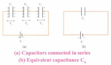
(iii) Similarly, the left plate of C2 pushes the charges of -Q to the right plate of C1 which induces the positive charge +Q on the left plate of C1.
(iv) At the same time, electrons of charge -Q are transferred from left plate of C1 to positive terminal of the battery.
(v) By these processes, each capacitor stores the same amount of charge Q.
(vi) The capacitances of the capacitors are in general different so that the voltage across each capacitor is also different and are denoted as V1, V2 and V3 respectively.
(vii) The sum voltage across capacitor must be equal to the voltage of the battery.
V = V1 + V2 + V3 ....(1)
Since, Q = CV
We have V = \(\frac { Q }{ { C }_{ 1 } } +\frac { Q }{ { C }_{ 2 } } +\frac { Q }{ { C }_{ 3 } } \)
\(=Q\left[ \frac { 1 }{ { C }_{ 1 } } +\frac { 1 }{ { C }_{ 2 } } +\frac { 1 }{ { C }_{ 3 } } \right] ...(2)\)
(viii) If three capacitors in series are considered to form an equivalent single capacitor Cs shown in Figure (b), then we have \(V=\frac { Q }{ { C }_{ s } } \). Substituting this expression into equation (2), we get
\(\frac { Q }{ { C }_{ s } } =Q\left( \frac { 1 }{ { C }_{ 1 } } +\frac { 1 }{ { C }_{ 2 } } +\frac { 1 }{ { C }_{ 3 } } \right) \)
\(\frac { 1 }{ { C }_{ s } } =\frac { 1 }{ { C }_{ 1 } } +\frac { 1 }{ { C }_{ 2 } } +\frac { 1 }{ { C }_{ 3 } } \) ...(3)
(ix) Thus, the inverse of the equivalent capacitance Cs of three capacitors connected in series is equal to the sum of the inverses of each capacitance. This equivalent capacitance Cs, is always less than the smallest individual capacitance in the series.
(b) Capacitor in parallel
i) Consider three capacitors of capacitance C1, C2 and C3 connected in parallel with a battery of voltage V as shown in Figure (a).
ii) Since corresponding sides of the capacitors are connected to the same positive and negative terminals of the battery, the voltage across each capacitor is equal to the battery's voltage.
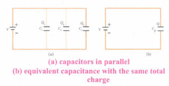
iii) Since capacitance of the capacitors is different, the charge stored in each capacitor is not the same. Let the charge stored in the three capacitors be Q1, Q2, and Q3 respectively.
iv) According to the law of conservation of total charge, the sum of these three charges is equal to the charge Q transferred by the battery,
Q = Q1 + Q2 + Q3 ...(4)
Now, since Q = CV, we have
Q = C1V + C2V + C3V ...(5)
(v) If these three capacitors are considered to form a single capacitance C, which stores the total charge Q as shown in the Figure (b), then we can write Q = CpV. Substituting this in equation (2), we get
CpV = C1V + C2V + C3V
Cp = C1+ C2 + C3 ...(6)
vi) Thus, the equivalent capacitance of capacitors connected in parallel is equal to the sum of the individual capacitances.
vii) The equivalent capacitance Cp, in a parallel connection is always greater than the largest individual capacitance. In a parallel connection, it is equivalent as area of each capacitance adds to give more effective area such that total capacitance increases.
19.
Effect of dielectrics in capacitors:
Suppose dielectrics like mica, glass or paper are introduced between the plates, then the capacitance of the capacitor is altered. The dielectric can be inserted into the plates in two different ways.
(i) when the capacitor is disconnected from the battery.
(ii) when the capacitor is connected to the battery.
(i) When the capacitor is disconnected from the battery
Consider a capacitor with two parallel plates each of cross-sectional area A and are separated by a distance d. The capacitor is charged by a battery of voltage Vo and the charge stored is Qo. The capacitance of the capacitor without the dielectric is,
\(C_{0}=\frac{Q_{0}}{V_{0}}\) ....(i)
The battery is then disconnected from the capacitor and the dielectric is inserted between the plates. This is shown in Figure.
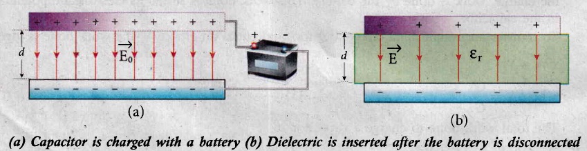
The introduction of dielectric between the plates will decrease the electric field. Experimentally it is found that the modified electric field is given by,
\(E=\frac{E_{0}}{\varepsilon_{r}}\) ....(2)
Here Eo is the electric field inside the capacitors when there is no dielectric and \(\varepsilon_{\mathrm{r}}\) is the relative permittivity of the dielectric or simply known as the dielectric constant. Since \(\varepsilon_{\mathrm{r}}\) > 1, the electric field E < Eo.
As a result, the electrostatic potential difference between the plates (V = Ed) is also reduced. But at the same time, the charge Qo will remain constant once the battery is disconnected.
Hence the new potential difference is
\(V=E d=\frac{E_{0}}{\varepsilon_{r}} d=\frac{V_{0}}{\varepsilon_{r}}\) .......(3)
We know that capacitance is inversely proportional to the potential difference. Therefore as V decreases, C increases.
Thus new capacitance in the presence of a dielectric is
\(C=\frac{Q_{0}}{V}=\varepsilon_{r} \frac{Q_{0}}{V_{0}}=\varepsilon_{r} C_{0}\) ......(4)
Since \(\varepsilon_{\mathrm{r}}\) > 1, we have C > Co. Thus insertion of the dielectric increases the capacitance.
We know that, Co =\(\frac{\varepsilon_{\mathrm{o}} A}{d}\) ...........(5)
Equation (4) ⇒ \(C=\frac{\varepsilon_{r} \varepsilon_{0} A}{d}=\frac{\varepsilon A}{d} \) ..........(6)
where \(\varepsilon=\varepsilon_{\mathrm{r}} \varepsilon_{\mathrm{o}}\) is the permittivity of the dielectric medium.
The energy stored in the capacitor before the insertion of a dielectric is given by,
\(U_{0}=\frac{1}{2} \frac{Q_{0}^{2}}{C_{0}}\) .......(7)
After the dielectric is inserted, the charge Qo remains constant but the capacitance is increased. As a result, the stored energy is decreased.
\(U=\frac{1}{2} \frac{Q_{0}^{2}}{C}=\frac{1}{2} \frac{Q_{0}^{2}}{\varepsilon_{r} C_{0}}=\frac{U_{0}}{\varepsilon_{r}}\) ..........(8)
Since \(\varepsilon_{\mathrm{r}}\) > 1we get U < Uo. There is a decrease in energy because, when the dielectric is inserted, the capacitor spends some energy in pulling the dielectric inside.
(ii) When the battery remains connected to the capacitor:
When the battery of voltage vo remains connected to the capacitor and the dielectric is inserted into the capacitor, then
(a) The potential difference vo across the plates remains constant.
(b) The charge stored in the capacitor is increased by a factor \(\varepsilon_{\mathrm{r}}\). (Experimentally found).
.jpg)
\({Q}=\varepsilon_{r} Q_{0}\) .......(1)
Due to this increased charge, the capacitance is also increased. The new capacitance is,
\(C=\frac{Q}{V_{0}}=\varepsilon_{r} \frac{Q_{0}}{V_{0}}=\varepsilon_{r} C_{0}\) ......(2)
However the reason for the increase in capacitance in this case where the battery remains connected is different from the case when the battery is disconnected before introducing the dielectric.
The energy stored in the capacitor before the insertion of a dielectric is given by,
\(U_{0}=\frac{1}{2} C_{0} V_{0}^{2}\) ....(4)
After the dielectric is inserted, the capacitance is increased; hence the stored energy is also increased.
\( U=\frac{1}{2} C V_{0}^{2}=\frac{1}{2} \varepsilon_{r} C_{0} V_{0}^{2}=\varepsilon_{r} U_{0} \) .....(5)
\(Since \ \varepsilon_{r}>1\ we \ have \ U>U_{o}.\)
Note: Here we have not used the expression \(U_o=\frac{1}{2}\frac{Q_0^2}{C_0}\)because here, both charge and capacitance are changed, whereas in equation (4), Vo remains constant.
Since voltage between the capacitor Vo is constant, the electric field between the plates also remains constant .The energy density is given by,
\(u=\frac{1}{2} \varepsilon E_{0}^{2}\) ..(6)
where ε is the permittivity of the given dielectric material.

12th Standard Syllabus & Materials
12th Standard
TN 12th Computer Applications களப்பெயர் முறைமை (DNS) Sample Question Papers Study Material - QB365 Set A
NEW12th Standard
TN 12th Computer Applications வலையமைப்பு எடுத்துக்காட்டுகள் மற்றும் நெறிமுறைகள் Sample Question Papers Study Material - QB365 Set A
NEW12th Standard
TN 12th Computer Applications கணினி வலையமைப்பு ஓர் அறிமுகம் Sample Question Papers Study Material - QB365 Set A
NEW12th Standard
TN 12th Computer Applications PHP-உடன் MySQL-ஐ இணைத்தல் Sample Question Papers Study Material - QB365 Set A



Tamilnadu Stateboard 12th Standard Subjects

Maths

Chemistry
Physics

Biology

Computer Science

Business Maths and Statistics

Economics

Commerce

Accountancy

History

Computer Applications
Biology
Computer Technology
Computer Applications
Computer Science
Business Maths and Statistics
Commerce
Economics
Maths
Chemistry
Physics
Computer Technology
History
Accountancy

Tamil

English

French
Tamilnadu Stateboard Standards

