
 100% FREE ACCESS
12th Standard Syllabus & Materials
12th Standard
TN 12th Maths Applications of Matrices and Determinants Sample Question Papers Study Material - QB365 Set A
NEW12th Standard
TN 12th Computer Applications மின்னணு தரவு பரிமாற்றம் Sample Question Papers Study Material - QB365 Set A
NEW12th Standard
TN 12th Computer Applications மின் - வணிக பாதுகாப்பு அமைப்புகள் Sample Question Papers Study Material - QB365 Set A
NEW12th Standard
TN 12th Computer Applications மின்னணு செலுத்தல் முறைகள் Sample Question Papers Study Material - QB365 Set A
NEW12th Standard
TN 12th Computer Applications மின் - வணிகம் Sample Question Papers Study Material - QB365 Set A
NEW12th Standard
TN 12th Computer Applications திறந்த மூல கருத்துருக்கள் Sample Question Papers Study Material - QB365 Set A

Published on: 28/11/2025
Download Tamil Nadu 12th Standard Physics question papers, model tests, one-mark questions, important questions, and public exam papers in PDF format. Free study materials and answer keys for TN State Board students.
Questions + Answers key
Take MCQ Physics Test
1.
Why does sky appear blue?
2.
State Biot-Savart’s law.
3.
State Fleming’s right hand rule.
4.
What are electromagnetic waves?
5.
Define ‘electric dipole’. Give the expression for the magnitiude of its electric dipole moment and the direction.
6.
Write a short note on superposition principle.
7.
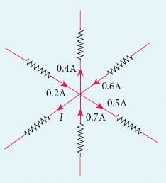
For the given circuit find the value of I.
8.
Distinguish between drift velocity and mobility.
9.
What are Fraunhofer lines? How are they useful in the identification of elements present in the Sun?
10.
List out the characteristics of photons.
11.
Give the applications photocell.
12.
Derive an expression for de Broglie wavelength of electrons.
13.
Mention the various energy losses in a transformer.
14.
Obtain the expression for capacitance for a parallel plate capacitor.
15.
In a Wheatstone’s bridge P = 100 Ω, Q = 1000 Ω and R = 40 Ω. If the galvanometer shows zero deflection, determine the value of S.
16.
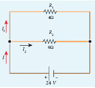
Calculate the equivalent resistance in the following circuit and also find the values of current I, I1 and I2 in the given circuit.
17.
An e.m. wave is propagating in a medium with a velocity \(\vec{v}=v \hat{i}\). The instantaneous oscillating electric field of this e.m. wave is along + y-axis, then the direction of oscillating magnetic field of the e.m. wave will be along _____.
–y direction
–x direction
+z direction
–z direction
18.
The potential energy of magnetic dipole whose dipole moment is \(\vec{p}_{m}=(-0.5 \hat{i}+0.4 \hat{j}) \mathrm{Am}^{2}\) kept in uniform magnetic field \(\vec{B}=0.2 \hat{i} \mathrm{~T}\).
–0.1 J
–0.8 J
0.1 J
0.8 J
19.
Stars twinkle due to, ______.
reflection
total internal reflection
refraction
polarisation
20.
An object is placed in front of a convex mirror of focal length off and the maximum and minimum distance of an object from the mirror such that the image formed is real and magnified.
2f and c
c and \(\infty\)
f and O
None of these
21.
A circular coil of radius 5 cm and 50 turns carries a current of 3 ampere. The magnetic dipole moment of the coil is nearly ____.
1.0 A m2
1.2 A m2
0.5 A m2
0.8 A m2
22.
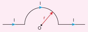
The magnetic field at the centre O of the following current loop is
\(\frac { { \mu }_{ ° }I }{ 4r } \bigotimes \)
\(\frac { { \mu }_{ ° }I }{ 4r } \bigodot \)
\(\frac { { \mu }_{ ° }I }{ 2r } \bigotimes \)
\(\frac { { \mu }_{ ° }I }{ 2r } \bigodot \)
23.
In an oscillating LC circuit, the maximum charge on the capacitor is Q. The charge on the capacitor when the energy is stored equally between the electric and magnetic fields is
\(\frac{Q}{2}\)
\(\frac{Q}{\sqrt3}\)
\(\frac{Q}{\sqrt2}\)
Q
24.
When the current changes from +2A to −2A in 0.05 s, an emf of 8 V is induced in a coil. The co-efficient of self-induction of the coil is
0.2H
0.4H
0.8H
0.1H
25.
Which of the following is NOT true for electromagnetic waves?
it transport energy
it transport momentum
it transport angular momentum
in vacuum, it travels with different speeds which depend on their frequency
26.
The electric and the magnetic fields, associated with an electromagnetic wave, propagating along negative X axis can be represented by _____.
\(\vec { E } ={ E }_{ 0 }\hat { i } \) and \(\vec { B } ={ B }_{ 0 }\hat { k } \)
\(\vec { E } ={ E }_{ 0 }\hat { k } \) and \(\vec { B } ={ B }_{ 0 }\hat { j } \)
\(\vec { E } ={ E }_{ 0 }\hat { i } \) and \(\vec { B } ={ B }_{ 0 }\hat { j } \)
\(\vec { E } ={ E }_{ 0 }\hat { j } \) and \(\vec { B } ={ B }_{ 0 }\hat { i } \)
27.
If the amplitude of the magnetic field is 3 x 10⁻⁶ T, then amplitude of the electric field for a electromagnetic waves is _____.
100 V m−1
300 V m-1
600 V m-1
900 V m-1
28.
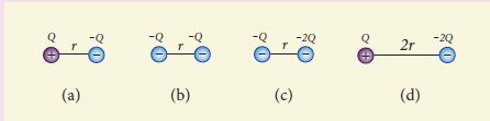
Rank the electrostatic potential energies for the given system of charges in increasing order
1 = 4 < 2 < 3
2 = 4 < 3 < 1
2 = 3 < 1 < 4
3 < 1 < 2 < 4
29.
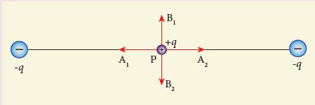
Two identical point charges of magnitude –q are fixed as shown in the figure below. A third charge +q is placed midway between the two charges at the point P. Suppose this charge +q is displaced a small distance from the point P in the directions indicated by the arrows, in which direction(s) will +q be stable with respect to the displacement?
A1 and A2
B1 and B2
both directions
No stable
30.
A carbon resistor of (47 ± 4.7 ) k Ω to be marked with rings of different colours for its identification. The colour code sequence will be ______.
Yellow – Green – Violet – Gold
Yellow – Violet – Orange – Silver
Violet – Yellow – Orange – Silver
Green – Orange – Violet - Gold
31.
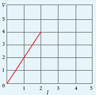
The following graph shows current versus voltage values of some unknown conductor. What is the resistance of this conductor?
2 ohm
4 ohm
8 ohm
1 ohm
32.
Obtain lens maker’s formula and mention its significance.
33.
Discuss the working of cyclotron in detail.
34.
Deduce the relation for the magnetic field at a point due to an infinitely long straight conductor carrying current using Biot-Savart law.
35.
Explain the construction and working of transformer.
36.
37.
Calculate the electric field due to a dipole on its axial line and equatorial plane.
38.
Obtain the condition for bridge balance in Wheatstone’s bridge.
1.
\(\mathrm{I} ∝ \frac{1}{\lambda^{4}}\)
According to Rayleigh's scattering equation, violet colour which has the shortest wavelength gets much scattered during day time. The next scattered colour is blue. As our eyes are more sensitive to blue colour than violet colour the sky appears blue during day time.
2.
Biot-Savart's law states that, the magnitude of magnetic field \(d\vec { B } \) at a point P at a distance of r from the small elemental length taken on a conductor carrying current varies
(i) directly as the strength of the current I
(ii) directly as the magnitude of the length of element \(\vec { dl } \)
(iii) directly as the sine of the angle θ between \(\vec { dl } \) and \(\hat { r } \).
(iv) inversely as the square of the distance r between the point P and length of element \(\vec { dl } \).
\(d\vec { B } =\frac { { \mu }_{ 0 } }{ 4\pi } \frac { I\vec { dl } \times \hat { r } }{ { r }^{ 2 } } \)
3.
The thumb, index finger and middle finger of right hand are stretched out in mutually perpendicular directions. If the index finger points the direction of the magnetic field and the thumb indicates the direction of motion of the conductor, then the middle finger will indicate the direction of the induced current.
4.
An electromagnetic waves are the waves that are radiated by an accelerated charge which propagates through space as coupled electric and magnetic fields, oscillating perpendicular to each other and to the direction of propagation of the wave.
5.
(i) Two equal and opposite charges separated by a small distance constitute an electric dipole.
(ii) The magnitude of the electric dipole moment is equal to the product of the magnitude of one of the charges and the distance between them, \(|\vec{p}|=2 q a\).
(iii) The electric dipole moment vector lies along the line joining two charges and is directed from -q to +q.
6.
It there are more than two charges, the total force acting on a given charge is equal to the vector sum of forces exerted on it by all the other charges.
Consider a system of n charges namely q1, q2, q3 ...qn. The force on q1 exerted by the charge q2 is \(\overrightarrow{F_{12}}=k \frac{q_{1} q_{2}}{r_{21}^{2}} \hat{r}_{21}\) .
The force on q1 exerted by the charge q3 is \(\overrightarrow{F_{13}}=k \frac{q_{1} q_{3}}{r_{31}^{2}} \hat{r}_{31}\)
By continuing this, the total force acting on the charge q1 due to all other charges is given by
\( \vec{F}_{1}^{\text { tot }}=\overrightarrow{F_{12}}+\overrightarrow{F_{13}}+\overrightarrow{F_{14}}+\ldots+\vec{F}_{1 n} \)
\(\vec{F}_{1} ^{\text { tot }}=k\left\{\frac{q_{1} q_{2}}{r_{21}^{2}} \hat{r}_{21}+\frac{q_{1} q_{3}}{r_{31}^{2}} \hat{r}_{31}+\frac{q_{1} q_{4}}{r_{41}^{2}} \hat{r}_{41}+\ldots+\frac{q_{1} q_{n}}{r_{n 1}^{2}} \hat{r}_{n 1}\right\}\)
7.
Applying Kirchoff’s rule to the point P in the circuit,
The arrows pointing towards P are positive and away from P are negative.
Therefore, 0.2A - 0.4A + 0.6A - 0.5A + 0.7A - I = 0
0.7 A - I = 0
1.5A - 0.9A – I = 0
0.6A - I = 0
I = 0.6 A
8.
| S.No | Drift velocity | Mobility |
| (i) | Drift velocity is the average velocity acquired by the electrons inside the conductor when it is subjected to an electric field. | Mobility is defined as the magnitude of the drift velocity per unit electric field. |
| (ii) | Vd = a\(\tau\) (or) Vd = μE. | μ =e\(\tau\)/m (or) u = vd/E. |
| (iii) | Its unit is m / s. | Its unit is m2/ Vs. |
9.
(i) When the spectrum obtained from the Sun is examined, it consists of large number of dark lines . These dark lines in the solar spectrum are called Fraunhofer lines.
(ii) The Absorption spectra for various materials are compared with the Fraunhofer lines in the solar spectrum, which helps in identifying elements present in the Sun's atmosphere.
10.
(i) The photons of light of frequency (v) and wavelength (λ) will have energy, given by
\(E=h v=\frac{h c}{\lambda}\)
(ii) The energy of a photon is determined by the frequency of the radiation and not by its intensity and the intensity has no relation with the energy of the individual photons in the beam.
(iii) The photons travel with the velocity of light and its momentum is given by
\(p=\frac{h}{\lambda}=\frac{h v}{c}\)
(iv) Since photons are electrically neutral, they are unaffected by electric and magnetic fields.
(v) When a photon interacts with matter (photon-electron collision), the total energy, total linear momentum, and angular momentum are conserved. Since photons may be absorbed (or) a new photon may be produced in such interactions, the number of photons may not be conserved.
11.
(i) Photo cells are used as switches and sensors.
(ii) Automatic switch on and off of street lights.
(iii) They are used for reproduction of sound in motion pictures
(iv) They are used as timers to measure the speed of athletes during a race.
(v) In photography, they are used to measure the intensity of the given light and to calculate the exact time of exposure.
12.
(i) An electron of mass m is accelerated through a potential difference of V volt. The kinetic energy acquired by the electron is given by
\(\cfrac { 1 }{ 2 } { mv }^{ 2 }=ev\)
(ii) Therefore, the speed v of the electron is
\(v=\sqrt { \cfrac { 2ev }{ m } } \)
Hence, the de Broglie wavelength of the matter waves associated with electron is
\(\lambda =\cfrac { h }{ mv } =\cfrac { h }{ \sqrt { 2mev } } \)
(iii) Substituting the known values in the above equation, we get
\(\lambda =\cfrac { 6.26\times { 10 }^{ -34 } }{ \sqrt { 2V\times 1.6\times { 10 }^{ -19 }\times 9.11\times { 10 }^{ -31 } } } \)
= \(\cfrac { 12.27\times { 10 }^{ -10 } }{ \sqrt { V } } m\)
\(\lambda =\cfrac { 12.27 }{ \sqrt { V } } \overset { o }{ A } \)
(iv) Since the kinetic energy of the electron, K = eV, then the de Broglie wavelength associated with electron can be also written as
\(\lambda =\cfrac { h }{ \sqrt { 2mK } } \)
13.
| S.No | Name of the losses | Source of losses | Method to minimise |
| (i) | (a) Core loss (or) Iron loss (or) Hysteresis loss | Transformer core is magnetised and demagnetised repeatedly |
Using steel of high silicon content in making transformer core |
| (b) Eddy current loss | Alternating magnetic flux in the core induces eddy currents in it. |
Using very thin laminations of transformer core. | |
| (ii) | Copper loss | When the electric current flows through windings of transformers, some amount of energy is dissipated due to Joule heating |
Using wires of larger diameter |
| (iii) | Flux leakage | The magnetic lines of primary coil are not completely linked with secondary coil. |
Windings the coils one over the other. |
14.
Capacitance of a parallel plate capacitor:
(i) Consider a capacitor with two parallel plates each of cross-sectional area A and separated by a distance d as shown in Figure.
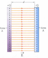
(ii) The electric field between two infinite parallel plates is uniform and is given by \(E=\frac { \sigma }{ { \varepsilon }_{ o} } \) where σ is the surface charge density on the plates \(\left( \sigma =\frac { Q }{ A } \right) \).
iii) If the separation distance d is very much smaller than the size of the plate (d2 < < A), then the above result is used even for finite-sized parallel plate capacitor.
The electric field between the plates is
\(E=\frac { Q }{ A{ \varepsilon }_{ 0 } } ...(1)\)
iv) Since the electric field is uniform, the electric potential between the plates having separation d is given by
\(V=Ed=\frac { Qd }{ A{ \varepsilon }_{ 0 } } \quad \quad \quad ...(2)\)
Therefore the capacitance of the capacitor is given by
\(C=\frac { Q }{ V } =\frac { Q }{ \left( \frac { Qd }{ A{ \varepsilon }_{ 0 } } \right) } =\frac { { \varepsilon }_{ 0 }A }{ d } \quad \quad ....(3)\)
(v) From equation (3), it is evident that capacitance is directly proportional to the area of cross section and is inversely proportional to the distance between the plates.
15.
\(\frac { P }{ Q } =\frac { R }{ S } \)
\(S=\frac { Q }{ P } \times R\)
\(S=\frac { 1000 }{ 100 } \times 40S=400\Omega \)
16.
Since the resistances are connected in parallel, therefore, the equivalent resistance in the circuit is
\(\frac { 1 }{ { R }_{ p } } =\frac { 1 }{ { R }_{ 1 } } +\frac { 1 }{ { R }_{ 2 } } =\frac { 1 }{ 4 } +\frac { 1 }{ 6 } \)
\(\frac { 1 }{ { R }_{ p } } =\frac { 5 }{ 12 } \Omega \quad or\quad { R }_{ p }=\frac { 12 }{ 5 } \Omega \)
The resistors are connected in parallel, the potential difference (voltage) across them is the same.
\({ I }_{ 1 }=\frac { V }{ { R }_{ 1 } } =\frac { 24V }{ 4\Omega } =6A\)
\({ I }_{ 2 }=\frac { V }{ { R }_{ 2 } } =\frac { 24 }{ 6 } =4A\)
The current I is the sum of the currents in the two branches. Then,
I = I1 + I2 = 6 A + 4 A = 10 A
17.
(c)
+z direction
18.
U =\(\vec{p_m}.\vec {B}\)
U = -(0.5\(\hat{i}\) + 0.4\(\hat{j}\)).(0.2\(\hat{j}\))
U = 0.1 J
19.
(c)
refraction
20.
Convex Mirror is diverging in nature and for all positions of objects, convex mirror forms virtual and erect image.
21.
Dipole moment, \(\vec{p}_m=n\times I\times\vec{A}\)
\(\vec{p}_m\) = 50 x 3 x 3.14 x 25 x 10-4 ≈ 1.2 A m2
22.
Magnetic filed at the centre of a circular
loop, B = \(\frac{μ_oI}{2\pi R}\)
From the figure, R =\(\frac{2r}{\pi}\)
\(\therefore B'=\frac{μ_oI}{2\pi \times\frac{2r}{\pi}}=\frac{μ_oI}{4r}\)
\(B'=\frac { { \mu }_{ ° }I }{ 4r } \bigotimes \)
23.
\(Q_{midpoint}=\frac{Q}{\sqrt{1^2+1^2}}=\frac{Q}{\sqrt2}\)
24.
\(\text {emf } e=8 \mathrm{~V} \)
\(d I=I_1-I_0=2-(-2)=4 \mathrm{~A} \)
\(\text {dt }=0.05 \mathrm{~s} \)
\(L=\frac{-e}{d I / d t}=\frac{-8}{4 / 0.05} \)
\(=\frac{-8 \times 0.05}{4}=\frac{-0.40}{4} \)
=-0.1 H
-ve sign indicates that self-induced emf always opposes the current w.r.t. time.
25.
(d)
in vacuum, it travels with different speeds which depend on their frequency
26.
\( { E } ={ E }_{ 0 }\hat { k } \) and \({ B } ={ B }_{ 0 }\hat { j } \)
27.
Bo = 3 x 10⁻⁶T
Amplitude of electric field, Eo = Boc
Eo = 3 x 10-6 x 3 x 108 = 900V m -1
28.
\(U=\frac{1}{4\piε_0}\frac{q_1q_2}{r_{12}}\)
\(i) U=\frac{1}{4\piε_0}\frac{Q(-Q)}{r}=\frac{1}{4\piε_0}[\frac{-Q^2}{r}]\)
\(ii) U=\frac{1}{4\piε_0}\frac{(-Q)(-Q)}{r}=\frac{1}{4\piε_0}[\frac{Q^2}{r}]\)
\(iii) U=\frac{1}{4\piε_0}\frac{Q(2Q)}{r}=\frac{1}{4\piε_0}[\frac{2Q^2}{r}]\)
\(iv) U=\frac{1}{4\piε_0}\frac{Q(-2Q)}{2r}=\frac{1}{4\piε_0}[\frac{-Q^2}{r}]\)
From the values, 1 = 4 < 2 < 3
29.
The charge + q will be stable between B1 and B2 with respect to the displacement.
30.
Yellow - 4
Violet - 7
Orange - 103
Silver - Tolerance - 10%
31.
Resistance, \(R=\frac{V}{I}=\frac{4}{2}=2 \ ohm\)
32.
(i) Let us consider a thin lens made up of a medium of refractive index n2 is placed in a medium of refractive index n1. Let R1 and R2 be the radii of curvature of two spherical surfaces (1) and (2) respectively and P be the pole.
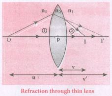
(ii) Consider a point object 'O' on the principal axis. A paraxial ray from 'O' which falls very close to P, after refraction at the surface (1) forms image at 1'.
(iii) Before it does so, it is again refracted by the surface (2). Therefore the final image is formed at I.
(iv) The general equation for the refraction at a single spherical surface is given from Equation,
\(\cfrac { { n }_{ 2 } }{ v } -\cfrac { { n }_{ 1 } }{ v} =\cfrac { \left( { n }_{ 2 }-{ n }_{ 1 } \right) }{ { R } } \)
For the refracting surface (1), the light goes from n1 to n2
\(\cfrac { { n }_{ 2 } }{ v' } -\cfrac { { n }_{ 1 } }{ u } =\cfrac { \left( { n }_{ 2 }-{ n }_{ 1 } \right) }{ { R }_{ 1 } } \) .....(1)
For the refracting surface (2), the light goes from n2 to n1
\(\frac{n_{1}}{v}+\frac{n_{2}}{v^{\prime}}=\frac{\left(n_{1}-n_{2}\right)}{R_{2}}\) ......(2)
For surface (2) I' acts as virtual object.
Adding the above two equations (1) and (2)
\(\cfrac { { n }_{ 1 } }{ v } -\cfrac { { n }_{ 1 } }{ u } =\left( { n }_{ 2 }-{ n }_{ 1 } \right) \left( \cfrac { 1 }{ { R }_{ 1 } } -\cfrac { 1 }{ { R }_{ 2 } } \right) \)
on further simplifying and rearranging,
\(\cfrac { 1 }{ v } -\cfrac { 1 }{ u } =\left( \cfrac { { n }_{ 2 }-{ n }_{ 1 } }{ { n }_{ 1 } } \right) \left( \cfrac { 1 }{ { R }_{ 1 } } -\cfrac { 1 }{ { R }_{ 2 } } \right) \)
\(\cfrac { 1 }{ v } -\cfrac { 1 }{ u } =\left( \cfrac { { n }_{ 2 } }{ n_{ 1 } } -1 \right) \left( \cfrac { 1 }{ { R }_{ 1 } } -\cfrac { 1 }{ { R }_{ 2 } } \right) \) ....(3)
If the object is at infinity, the image is formed at the focus of the lens. Thus, for u = \(\infty\), v = f. Then the equation becomes.
\(\cfrac { 1 }{ f } -\cfrac { 1 }{ \infty } =\left( \cfrac { { n }_{ 2 } }{ { { n }_{ 1 } } } -1 \right) \left( \cfrac { 1 }{ { R }_{ 1 } } -\cfrac { 1 }{ { R }_{ 2 } } \right) \)
\(\cfrac { 1 }{ f } =\left( \cfrac { { n }_{ 2 } }{ { n }_{ 1 } } -1 \right) \left( \cfrac { 1 }{ { R }_{ 1 } } -\cfrac { 1 }{ { R }_{ 2 } } \right) \) ......(4)
If the lens is kept in air, then we can take n2 = n and n1 = 1. So the equation (4) becomes,
\(\\ \cfrac { 1 }{ f } =\left( n-1 \right) \left( \cfrac { 1 }{ { R }_{ 1 } } -\cfrac { 1 }{ { R }_{ 2 } } \right) \) ..(5)
The above equation is called the lens maker's formula.
Significance:
It tells the lens manufacturers what curvature is needed to make a lens of desired focal length with a material of particular refractive index to make a lens of desired focal length. This formula holds good also for a concave lens.
33.
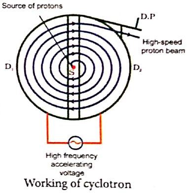
Cyclotron:
Device used to accelerate the charged particles to gain large kinetic energy.
Principle:
When a charged particle moves perpendicular to the magnetic field, it experiences magnetic Lorentz force.
Construction:
(i) The particles are allowed to move in between two semi-circular metal containers called Dees (hollow D - shaped objects).
(ii) The uniform magnetic field is controlled by an electromagnet. The direction of magnetic field is normal to the plane of the Dees.
(iii) Source is kept between two Dees.
(vi) Dees are connected to high frequency alternating potential difference.
Working:
(i) The ion ejected from source is positively charged.
(ii) It is accelerated towards negative potential Dees
(iii) This ion undergoes a circular path.
(iv) At this time, the polarities of the Dees are reversed, so that the ion is now accelerated towards Dee-2 with a greater velocity. For this circular motion, the centripetal force of the charged particle q is provided by Lorentz force.
\(\frac { m{ v }^{ 2 } }{ r } \) = qvB
⇒ r = \(\frac { m }{ qB } \)v ........(1)
⇒ r ∝ v
(v) If radius of the circular paths, increases, velocity also increases particles undergo spiral path with increasing radius.
(vi) When the frequency f at which the positive ion ciculates in the magnetic field must be equal to the constant frequency of the electrical oscillator fosc. This is called Resonance condition.
From equation, f = \(\frac { qB }{ 2\pi m } \) we have
fosc = \(\frac { qB }{ 2\pi m } \),
The time period of oscillation is
T = \(\frac { 2\pi m }{ qB } \)
The kinetic energy of the charged particle is,
KE = \(\frac { 1 }{ 2 } mv^{ 2 }=\frac { { q }^{ 2 }B^{ 2 }{ r }^{ 2 } }{ 2m } \) ........(2)
Limitations:
(i) The speed of ion is limited.
(ii) Electron cannot be accelerated.
(iii) Uncharged particles cannot be accelerated.
34.
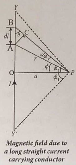
Let YY' be an infinitely long straight conductor carry current I. In order to calculate magnetic field at a point P which is at a distance a from the wire, let us consider a small line element dl (segment AB).
According to Biot Savart law, the magnetic field at a point P due to current element Idl is,
\({ d \vec B } =\frac { { \mu }_{ 0 } }{ 4\pi } \frac { { Idl sin \theta} }{ { r }^{ 2 } }\hat n \).
To apply trigonometry, draw a perpendicular AC to the line BP as shown in Figure.
In triangle ΔABC, \(\sin \theta=\frac{\mathrm{AC}}{\mathrm{AB}}\)
∴ AC = AB sinθ
\(\text { But, } A B =d l \Rightarrow A C=d l \sin \theta\)
Let dΦ be the angle subtended between AP and BP
ie., \(\angle \mathrm{APB}=\angle \mathrm{APC}=d \phi\)
In a triangle \(\triangle \mathrm{APC}, \sin (d \phi) \simeq A C / A P\)
Since, dΦ is very small, \(\sin (d \phi) \simeq d \phi\)
But, \(\mathrm{AP} =r \Rightarrow A C=r d \phi \)
\(\therefore \mathrm{AC} =d l \sin \theta=r d \phi \)
\(\therefore d \vec{B} =\frac{\mu_0}{4 \pi} \frac{I}{r^2}(r d \phi) \hat{n}=\frac{\mu_0}{4 \pi} \frac{I d \phi}{r} \hat{n}\)
Let Φ be the angle between AP and OP
\(\text {In a } \triangle \mathrm{OPA}, \cos \phi =\frac{\mathrm{OP}}{\mathrm{AP}}=\frac{\mathrm{a}}{\mathrm{r}} \)
\(r =\frac{a}{\cos \phi} \)
\(\text {Now, } d \vec{B} =\frac{\mu_0}{4 \pi} \frac{I}{a / \cos \phi} d \phi . \hat{n} \)
\(d \vec{B} =\frac{\mu_0 I}{4 \pi a} \cos \phi d \phi \hat{n}\)
The total magnetic field at P due to the conductor YY' is
\(\vec { B } = \int _{- \Phi _{ 1 } }^{ { \Phi }_{ 2} }d\vec B =\int _{ -\Phi _{ 1 } }^{ { \Phi }_{ 2 } }\frac { { \mu }_{ 0 }I }{ 4\pi a }{ cos\phi d\phi } \hat { n }\)
\(=\frac { { \mu }_{ 0 }I }{ 4\pi a }[{ sin\phi ]^{\phi_2} _{\phi_-1}} \hat { n }\)
\( \vec{B}=\frac { { \mu }_{ 0 }I }{ 4\pi a } (sin{ \Phi }_{ 1 }+sin{ \Phi }_{ 2 })\hat { n } \)
For infinitely long conductor, Φ1 = Φ2 = 90o
\(\therefore \vec{B}=\frac { { \mu }_{ 0 }I }{ 4\pi a } \times 2\hat{n}\Rightarrow\vec { B } =\frac { { \mu }_{ 0 }I }{ 2\pi a } \hat { n } \)
35.
Principle:
The principle of transformer is the mutual induction between two coils. That is, when an electric current passing through a coil changes with time, an emf is induced in the neighbouring coil.
Construction:
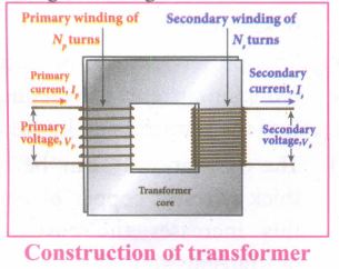
(i) In the simple construction of transformers, there are two coils of high mutual inductance wound over the same transformer core.
(ii) The core is generally laminated and is made up of a good magnetic material like silicon steel. Coils are electrically insulated but magnetically linked via transformer core.
(iii) The coil across which alternating voltage is applied is called primary coil P and the coil from which output power is drawn out is called secondary coil S. The assembled core and coils are kept in a container which is filled with suitable medium for better insulation and cooling purpose.
Working:
(i) If the primary coil is connected to a source of alternating voltage, an alternating magnetic flux is set up in the laminated core.
(ii) If there is no magnetic flux leakage, then whole of magnetic flux linked with primary coil is also linked with secondary coil.
(iii) This means that rate at which magnetic flux changes through each turn is same for both primary and secondary coils.
(iv) As a result of flux change, emf is induced in both primary and secondary coils. The emf induced in the primary coil vp or back of εp is given by,
vp = εp = -Np \(\frac{dФ_B}{dt}\) ........(1)
(vi) The frequency of alternating magnetic flux in the core is same as the frequency of the applied voltage. Therefore, induced emf in secondary will also have same frequency as that of applied voltage. The emf induced in the secondary coil εs is given by ,
εs = -Ns\(\frac{dФ_B}{dt}\)
Where Np and Ns are the number of turns in the primary and secondary coil respectively. If the secondary circuit is open, then εs = ሀs where u is the voltage ሀs across secondary coil
ሀs = εs = -Ns \(\frac{dФ_B}{dt}\) ........(2)
From equations (1) and (2),
\(\frac{v_s}{v_p}=\frac{N_s}{N_p}\) = K ........(3)
(vii) This constant K is known as voltage transformation ratio. For an ideal transformer, input power vpip= Output power vsis
where ip and is are the currents in the primary and secondary coil respectively.
(ix) Therefore,
\(\frac{V_s}{V_p}=\frac{N_s}{N_p}=\frac{I_p}{I_s}\) ........(4)
Equation (4) is written in terms of amplitude of corresponding quantities
\(\frac{V_s}{V_p}=\frac{N_s}{N_p}=\frac{I_p}{I_s}\) = K
i) If Ns> Np (or K > 1), ∴ Vs > Vp and Is < Ip This is the case of step-up transformer in which voltage is increased and the corresponding current is decreased.
ii) If Ns< Np (or K < 1), ∴ Vs < Vp and Is > Ip This is step-down transformer where voltage is decreased and the current is increased.
Efficiency of a transformer:
The efficiency η of a transformer is defined as the ratio of the useful output power to the input power. Thus,
\(η=\frac{Outpur \ power}{Input \ power}\times100% \) % ....(5)
36.
37.
Case (i): Electric field due to an electric dipole at points on the axial Iine:
Consider an electric dipole placed on the x-axis as shown in Figure. A point C is located at a distance of r from the midpoint O (of the dipole) along the axial line.
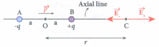
The electric field at a point C due to +q is
\({ \vec { E } }_{ + }=\frac { 1 }{ 4\pi { \varepsilon }_{ 0 } } \frac { q }{ { (r-a) }^{ 2 } } \) along BC
Since the electric dipole moment vector \(\vec { p } \) is from -q to +q and is directed along BC, the above equation is rewritten as
\({ \vec { E } }_{ + }=\frac { 1 }{ 4\pi { \varepsilon }_{ 0 } } \frac { q }{ { (r-a) }^{ 2 } } \hat { p } \) ....(1)
When \(\vec { p } \) is the electric dipole moment unit vector from -q to +q. The electric field at a point C due to -q is
\({ \vec { E } }_{ - }=-\frac { 1 }{ 4\pi { \varepsilon }_{ 0 } } \frac { q }{ { (r+a) }^{ 2 } } \hat { p } \) ....(2)
Since +q is located closer to the point C than -q, \({ \vec { E } }_{ + }\) is stronger than \({ \vec { E } }_{ - }\). Therefore, the length of the \({ \vec { E } }_{ + }\) vector is drawn larger than that of \({ \vec { E } }_{ - }\) vector.
The total electric field at point C is calculated using the superposition principle of the electric field.
\({ \vec { E } }_{ tot }={ \vec { E } }_{ + }+{ \vec { E } }_{ - }\)
\(=\frac { 1 }{ 4\pi { \varepsilon }_{ 0 } } \frac { q }{ { (r-a) }^{ 2 } } \hat { p } -\frac { 1 }{ 4\pi { \varepsilon }_{ 0 } } \frac { q }{ { (r+a) }^{ 2 } } \hat { p } \)
\({ \vec { E } }_{ tot }=\frac { q }{ 4\pi { \varepsilon }_{ 0 } } \left( \frac { 1 }{ { (r-a) }^{ 2 } } -\frac { 1 }{ { (r+a) }^{ 2 } } \right) \hat { p } \) ....(3)
\({ \vec { E } }_{ tot }=\frac { 1 }{ 4\pi { \varepsilon }_{ 0 } } q\left( \frac { 4ra }{( { r }^{ 2 }-{ a }^{ 2 })^2 } \right) \hat { p } \) ...(4)
Note that the total electric field is along \({ \vec { E } }_{ + }\), since +q is closer to C than -q.
If the point C is very far away from the dipole then (r >> a). Under this limit the term \(({ r }^{ 2 }-{ a }^{ 2 })\approx { r }^{ 2 }\).
Substituting this into equation (4), we get
\({ \vec { E } }_{ tot }=\frac { 1 }{ 4\pi { \varepsilon }_{ 0 } } \left( \frac { 4aq }{ { r }^{ 3 } } \right) \hat { p } (r>>a)\)
\(since\quad 2aq\hat { p } =\vec { p } \)
\({ \vec { E } }_{ tot }=\frac { 1 }{ 4\pi { \varepsilon }_{ 0 } } \frac { 2\vec { p } }{ { r }^{ 3 } } (r>>a)\) ...(5)
The direction \({ \vec { E } }_{ tot }\) is shown in Figure.
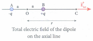
NOTE: If the point C is chosen on the left side of the dipole, the total electric field is still in the direction of \(\vec { p } \).
Case (ii) Electic field due to an electric dipole at a point on the equatorial plane:
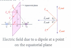
Consider a point C at a distance r from the midpoint O of the dipole on the equatorial plane. Since the point C is equidistant from +q and -q, the magnitude of the electric fields of +q and -q are the same. The direction of \({ \vec { E } }_{ + }\) is along BC and the direction of \({ \vec { E } }_{ - }\) is along CA. \({ \vec { E } }_{ + }\) and \({ \vec { E } }_{ - }\) are resolved into two components; one component parallel to the dipole axis and the other perpendicular to it. The perpendicular components \(|{ \vec { E } }_{ + }|\) sinθ and \(|{ \vec { E } }_{ -}|\) sinθ are equal in magnitude and oppositely directed and cancel each other. The magnitude of the total electric field at point C is the sum of the parallel components of \({ \vec { E } }_{ + }\) and \({ \vec { E } }_{ - }\) and its direction is along \(-\hat{p}\) as shown in the Figure.
\({ \vec { E } }_{ tot }=-|{ \vec { E } }_{ + }|cos\theta \hat { p } -|{ \vec { E } }_{ - }|cos\theta \hat { p } \) ...(6)
The magnitudes \({ \vec { E } }_{ + }\) and \({ \vec { E } }_{ - }\) are the same and given by,
\(|{ \vec { E } }_{ + }|=|{ \vec { E } }_{ - }|=\frac { 1 }{ 4\pi { \varepsilon }_{ 0 } } \frac { q }{ (r^2+a^2) } \) ...(7)
By substituting equation (7) into equation (6), we get
\({ \vec { E } }_{ tot }=\frac { 1 }{ 4\pi { \varepsilon }_{ 0 } } \frac { 2qcos\theta }{ ({ r }^{ 2 }+{ a }^{ 2 }) } \hat { p } ....(8)\)
\(=-\frac { 1 }{ 4\pi { \varepsilon }_{ 0 } } \frac { 2qa }{ ({ r }^{ 2 }+{ a }^{ 2 })^{ \frac { 3 }{ 2 } } } \hat { p } \)
Since \(cos \theta =\frac { a }{ \sqrt { { r }^{ 2 }+{ a }^{ 2 } } } \)
\({ \vec { E } }_{ tot }=\frac { 1 }{ 4\pi { \varepsilon }_{ 0 } } \frac { \vec { p } }{ ({ r }^{ 2 }+{ a }^{ 2 })^{ \frac { 3 }{ 2 } } } \)
Since \(\vec { p } \) = 2qa\(\hat { p } \) ...(9)
At very large distances (r >> a), the equation (9) becomes
\({ \vec { E } }_{ tot }=\frac { 1 }{ 4\pi { \varepsilon }_{ 0 } } \frac { \vec { p } }{ { r }^{ 3 } } (r>>a)\) ...(10)
Negative sign shows that direction of Electric field is opposite to the direction of dipole moment vector.
38.
Wheatstone's bridge:
i) An important application of Kirchhoff's rule is Wheatstone's bridge. It is used to compare Resistances and also helps in determining the unknown resistance in electrical network. The bridge consists of four resistances P, Q, R and S connected as shown in Figure.
ii) A galvanometer G is connected between the points B and D. The battery is connected between the points A and C. The current through the galvanometer is IG and its resistance is G.
Applying Kirchhoff's current rule to junction B
I1 - IG - I3 = 0 ..(1)
Applying Kirchhoff's current rule to junction D,
I2 + IG - I4 = 0 ...(2)
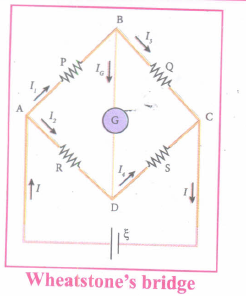
Applying Kirchhoff's voltage rule to loop ABDA,
I1P + IGG - I2R = 0 ...(3)
Applying Kirchhoff's voltage rule to loop ABCDA,
I1P + I3Q - I4S - I2R = 0 ...(4)
(iii) When the points B and D are at the same potential, the bridge is said to be balanced. As there is no potential difference between B and D, no current flows through galvanometer (IG = 0). Substituting IG = 0 in equation (1), (2) and (3), we get
I1 = I3 ..(5)
I2 = I4 ..(6)
I1P = I2R ..(7)
Substituting the equation (7) in equation (4),
I3Q = I4S .....(8)
Dividing equation (7) by equation (8), we get
\(\cfrac { P }{ Q } =\cfrac { R }{ S } \) .....(9)
(iv) This is the bridge balance condition. Only under this condition, galvanometer shows null deflection.

12th Standard Syllabus & Materials
12th Standard
TN 12th Computer Applications வலையமைப்பு வடமிடல் Sample Question Papers Study Material - QB365 Set A
NEW12th Standard
TN 12th Computer Applications களப்பெயர் முறைமை (DNS) Sample Question Papers Study Material - QB365 Set A
NEW12th Standard
TN 12th Computer Applications வலையமைப்பு எடுத்துக்காட்டுகள் மற்றும் நெறிமுறைகள் Sample Question Papers Study Material - QB365 Set A
NEW12th Standard
TN 12th Computer Applications கணினி வலையமைப்பு ஓர் அறிமுகம் Sample Question Papers Study Material - QB365 Set A



Tamilnadu Stateboard 12th Standard Subjects

Maths

Chemistry
Physics

Biology

Computer Science

Business Maths and Statistics

Economics

Commerce

Accountancy

History

Computer Applications
Biology
Computer Technology
Computer Applications
Computer Science
Business Maths and Statistics
Commerce
Economics
Maths
Chemistry
Physics
Computer Technology
History
Accountancy

Tamil

English

French
Tamilnadu Stateboard Standards


