
 100% FREE ACCESS
12th Standard Syllabus & Materials
12th Standard
TN 12th Maths Applications of Matrices and Determinants Sample Question Papers Study Material - QB365 Set A
NEW12th Standard
TN 12th Computer Applications மின்னணு தரவு பரிமாற்றம் Sample Question Papers Study Material - QB365 Set A
NEW12th Standard
TN 12th Computer Applications மின் - வணிக பாதுகாப்பு அமைப்புகள் Sample Question Papers Study Material - QB365 Set A
NEW12th Standard
TN 12th Computer Applications மின்னணு செலுத்தல் முறைகள் Sample Question Papers Study Material - QB365 Set A
NEW12th Standard
TN 12th Computer Applications மின் - வணிகம் Sample Question Papers Study Material - QB365 Set A
NEW12th Standard
TN 12th Computer Applications திறந்த மூல கருத்துருக்கள் Sample Question Papers Study Material - QB365 Set A

Published on: 28/11/2025
Download Tamil Nadu 12th Standard Physics question papers, model tests, one-mark questions, important questions, and public exam papers in PDF format. Free study materials and answer keys for TN State Board students.
Questions + Answers key
Take MCQ Physics Test
1.
Define work function of a metal. Give its unit.
2.
What is Rayleigh’s scattering?
3.
What are primary focus and secondary focus of a lens?
4.
5.
Define ‘capacitance’. Give its unit.
6.
Write a short note on superposition principle.
7.
Find the heat energy produced in a resistance of 10 Ω when 5 A current flows through it for 5 minutes.
8.
Define electrical resistivity.
9.
What are Fraunhofer lines? How are they useful in the identification of elements present in the Sun?
10.
Calculate the de Broglie wavelength of a proton whose kinetic energy is equal to 81.9 x 10⁻¹⁵ J. (Given: mass of proton is 1836 times that of electron).
11.
Derive an expression for de Broglie wavelength of electrons.
12.
Derive the relation between f and R for a spherical mirror.
13.
Mention the various energy losses in a transformer.
14.
Write short notes on
(a) microwaves
(b) X - rays
(c) Radio waves
(d) Visible spectrum
15.
Obtain the expression for capacitance for a parallel plate capacitor.
16.
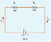
Calculate the equivalent resistance for the circuit which is connected to 24 V battery and also find the potential difference across each resistors in the circuit.
17.
A wire of length l carrying a current I along the Y direction is kept in a magnetic field is given by \(\vec { B } =\frac { \beta }{ \sqrt { 3 } } =(\hat { i } +\hat { j } +\hat { k } )T.\) The magnitude of Lorentz force acting on the wire is _____.
\(\sqrt { \frac { 2 }{ { 3 } } } \beta Il\)
\(\sqrt { \frac { 1 }{ { 3 } } } \beta Il\)
\(\sqrt { 2 } \beta Il\)
\(\sqrt { \frac { 1 }{ 2 } } \beta Il\)
18.
A thin insulated wire forms a plane spiral of N = 100 tight turns carrying a current I = 8 m A (milli ampere). The radii of inside and outside turns are a = 50 mm and b = 100 mm respectively. The magnetic induction at the centre of the spiral is ______.
\(5\mu T\)
\(7\mu T\)
\(8\mu T\)
\(10\mu T\)
19.
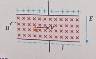
An electron moves in a straight line inside a charged parallel plate capacitor of uniform charge density σ. The time taken by the electron to cross the parallel plate capacitor undeflected when the plates of the capacitor are kept under constant magnetic field of induction \((\vec{B})\) is
\({ \varepsilon }_{ ° }\frac { elB }{ \sigma } \)
\({ \varepsilon }_{ ° }\frac { lB }{ \sigma {l} } \)
\({ \varepsilon }_{ ° }\frac { lB }{ {e}\sigma } \)
\({ \varepsilon }_{ ° }\frac { lB }{ \sigma } \)
20.
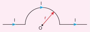
The magnetic field at the centre O of the following current loop is
\(\frac { { \mu }_{ ° }I }{ 4r } \bigotimes \)
\(\frac { { \mu }_{ ° }I }{ 4r } \bigodot \)
\(\frac { { \mu }_{ ° }I }{ 2r } \bigotimes \)
\(\frac { { \mu }_{ ° }I }{ 2r } \bigodot \)
21.
In an oscillating LC circuit, the maximum charge on the capacitor is Q. The charge on the capacitor when the energy is stored equally between the electric and magnetic fields is
\(\frac{Q}{2}\)
\(\frac{Q}{\sqrt3}\)
\(\frac{Q}{\sqrt2}\)
Q
22.
An inductor 20 mH, a capacitor 50 μF and a resistor 40Ω are connected in series across a source of emf V = 10 sin 340 t. The power loss in AC circuit is
0.76 W
0.89 W
0.46 W
0.67 W
23.
In an electrical circuit, R, L, C, and AC voltage source are all connected in series. When L is removed from the circuit, the phase difference between the voltage and current in the circuit is \(\frac{\pi}{3}\). Instead, if C is removed from the circuit, the phase difference is again \(\frac{\pi}{3}\). The power factor of the circuit is
1/2
1/\(\sqrt2\)
1
\(\sqrt3\)/2
24.
25.
A thin semi-circular conducting ring (PQR) of radius r is falling with its plane vertical in a horizontal magnetic field B, as shown in the figure.
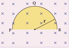
The potential difference developed across the ring when its speed v, is
Zero
\(\frac { { Bv\pi { r }^{ 2 } } }{ 2 } \) and P is at higher potential
πrBv and R is at higher potential
2rBv and R is at higher potential
26.
An electron moves on a straight line path XY as shown in the figure. The coil abcd is adjacent to the path of the electron. What will be the direction of current, if any, induced in the coil?
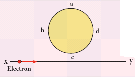
The current will reverse its direction as the electron goes past the coil
No current will be induced
abcd
adcb
27.
If voltage applied on a capacitor is increased from V to 2V, choose the correct conclusion.
Q remains the same, C is doubled
Q is doubled, C doubled
C remains same, Q doubled
Both Q and C remain same
28.
.JPG)
.JPG)
.JPG)
.JPG)
29.
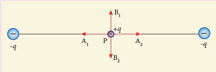
Two identical point charges of magnitude –q are fixed as shown in the figure below. A third charge +q is placed midway between the two charges at the point P. Suppose this charge +q is displaced a small distance from the point P in the directions indicated by the arrows, in which direction(s) will +q be stable with respect to the displacement?
A1 and A2
B1 and B2
both directions
No stable
30.
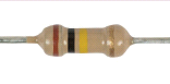
What is the value of resistance of the following resistor?
100 k Ω
10 k Ω
1 k Ω
1000 k Ω
31.
A toaster operating at 240 V has a resistance of 120 Ω. The power is ______.
400 W
2 W
480 W
240 W
32.
33.
Obtain Einstein’s photoelectric equation with necessary explanation.
34.
Obtain lens maker’s formula and mention its significance.
35.
Deduce the relation for the magnetic field at a point due to an infinitely long straight conductor carrying current using Biot-Savart law.
36.
Elaborate the standard construction details of AC generator.
37.
Write down Maxwell equations in integral form.
38.
Derive an expression for electrostatic potential due to an electric dipole.
39.
Obtain the condition for bridge balance in Wheatstone’s bridge.
1.
The minimum energy needed for an electron to escape from the metal surface is called work function of that metal.
Unit: electron volt (eV).
2.
If the scattering of light is by atoms and molecules which have size a yery less than that of the wavelength \({\lambda}\) of light a << \({\lambda}\) the scattering is called Rayleigh's scattering.
The intensity of Rayleigh's scattering is inversely proportional to fourth power of wavelength
\(\mathrm{I} ∝ \frac{1}{\lambda^{4}}\)
3.
Primary focus:
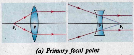
(i) The primary focus FI is defined as a point where an object should be placed to give parallel emergent rays to the principal axis after passing through lens.
Secondary focus:
.jpg)
(ii) The secondary focus F2 is defined as a point where all the parallel rays travelling close to the principal axis converge to form an image on the principal axis after passing through lens.
4.
5.
The capacitance C of a capacitor is defined as the ratio of the magnitude of charge on either of the conductor plates to the potential difference existing between the conductors. \(C=\frac{Q}{V}\)
Its unit is Coulomb per volt or farad (F).
6.
It there are more than two charges, the total force acting on a given charge is equal to the vector sum of forces exerted on it by all the other charges.
Consider a system of n charges namely q1, q2, q3 ...qn. The force on q1 exerted by the charge q2 is \(\overrightarrow{F_{12}}=k \frac{q_{1} q_{2}}{r_{21}^{2}} \hat{r}_{21}\) .
The force on q1 exerted by the charge q3 is \(\overrightarrow{F_{13}}=k \frac{q_{1} q_{3}}{r_{31}^{2}} \hat{r}_{31}\)
By continuing this, the total force acting on the charge q1 due to all other charges is given by
\( \vec{F}_{1}^{\text { tot }}=\overrightarrow{F_{12}}+\overrightarrow{F_{13}}+\overrightarrow{F_{14}}+\ldots+\vec{F}_{1 n} \)
\(\vec{F}_{1} ^{\text { tot }}=k\left\{\frac{q_{1} q_{2}}{r_{21}^{2}} \hat{r}_{21}+\frac{q_{1} q_{3}}{r_{31}^{2}} \hat{r}_{31}+\frac{q_{1} q_{4}}{r_{41}^{2}} \hat{r}_{41}+\ldots+\frac{q_{1} q_{n}}{r_{n 1}^{2}} \hat{r}_{n 1}\right\}\)
7.
R = 10 Ω, I = 5 A, t = 5 minutes = 5 x 60 s
H = I2 R t
= 52 x 10 x 5 x 60
= 25 x 10 x 300
= 25 x 3000
= 75000 J (or) 75 kJ
8.
Electrical resistivity of a material is defined as the resistance offered to current flow by a conductor of unit length having unit area of cross section.
9.
(i) When the spectrum obtained from the Sun is examined, it consists of large number of dark lines . These dark lines in the solar spectrum are called Fraunhofer lines.
(ii) The Absorption spectra for various materials are compared with the Fraunhofer lines in the solar spectrum, which helps in identifying elements present in the Sun's atmosphere.
10.
\(\text { K.E }=81.9 \times 10^{-15} \mathrm{~J} \)
\(\lambda =\frac{\mathrm{h}}{\sqrt{2 \mathrm{mk}}}=\frac{6.626 \times 10^{-34}}{\sqrt{2 \times 9.1 \times 10^{-3} \times 1836 \times 81.9 \times 10^{-15}}} \)
\(\lambda =\mathbf{4 . 0 0} \times 10^{-14} \mathrm{~m} \)
11.
(i) An electron of mass m is accelerated through a potential difference of V volt. The kinetic energy acquired by the electron is given by
\(\cfrac { 1 }{ 2 } { mv }^{ 2 }=ev\)
(ii) Therefore, the speed v of the electron is
\(v=\sqrt { \cfrac { 2ev }{ m } } \)
Hence, the de Broglie wavelength of the matter waves associated with electron is
\(\lambda =\cfrac { h }{ mv } =\cfrac { h }{ \sqrt { 2mev } } \)
(iii) Substituting the known values in the above equation, we get
\(\lambda =\cfrac { 6.26\times { 10 }^{ -34 } }{ \sqrt { 2V\times 1.6\times { 10 }^{ -19 }\times 9.11\times { 10 }^{ -31 } } } \)
= \(\cfrac { 12.27\times { 10 }^{ -10 } }{ \sqrt { V } } m\)
\(\lambda =\cfrac { 12.27 }{ \sqrt { V } } \overset { o }{ A } \)
(iv) Since the kinetic energy of the electron, K = eV, then the de Broglie wavelength associated with electron can be also written as
\(\lambda =\cfrac { h }{ \sqrt { 2mK } } \)
12.
Relation between f and R:
C ⇒ Center of curvature
F ⇒ Principal focus
i ⇒ Angle of incidence
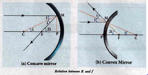
The angles
\(\tan i=\frac{P M}{P C} \text { and } \tan 2 i=\frac{P M}{P F}\)
As the angles are small, tan i = i and tan 2i = 2i.
\(\mathrm{i}=\frac{\mathrm{PM}}{\mathrm{PC}} \text { and } 2 \mathrm{i}=\frac{\mathrm{PM}}{\mathrm{PF}}\)
Simplifying further,
\(2 \frac{\mathrm{PM}}{\mathrm{PC}}=\frac{\mathrm{PM}}{\mathrm{PF}} ; 2 \mathrm{PF}=\mathrm{PC}, \mathrm{R}=2 \mathrm{f}\)
PF is focal length f and PC is the radius of curvature R.
R = 2f (or) f = R/2
13.
| S.No | Name of the losses | Source of losses | Method to minimise |
| (i) | (a) Core loss (or) Iron loss (or) Hysteresis loss | Transformer core is magnetised and demagnetised repeatedly |
Using steel of high silicon content in making transformer core |
| (b) Eddy current loss | Alternating magnetic flux in the core induces eddy currents in it. |
Using very thin laminations of transformer core. | |
| (ii) | Copper loss | When the electric current flows through windings of transformers, some amount of energy is dissipated due to Joule heating |
Using wires of larger diameter |
| (iii) | Flux leakage | The magnetic lines of primary coil are not completely linked with secondary coil. |
Windings the coils one over the other. |
14.
(a) Microwaves:
It is produced by special vacuum tubes such as klystron, magnetron and gunn diode. The frequency range of microwaves is 109 Hz to 1011 Hz. These waves undergo reflection and can be polarised.
Uses:
It is used in radar system for aircraft navigation, speed of the vehicle, microwave oven for cooking and very long distance wireless communication through satellites.
(b) X-rays:
lt is produced when there is sudden stopping of high speed electrons at high-atomic number target, and also by electronic transitions among the innermost orbits of atoms. The frequency range of X-rays is from 1017 Hz to 1019 Hz. X-rays have more penetrating power than ultraviolet radiation.
Uses:
X-rays are used extensively in studying structures of inner atomic electron shells and crystal structures. It is used in detecting fractures, diseased organs, formation of bones and stones, observing the progress of healing bones. Further, in a finished metal product, it is used to detect faults, cracks, flaws and holes.
(c) Radio waves:
It is produced by accelerated motion of charges in conducting wires. The frequency range is from few Hz to 109 Hz. It obeys reflection and diffraction.
Uses:
It is uses in radio and television communication systems and also in cellular phones to transmit voice communication in the ultra high frequency band.
(d) Visible light:
Visible light is produced by incandescent bodies and also it is radiated by excited atoms in gases. The frequency range is from 4 x 10¹⁴ Hz to 8 x 10¹⁴ Hz. It obeys the laws of interference, diffraction and can be polarised. It exhibits photo-electric effect also.
Uses:
It can be used to study the structure of molecules, arrangement of electrons in external shells of atoms and it causes sensation of vision.
15.
Capacitance of a parallel plate capacitor:
(i) Consider a capacitor with two parallel plates each of cross-sectional area A and separated by a distance d as shown in Figure.
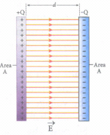
(ii) The electric field between two infinite parallel plates is uniform and is given by \(E=\frac { \sigma }{ { \varepsilon }_{ o} } \) where σ is the surface charge density on the plates \(\left( \sigma =\frac { Q }{ A } \right) \).
iii) If the separation distance d is very much smaller than the size of the plate (d2 < < A), then the above result is used even for finite-sized parallel plate capacitor.
The electric field between the plates is
\(E=\frac { Q }{ A{ \varepsilon }_{ 0 } } ...(1)\)
iv) Since the electric field is uniform, the electric potential between the plates having separation d is given by
\(V=Ed=\frac { Qd }{ A{ \varepsilon }_{ 0 } } \quad \quad \quad ...(2)\)
Therefore the capacitance of the capacitor is given by
\(C=\frac { Q }{ V } =\frac { Q }{ \left( \frac { Qd }{ A{ \varepsilon }_{ 0 } } \right) } =\frac { { \varepsilon }_{ 0 }A }{ d } \quad \quad ....(3)\)
(v) From equation (3), it is evident that capacitance is directly proportional to the area of cross section and is inversely proportional to the distance between the plates.
16.
Since the resistors are connected in series, the effective resistance in the circuit
= 4 Ω + 6 Ω = 10 Ω
The Current I in the circuit =\(\frac { V }{ { R }_{ eq } } =\frac { 24 }{ 10 } =2.4A\)
Voltage across 4Ω resistor
V1= IR1 = 2.4A x 4Ω = 9.6V
Voltage across 6 Ω resistor
V2 = IR2 = 2.4A x 6Ω = 14.4V
17.
\(\vec { B } =\frac { \beta }{ \sqrt { 3 } } =(\hat { i } +\hat { j } +\hat { k } )T\)
Using an equation,
Lorentz force, \(\vec{F}=Il\hat{j}\times\vec B\)
We can get,
Lorentz force \(F=\sqrt { \frac { 2 }{ { 3 } } } \beta Il\)
18.
(b)
\(7\mu T\)
19.
Electric field between the plates \(= \frac{σ}{ε_0}\)
Electric force on an electron \(= e\frac{σ}{ε_0}\)
Magnetic force on an electron, F = BIl
But, \(I= \frac{e}{t}\)
∵Electron moves in a straight line. So,
EF = MF
\(e\frac{σ}{ε_0}=B(\frac{e}{t})l\)
\(\therefore t = ε_0\frac{lB}{σ}\)
20.
Magnetic filed at the centre of a circular
loop, B = \(\frac{μ_oI}{2\pi R}\)
From the figure, R =\(\frac{2r}{\pi}\)
\(\therefore B'=\frac{μ_oI}{2\pi \times\frac{2r}{\pi}}=\frac{μ_oI}{4r}\)
\(B'=\frac { { \mu }_{ ° }I }{ 4r } \bigotimes \)
21.
\(Q_{midpoint}=\frac{Q}{\sqrt{1^2+1^2}}=\frac{Q}{\sqrt2}\)
22.
L = 20 x 10-3H. C = 50 x 10-6 F, R= 40Ω
enf V = 10 sin 340 t
\(\therefore V_0=10 \mathrm{~V}, \omega=340 \)
\(X_1=1 \omega^{\prime}=20 \times 10^3 \times 340 \)
\(=6800 \times 10^{-1}=6.8 \Omega \)
\(X_C=\frac{1}{C .} \)
\(=\frac{1}{50 \times 10^{-\alpha} \times 340}=\frac{10^{\circ}}{17000}=\frac{10^{\prime}}{17}=58.823 \Omega \)
\(Z=\sqrt{R^2+\left(X_6-X_1\right)^2} \)
\(=\sqrt{(40)^2+(58.82-6.8)^2} \)
\(=\sqrt{(40)^2+(52.02)^2} \)
\(=65.62 \Omega\)
The peak current in the circuit is,
\(I_0=\frac{V_0}{Z}=\frac{10}{65.62} \)
\(\cos 0=\frac{R}{Z}=\frac{40}{65.62} \)
\(\text{Power loss in A.C. circuit }=V_{r m} 1_{r \rightarrow \infty} \cos \phi \)
\(=\frac{1}{2} V_{\mathrm{o}} I_{\mathrm{c}} \cos \phi \)
\(=\frac{1}{2} \times 10 \times \frac{10}{65.62} \times \frac{40}{65.62}\)
\(\frac{2000}{4305.98}\)
= 0.46 W
23.
\(\Phi = \frac{\pi}{3}-\frac{\pi}{3}=0 \)
Power factor = cosФ = cos 0 = 1
24.
(a)
25.
(d)
2rBv and R is at higher potential
26.
The direction of conventional current is always opposite to the direction of flow of electrons.
27.
If voltage is increased from V to 2 V
Then Q1 = CV
Q2 = C(2 V) = 2 CV
∴ Q is doubled and C remains same
28.
(b)
29.
The charge + q will be stable between B1 and B2 with respect to the displacement.
30.
Brown - 1
Black - 0
Yellow - 104
(∴ R = 10 x 104 Ω = 100 kΩ)
31.
\(P=\frac{V^2}{R}=\frac{240 \times 240}{120}=480 \ W\)
32.
33.
(i) When a photon of energy hv is incident on a metal surface, it is completely absorbed by a single electron and the electron is ejected.
(ii) In this process, a part of the photon energy is used for the ejection of the electrons from the metal surface (photoelectric work function Φ0) and the remaining energy as the kinetic energy of the ejected electron. From the law of conservation of energy,
\(\\ \\ \\ hv=\phi { _{ 0 }+\cfrac { 1 }{ 2 } { mv }^{ 2 } }\) ......(1)
(iii) where m is the mass of the electron and v its velocity.
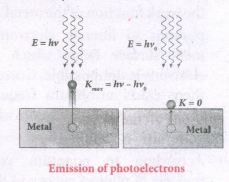
(iv) If we reduce the frequency of the incident light is reduced, the speed or kinetic energy of photo electrons is also reduced. At some frequency v0 of incident radiation, the photo electrons are ejected with almost zero kinetic energy.
Then the equation becomes.
\({ hv }_{ 0 }=\phi _{ 0 }\) ......(2)
(v) Where v0 is the threshold frequency. B rewriting the equation, we get
\(hv={ hv }_{ o }+\cfrac { 1 }{ 2 } { { mv }^{ 2 } }\) ......(3)
The equation is known as einstein's photoelectric equation.
(vi) If the electron does not lose energy by internal collisions, then it is emitted with maximum kinetic energy Kmax. Then
\({ K }_{ max }=\cfrac { 1 }{ 2 } { mv }^{ 2 }_{ max }\) ......(4)
(vii) where vmaxis the maximum velocity of max the electron ejected. The equation (1) is rearranged as follows:
\({ K }_{ max }=hv-{ \phi }_{ 0 }\)
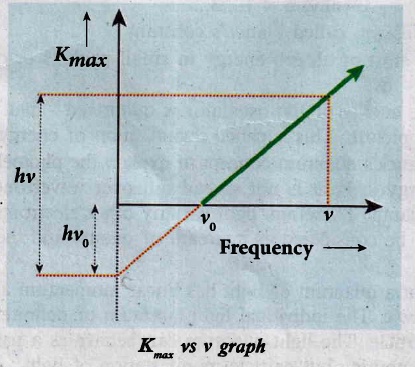
A graph between maximum kinetic energy Kmax of the photoelectron and frequency v of the incident light is a straight line.
34.
(i) Let us consider a thin lens made up of a medium of refractive index n2 is placed in a medium of refractive index n1. Let R1 and R2 be the radii of curvature of two spherical surfaces (1) and (2) respectively and P be the pole.
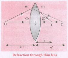
(ii) Consider a point object 'O' on the principal axis. A paraxial ray from 'O' which falls very close to P, after refraction at the surface (1) forms image at 1'.
(iii) Before it does so, it is again refracted by the surface (2). Therefore the final image is formed at I.
(iv) The general equation for the refraction at a single spherical surface is given from Equation,
\(\cfrac { { n }_{ 2 } }{ v } -\cfrac { { n }_{ 1 } }{ v} =\cfrac { \left( { n }_{ 2 }-{ n }_{ 1 } \right) }{ { R } } \)
For the refracting surface (1), the light goes from n1 to n2
\(\cfrac { { n }_{ 2 } }{ v' } -\cfrac { { n }_{ 1 } }{ u } =\cfrac { \left( { n }_{ 2 }-{ n }_{ 1 } \right) }{ { R }_{ 1 } } \) .....(1)
For the refracting surface (2), the light goes from n2 to n1
\(\frac{n_{1}}{v}+\frac{n_{2}}{v^{\prime}}=\frac{\left(n_{1}-n_{2}\right)}{R_{2}}\) ......(2)
For surface (2) I' acts as virtual object.
Adding the above two equations (1) and (2)
\(\cfrac { { n }_{ 1 } }{ v } -\cfrac { { n }_{ 1 } }{ u } =\left( { n }_{ 2 }-{ n }_{ 1 } \right) \left( \cfrac { 1 }{ { R }_{ 1 } } -\cfrac { 1 }{ { R }_{ 2 } } \right) \)
on further simplifying and rearranging,
\(\cfrac { 1 }{ v } -\cfrac { 1 }{ u } =\left( \cfrac { { n }_{ 2 }-{ n }_{ 1 } }{ { n }_{ 1 } } \right) \left( \cfrac { 1 }{ { R }_{ 1 } } -\cfrac { 1 }{ { R }_{ 2 } } \right) \)
\(\cfrac { 1 }{ v } -\cfrac { 1 }{ u } =\left( \cfrac { { n }_{ 2 } }{ n_{ 1 } } -1 \right) \left( \cfrac { 1 }{ { R }_{ 1 } } -\cfrac { 1 }{ { R }_{ 2 } } \right) \) ....(3)
If the object is at infinity, the image is formed at the focus of the lens. Thus, for u = \(\infty\), v = f. Then the equation becomes.
\(\cfrac { 1 }{ f } -\cfrac { 1 }{ \infty } =\left( \cfrac { { n }_{ 2 } }{ { { n }_{ 1 } } } -1 \right) \left( \cfrac { 1 }{ { R }_{ 1 } } -\cfrac { 1 }{ { R }_{ 2 } } \right) \)
\(\cfrac { 1 }{ f } =\left( \cfrac { { n }_{ 2 } }{ { n }_{ 1 } } -1 \right) \left( \cfrac { 1 }{ { R }_{ 1 } } -\cfrac { 1 }{ { R }_{ 2 } } \right) \) ......(4)
If the lens is kept in air, then we can take n2 = n and n1 = 1. So the equation (4) becomes,
\(\\ \cfrac { 1 }{ f } =\left( n-1 \right) \left( \cfrac { 1 }{ { R }_{ 1 } } -\cfrac { 1 }{ { R }_{ 2 } } \right) \) ..(5)
The above equation is called the lens maker's formula.
Significance:
It tells the lens manufacturers what curvature is needed to make a lens of desired focal length with a material of particular refractive index to make a lens of desired focal length. This formula holds good also for a concave lens.
35.
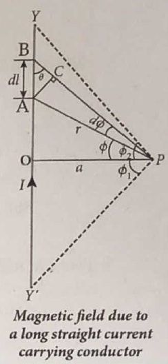
Let YY' be an infinitely long straight conductor carry current I. In order to calculate magnetic field at a point P which is at a distance a from the wire, let us consider a small line element dl (segment AB).
According to Biot Savart law, the magnetic field at a point P due to current element Idl is,
\({ d \vec B } =\frac { { \mu }_{ 0 } }{ 4\pi } \frac { { Idl sin \theta} }{ { r }^{ 2 } }\hat n \).
To apply trigonometry, draw a perpendicular AC to the line BP as shown in Figure.
In triangle ΔABC, \(\sin \theta=\frac{\mathrm{AC}}{\mathrm{AB}}\)
∴ AC = AB sinθ
\(\text { But, } A B =d l \Rightarrow A C=d l \sin \theta\)
Let dΦ be the angle subtended between AP and BP
ie., \(\angle \mathrm{APB}=\angle \mathrm{APC}=d \phi\)
In a triangle \(\triangle \mathrm{APC}, \sin (d \phi) \simeq A C / A P\)
Since, dΦ is very small, \(\sin (d \phi) \simeq d \phi\)
But, \(\mathrm{AP} =r \Rightarrow A C=r d \phi \)
\(\therefore \mathrm{AC} =d l \sin \theta=r d \phi \)
\(\therefore d \vec{B} =\frac{\mu_0}{4 \pi} \frac{I}{r^2}(r d \phi) \hat{n}=\frac{\mu_0}{4 \pi} \frac{I d \phi}{r} \hat{n}\)
Let Φ be the angle between AP and OP
\(\text {In a } \triangle \mathrm{OPA}, \cos \phi =\frac{\mathrm{OP}}{\mathrm{AP}}=\frac{\mathrm{a}}{\mathrm{r}} \)
\(r =\frac{a}{\cos \phi} \)
\(\text {Now, } d \vec{B} =\frac{\mu_0}{4 \pi} \frac{I}{a / \cos \phi} d \phi . \hat{n} \)
\(d \vec{B} =\frac{\mu_0 I}{4 \pi a} \cos \phi d \phi \hat{n}\)
The total magnetic field at P due to the conductor YY' is
\(\vec { B } = \int _{- \Phi _{ 1 } }^{ { \Phi }_{ 2} }d\vec B =\int _{ -\Phi _{ 1 } }^{ { \Phi }_{ 2 } }\frac { { \mu }_{ 0 }I }{ 4\pi a }{ cos\phi d\phi } \hat { n }\)
\(=\frac { { \mu }_{ 0 }I }{ 4\pi a }[{ sin\phi ]^{\phi_2} _{\phi_-1}} \hat { n }\)
\( \vec{B}=\frac { { \mu }_{ 0 }I }{ 4\pi a } (sin{ \Phi }_{ 1 }+sin{ \Phi }_{ 2 })\hat { n } \)
For infinitely long conductor, Φ1 = Φ2 = 90o
\(\therefore \vec{B}=\frac { { \mu }_{ 0 }I }{ 4\pi a } \times 2\hat{n}\Rightarrow\vec { B } =\frac { { \mu }_{ 0 }I }{ 2\pi a } \hat { n } \)
36.
Construction:
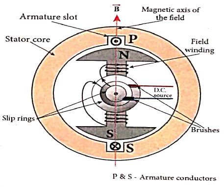
Alternator consists of two major parts, namely stator and rotor. As their names suggest, stator is stationary while rotor rotates inside the stator. In any standard construction of commercial alternators, the armature winding is mounted on stator and the field magnet on rotor.
The construction details of stator, rotor and various other components involved in them are given below.
(a) Stator:
The stationary part which has armature windings mounted in it is called stator. It has two components, namely stator frame, stator core and armature winding.
Stator core:
Stator core or armature core is made up of iron or steel alloy. It is a hollow cylinder and is laminated to minimize eddy current loss. The slots are cut on inner surface of the core to accommodate armature windings.
Armature winding:
Armature winding is the coil, wound on slots provided in the armature core.
(b) Rotor
Rotor contains magnetic field windings. The magnetic poles are magnetized by DC source. The ends of field windings are connected to a pair of slip rings, attached to a common shaft about which rotor rotates. Slip rings rotate along with rotor. To maintain connection between the DC source and field windings, two brushes are used which continuously slide over the slip rings.
37.
MaxWell's equations in integral form
i) Gauss law in electricity, \(\oint _s\vec{E} \vec{d} A=\frac{Q_{\text {enclosed }}}{\varepsilon_{o}}\)
ii) Gauss law in magnetism \(\oint _s \vec{B} \cdot \vec{d} A=0\)
iii) Faraday's law \(\oint_l \vec E. \vec {d l}=-\frac{d \phi _B}{d t}\)
iv) Ampere-Maxwell's law \(\oint_l \vec {B}. \vec {d l}=\mu_{o} i_c+\mu_{o} \varepsilon_{o} \frac{d}{d t} \oint_s \vec{E} \cdot {d} \vec A\)
38.
Electrostatic potential at a point due to an electric dipole :
(i) Consider two equal and opposite charges separated by a small distance 2a as shown in Figure. The point P is located at a distance r from the midpoint 'O' of the dipole. Let θ be the angle between the line OP and dipole axis AB.

(ii) Let r1 be the distance of point P from +q and r2 be the distance of point P from -q.
Potential at P due to charge +q\(=\frac { 1 }{ 4\pi { \varepsilon }_{ 0 } } \frac { q }{ { r }_{ 1 } } \)
Potential at P due to charge -q \(=-\frac { 1 }{ 4\pi { \varepsilon }_{ 0 } } \frac { q }{ { r }_{ 2 } } \)
Total potential at the point P,
\(V=\frac { 1 }{ 4\pi { \varepsilon }_{ 0 } } q\left( \frac { 1 }{ { r }_{ 1 } } -\frac { 1 }{ { r }_{ 2 } } \right) \) ....(1)
(iii) Suppose if the point P is far away from the dipole, such that (r >> a), then equation (1) can be expressed in terms of r.
By the cosine law for triangle BOP,
\({ r }_{ 1 }^{ 2 }={ r }^{ 2 }+{ a }^{ 2 }-2ra cos\theta \)
\({ r }_{ 1 }^{ 2 }={ r }^{ 2 }\left( 1+\frac { { a }^{ 2 } }{ { r }^{ 2 } } -\frac { 2a }{ r } cos\theta \right) \)
Since the point P is very far from dipole, then(r >> a). Then term \(\frac{a^{2}}{r^{2}}\)
\({ r }_{ 1 }^{ 2 }={ r }^{ 2 }\left( 1-2a\frac { cos\theta }{ r } \right) \)
\((or){ r }_{ 1 }=r{ \left( 1-\frac { 2a }{ r } cos\theta \right) }^{ \frac { 1 }{ 2 } }\)
\(\frac { 1 }{ { r }_{ 1 } } =\frac { 1 }{ r } { \left( 1-\frac { 2a }{ r } cos\theta \right) }^{ -\frac { 1 }{ 2 } }\)
iv) Since \(\frac{a}{r}\) << 1, we can use binomial theorem and retain the terms up to first order.
\(\frac { 1 }{ { r }_{ 1 } } =\frac { 1 }{ r } \left( 1+\frac { a }{ r } cos\theta \right) ...(2)\)
Similarly applying the cosine law for triangle AOP,
r22 = r2 + a2 - 2ra cos (180-θ)
Since cos(180 - θ) = - cos θ we get
r22= r2 + a2 + 2ra cos θ
Neglecting the term \(\frac { { a }^{ 2 } }{ { r }^{ 2 } } \) because (r >> a)
\({ r }_{ 2 }^{ 2 }={ r }^{ 2 }\left( 1+\frac { 2acos\theta }{ r } \right) \)
\({ r }_{ 2 }=r{ \left( 1+\frac { 2acos\theta }{ r } \right) }^{ \frac { 1 }{ 2 } }\)
Using Binomial theorem, we get
\(\frac { 1 }{ { r }_{ 2 } } =\frac { 1 }{ r } \left( 1-a\frac { cos\theta }{ r } \right) \quad \quad ...(3)\)
Substituting equation (3) and (2) in equation (1),
\(V=\frac { 1 }{ 4\pi { \varepsilon }_{ 0 } } q\left( \frac { 1 }{ r } \left( 1+a\frac { cos\theta }{ r } \right) -\frac { 1 }{ r } \left( 1-a\frac { cos\theta }{ r } \right) \right) \)
\(V=\frac { q }{ 4\pi { \varepsilon }_{ 0 } } \left( \frac { 1 }{ r } \left( 1+a\frac { cos\theta }{ r } -1+a\frac { cos\theta }{ r } \right) \right) \)
\(V=\frac { 1 }{ 4\pi { \varepsilon }_{ 0 } } \frac { 2aq }{ { r }^{ 2 } } cos\theta \)
v)
\(V=\frac { 1 }{ 4\pi { \varepsilon }_{ 0 } } \left( \frac { pcos\theta }{ { r }^{ 2 } } \right) \)
Now we can write p cos\(\theta =\vec { p } .\hat { r } \) where \(\hat { r } \) is the unit vector from the point O to point P. Hence the electric potential at a point P due to an electric dipole is given by
\(V=\frac { 1 }{ 4\pi { \varepsilon }_{ 0 } } \frac { \vec { p } .\hat { r } }{ { r }^{ 2 } } (r>>a)\quad ...(4)\)
Equation (4) is valid for distances very large compared to the size of the dipole. But for a point dipole, the equation (4) is valid for any distance.
Special cases:
Case (i) : If the point P lies on the axial line of the dipole on the side of +q, then θ = 0. Then the electric potential becomes
\(V=\frac { 1 }{ 4\pi { \varepsilon }_{ 0 } } \frac { p }{ { r }^{ 2 } } \quad \quad ...(5)\)
Case (ii) : If the point P lies on the axial line of the dipole on the side of -q, then θ = 180°, then
\(V=-\frac { 1 }{ 4\pi { \varepsilon }_{ 0 } } \frac { p }{ { r }^{ 2 } } \quad \quad ...(6)\)
Case (iii) : If the point P lies on the equatorial line of the dipole, then θ = 90°. Hence,
V = 0 .....(7)
39.
Wheatstone's bridge:
i) An important application of Kirchhoff's rule is Wheatstone's bridge. It is used to compare Resistances and also helps in determining the unknown resistance in electrical network. The bridge consists of four resistances P, Q, R and S connected as shown in Figure.
ii) A galvanometer G is connected between the points B and D. The battery is connected between the points A and C. The current through the galvanometer is IG and its resistance is G.
Applying Kirchhoff's current rule to junction B
I1 - IG - I3 = 0 ..(1)
Applying Kirchhoff's current rule to junction D,
I2 + IG - I4 = 0 ...(2)
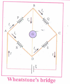
Applying Kirchhoff's voltage rule to loop ABDA,
I1P + IGG - I2R = 0 ...(3)
Applying Kirchhoff's voltage rule to loop ABCDA,
I1P + I3Q - I4S - I2R = 0 ...(4)
(iii) When the points B and D are at the same potential, the bridge is said to be balanced. As there is no potential difference between B and D, no current flows through galvanometer (IG = 0). Substituting IG = 0 in equation (1), (2) and (3), we get
I1 = I3 ..(5)
I2 = I4 ..(6)
I1P = I2R ..(7)
Substituting the equation (7) in equation (4),
I3Q = I4S .....(8)
Dividing equation (7) by equation (8), we get
\(\cfrac { P }{ Q } =\cfrac { R }{ S } \) .....(9)
(iv) This is the bridge balance condition. Only under this condition, galvanometer shows null deflection.

12th Standard Syllabus & Materials
12th Standard
TN 12th Computer Applications வலையமைப்பு வடமிடல் Sample Question Papers Study Material - QB365 Set A
NEW12th Standard
TN 12th Computer Applications களப்பெயர் முறைமை (DNS) Sample Question Papers Study Material - QB365 Set A
NEW12th Standard
TN 12th Computer Applications வலையமைப்பு எடுத்துக்காட்டுகள் மற்றும் நெறிமுறைகள் Sample Question Papers Study Material - QB365 Set A
NEW12th Standard
TN 12th Computer Applications கணினி வலையமைப்பு ஓர் அறிமுகம் Sample Question Papers Study Material - QB365 Set A



Tamilnadu Stateboard 12th Standard Subjects

Maths

Chemistry
Physics

Biology

Computer Science

Business Maths and Statistics

Economics

Commerce

Accountancy

History

Computer Applications
Biology
Computer Technology
Computer Applications
Computer Science
Business Maths and Statistics
Commerce
Economics
Maths
Chemistry
Physics
Computer Technology
History
Accountancy

Tamil

English

French
Tamilnadu Stateboard Standards


