
 100% FREE ACCESS
12th Standard Syllabus & Materials
12th Standard
TN 12th Computer Applications மின்னணு தரவு பரிமாற்றம் Sample Question Papers Study Material - QB365 Set A
NEW12th Standard
TN 12th Computer Applications மின் - வணிக பாதுகாப்பு அமைப்புகள் Sample Question Papers Study Material - QB365 Set A
NEW12th Standard
TN 12th Computer Applications மின்னணு செலுத்தல் முறைகள் Sample Question Papers Study Material - QB365 Set A
NEW12th Standard
TN 12th Computer Applications மின் - வணிகம் Sample Question Papers Study Material - QB365 Set A
NEW12th Standard
TN 12th Computer Applications திறந்த மூல கருத்துருக்கள் Sample Question Papers Study Material - QB365 Set A
NEW12th Standard
TN 12th Computer Applications வலையமைப்பு வடமிடல் Sample Question Papers Study Material - QB365 Set A

Published on: 28/11/2025
Download Tamil Nadu 12th Standard Physics question papers, model tests, one-mark questions, important questions, and public exam papers in PDF format. Free study materials and answer keys for TN State Board students.
Questions + Answers key
Take MCQ Physics Test
1.
Distinguigh between Fresnel Diffraction and Fraun hofer.
2.
List out the characteristics of photons.
3.
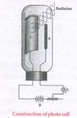
Give the applications photocell.
4.
List out the laws of photoelectric effect. (or) Write any three Laws of Photoelectric Effect
5.
State and obtain Malus’ law. (or) State Malus' Law.
6.
Differentiate between polarised and unpolarised light.
7.
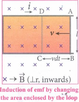
Mention the various energy losses in a transformer.
8.
9.
A solenoid of 500 turns is wound on an iron core of relative permeability 800. The length and radius of the solenoid are 40 cm and 3 cm respectively. Calculate the average emf induced in the solenoid if the current in it changes from 0 to 3 A in 0.4 second.
10.
Emission of electrons by the absorption of heat energy is called ______ emission.
photoelectric
field
thermionic
secondary
11.
The threshold wavelength for a metal surface whose photoelectric work function is 3.313 eV is _____.
4125 \(\mathring { A } \)
3750\(\mathring { A } \)
6000\(\mathring { A } \)
2062.5\(\mathring { A } \)
12.
Two radiations with photon energies 0.9 eV and 3.3 eV respectively are falling on a metallic surface successively. If the work function of the metal is 0.6 eV, then the ratio of maximum speeds of emitted electrons in the two cases will be _____.
1:4
1:3
1:1
1:9
13.
14.
A photoelectric surface is illuminated successively by monochromatic light of wavelength λ and λ /2. If the maximum kinetic energy of the emitted photoelectrons in the second case is 3 times that in the first case, the work function of the material is _____.
\(\frac{hc}{\lambda}\)
\(\frac{2hc}{\lambda}\)
\(\frac{hc}{3\lambda}\)
\(\frac{hc}{2\lambda}\)
15.
The wave associated with a moving particle of mass 3 x 10⁻⁶ g has the same wavelength as an electron moving with a velocity 6 x 10⁶ ms-1. The velocity of the particle is _____.
1.82 x 10⁻¹⁸ms-1
9 x 10⁻²ms-1
3 x 10-31ms-1
1.82 x 10⁻¹⁵ms-1
16.
In an electron microscope, the electrons are accelerated by a voltage of 14 kV. If the voltage is changed to 224 kV, then the de Broglie wavelength associated with the electrons would _____.
increase by 2 times
decrease by 2 times
decrease by 4 times
increase by 4 times
17.
Light transmitted by Nicol prism is, _____.
partially polarised
unpolarised
plane polarised
elliptically polarised
18.
19.
Two point white dots are 1 mm apart on a black paper. They are viewed by eye of pupil diameter 3 mm approximately. The maximum distance at which these dots can be resolved by the eye is_____. [take wavelength of light, λ = 500 nm]
1 m
5 m
3 m
6 m
20.
A plane glass is placed over a various coloured letters (violet, green, yellow, red) The letter which appears to be raised more is _____.
red
yellow
green
violet
21.
In an oscillating LC circuit, the maximum charge on the capacitor is Q. The charge on the capacitor when the energy is stored equally between the electric and magnetic fields is
\(\frac{Q}{2}\)
\(\frac{Q}{\sqrt3}\)
\(\frac{Q}{\sqrt2}\)
Q
22.
In a series RL circuit, the resistance and inductive reactance are the same. Then the phase difference between the voltage and current in the circuit is
\(\frac{\pi}{4}\)
\(\frac{\pi}{2}\)
\(\frac{\pi}{6}\)
zero
23.
A step-down transformer reduces the supply voltage from 220 V to 11 V and increase the current from 6 A to 100 A. Then its efficiency is
1.2
0.83
0.12
0.9
24.
25.
26.
At the given point of time, the earth receives energy from sun at 4 cal cm–2min–1. Determine the number of photons received on the surface of the Earth per cm2 per minute. (Given: Mean wavelength of sun light = 5500 Å )
27.
What is photoelectric effect?
28.
29.
What is polarisation?
30.
How will you define Q-factor?
31.
State Fleming’s right hand rule.
32.
33.
What is meant by electromagnetic induction?
34.
35.
Obtain Einstein’s photoelectric equation with necessary explanation.
36.
What do you mean by electron emission? Explain briefly various methods of electron emission.
37.
Mention different parts of spectrometer and explain the preliminary adjustments.
38.
Explain the experimental determination of refractive index of the material of the prism using spectrometer.
39.
Explain the Young’s double slit experimental setup and obtain the equation for path difference.
40.
Prove law of refraction using Huygens’ principle.
41.
Derive an expression for phase angle between the applied voltage and current in a series RLC circuit.
42.
Explain the construction and working of transformer.
43.
Explain the working of a single-phase AC generator with necessary diagram.
1.
2.
(i) The photons of light of frequency (v) and wavelength (λ) will have energy, given by
\(E=h v=\frac{h c}{\lambda}\)
(ii) The energy of a photon is determined by the frequency of the radiation and not by its intensity and the intensity has no relation with the energy of the individual photons in the beam.
(iii) The photons travel with the velocity of light and its momentum is given by
\(p=\frac{h}{\lambda}=\frac{h v}{c}\)
(iv) Since photons are electrically neutral, they are unaffected by electric and magnetic fields.
(v) When a photon interacts with matter (photon-electron collision), the total energy, total linear momentum, and angular momentum are conserved. Since photons may be absorbed (or) a new photon may be produced in such interactions, the number of photons may not be conserved.
3.
(i) Photo cells are used as switches and sensors.
(ii) Automatic switch on and off of street lights.
(iii) They are used for reproduction of sound in motion pictures
(iv) They are used as timers to measure the speed of athletes during a race.
(v) In photography, they are used to measure the intensity of the given light and to calculate the exact time of exposure.
4.
Laws of photoelectric effect:
(i) For a given surface, the emission of photoelectrons takes place only if the frequency of incident light is greater than a certain minimum frequency called the threshold frequency.
(ii) For a given frequency of incident light, the number of photoelectrons emitted is directly proportional to the intensity of the incident light. The saturation current is also directly proportional to the intensity of incident light.
(iii) Maximum kinetic energy of the photoelectrons is independent of the intensity of the incident light.
(iv) Maximum kinetic energy of the photoelectrons from a given metal is directly proportional to the frequency of incident light.
(v) There is no time lag between the incidence of light and the ejection of photoelectrons.
5.
When a beam of plane polarised light of intensity (Io) is incident on an analyser, the intensity of light (I) transmitted from the analyser varies directly as the square of the cosine of angle between the transmission axes of polariser and analyser.
\(I={ I }_{ o }cos^{ 2 }\theta \)
Consider the plane of polariser and analyser are inclined to each other at an angle ፀ. Let Io be the intensity and 'a' be the amplitude of the electric vector transmitted by the polariser. The amplitude 'a' of the incident light has two rectangular components, (acosθ) and (asinθ) which are the parallel and perpendicular components to the axis of transmission of the analyser. Only the component (acosθ) will be transmitted by the analyzer.
According to Malus's law
\(I\propto \left( acos\theta \right) ^{ 2 }\)
\(I=k\left( acos\theta \right) ^{ 2 }\)
Where k is constant of proportionality,
I = ka2 cos2 θ
I = Io = cos2 θ
Where Io = ka2 is the maximum intensity of light transmitted from the analyser.
6.
| S.No |
Polarised Light |
Unpolarised Light |
|---|---|---|
| (i) | It consists of waves having their electric field vibrations in a single plane normal to the direction of ray. | It consists of waves having their electric field and magnetic field vibrations in all directions normal to the direction of ray. |
| (ii) | Asymmetrical about the ray direction | Symmetrical about the ray direction. |
| (iii) | |It is obtained by converting unpolarised light using polaroids. | Produced by conventional light sources. |
7.
| S.No | Name of the losses | Source of losses | Method to minimise |
| (i) | (a) Core loss (or) Iron loss (or) Hysteresis loss | Transformer core is magnetised and demagnetised repeatedly |
Using steel of high silicon content in making transformer core |
| (b) Eddy current loss | Alternating magnetic flux in the core induces eddy currents in it. |
Using very thin laminations of transformer core. | |
| (ii) | Copper loss | When the electric current flows through windings of transformers, some amount of energy is dissipated due to Joule heating |
Using wires of larger diameter |
| (iii) | Flux leakage | The magnetic lines of primary coil are not completely linked with secondary coil. |
Windings the coils one over the other. |
8.
9.
N = 500 turns; μr = 800;
l = 40 cm = 0.4 m; r = 3 cm = 0.03 m;
di = 3 – 0 = 3 A; dt = 0.4 s
Self inductance,
\(L=\mu { n }^{ 2 }Al\left( \because \mu ={ \mu }_{ o }{ \mu }_{ r };A={ \pi r }^{ 2 };n=\frac { N }{ l } \right) \)
\(=\frac { { \mu }_{ 0 }{ \mu }_{ r }{ N }^{ 2 }\pi { r }^{ 2 } }{ l } \)
\(=\frac { 4\times 3.14\times { 10 }^{ -7 }\times 800\times { 500 }^{ 2 }\times 3.14\times { (3\times 10 }^{ -2 }{ ) }^{ 2 } }{ 0.4 } \)
L=1.77H
Induced emf, ε = -L\(\frac{di}{dt}\)
\(=\frac{1.77\times3}{0.4}\)
ε = -13.275V
10.
(c)
thermionic
11.
\(\lambda_0 =\frac{h c}{\phi} \)
\(=\frac{6.626 \times 10^{-34} \times 3 \times 10^8}{3.313 \times 1.6 \times 10^{-19}} \)
\( =\frac{19.8782400}{5.3} \times 10^{-7} \)
\(\lambda_0 =3.750 \times 10^{-7} \simeq 3750 \stackrel{o}A\)
12.
K.E= hv - Φ
K.E1 = 0.9 - 0.6 = 0.3 eV
K.E2 = 3.3 - 0.6 = 2.7 ev
K.E ∝ v2
\(\frac{0.3}{2.7}=\frac{v^2_1}{v^2_2} \)
\(\frac{v^1}{v^2} =\frac{1}{3}\)
13.
(b)
14.
\(\frac{\mathrm{hc}}{\lambda} =\phi+\mathrm{K} . \mathrm{E} .....(1) \)
\(\frac{2 \mathrm{hc}}{\lambda} =\phi+3 \mathrm{~K} . \mathrm{E}......(2)\)
multiply eqn. (1) by 3, we get
\(\frac{3 \mathrm{hc}}{\lambda} =3\phi+3 \mathrm{~K} . \mathrm{E} .....(3)\)
Subtract eqn. (2) from (3), we get
\(\frac{\mathrm{hc}}{\lambda} =2\phi \)
\(\phi=\frac{ \mathrm{hc}}{2\lambda} \)
15.
\(\lambda_{\mathrm{i}} \frac{1}{\mathrm{mv}} \)
\(\frac{\lambda_p}{\lambda_e} =\frac{m_e v_e}{m_P v_P} \)
\(1 =\frac{9.1 \times 10^{-31} \times 6 \times 10^6}{3 \times 10^{-9} \times v_p} \)
\(\mathrm{v}_{\mathrm{p}} =9.1 \times 10^{-16} \times 2 \)
\(\mathrm{v}_{\mathrm{p}} =18.2 \times 10^{-16} \)
\(\mathrm{v}_{\mathrm{p}} =1.82 \times 10^{-15} \mathrm{~m} \mathrm{~s}^{-1}\)
16.
\(\lambda\propto \frac{1}{\sqrt{V}}\)
\(\frac{\lambda_1}{\lambda_2}=\frac{\sqrt{224\times10^3}}{\sqrt{14\times 10^3}}\)
\(=\sqrt{16}=4\)
\(\lambda_{\mathrm{2}}= \frac{\lambda_1}{4}\)
17.
(c)
plane polarised
18.
(b)
19.
λ = 500 nm = 500 x 10-9 m
x = 3 mm = 3 x 10⁻³ m
a = 1 mm = 1 x 10⁻³ m
\(d=\frac{xa}{1.22 \lambda}\)
\(d=\frac{3 \times1\times10^{-6}}{1.22 \times500\times10^{-9}}\)
\(=\frac{3 \times1\times10^{-6}}{6.10 \times 10^{-7}}\)
\(d=\frac{30}{6.1}=5 m\)
20.
Refractive index for violet is more and wavelength for violet is very low comparing other colours. So, the letter which appears to be raised more is violet.
21.
\(Q_{midpoint}=\frac{Q}{\sqrt{1^2+1^2}}=\frac{Q}{\sqrt2}\)
22.
In RL circuit, tanΦ = \(\frac{X_l}{R}\)
If R = X1, then tanΦ = \(\frac{X_l}{X_l}=1\)
∴ Φ = tan-1(1)=\(\frac{\pi}{4}\)
∴ Phase difference \(=\frac{\pi}{4}\)
23.
\(\mathrm{V}_{\mathrm{P}}=220 \mathrm{~V}, \mathrm{~V}_{\mathrm{s}}=11 \mathrm{~V} \)
\(\mathrm{I}_{\mathrm{P}}=6 \mathrm{~A}, \mathrm{I}_{\mathrm{s}}=100 \mathrm{~A} . \)
\(\text {Efficiency }=\frac{\mathrm{V}_{\mathrm{s}} \mathrm{I}_{\mathrm{s}}}{\mathrm{V}_{\mathrm{P}} \mathrm{I}_{\mathrm{P}}} \)
\(=\frac{11 \times 100}{220 \times 6}=\frac{1100}{220 \times 6}=\frac{5}{6}=0.83\)
24.
(a)
25.
26.
\(P=4 \ \mathrm{cal} \mathrm{} \mathrm{cm}^{-2} \mathrm{~min}^{-1}=4 \times 4.2=16.8 \mathrm{~J} \mathrm{~cm}^{-2} \mathrm{~min}^{-1} \)
\(E=\frac{h c}{\lambda}=\frac{6.626 \times 10^{-34} \times 3 \times 10^{8}}{5500 \times 10^{-10}}=3.6 \times 10^{-19} \mathrm{~J} \)
\(n=\frac{E}{hv}=\frac{16.8}{3.6 \times 10^{-19}}=4.67 \times 10^{19} \)
\(n=4.67 \times 10^{19} \) per cm2 per minute.
27.
The ejection of electrons from the metal plate when illuminated by light or any electromagnetic radiation of suitable wavelength (or frequency) is called photoelectric effect.
28.
29.
The Phenomenon of restricting the vibrations of light to a particular direction perpendicular to the direction of wave propagation motion is called polarization of light.
30.
Q factor is defined as the ratio of voltage across L or C to resonance to the applied voltage
Q - factor = \(\frac{Voltage \ across \ L \ or \ C \ resonance }{Applied \ voltage}\)
\(Q-factor=\frac{X_{L}}{R}=\frac{1}{R}\sqrt\frac{{L}}{C}\)
31.
The thumb, index finger and middle finger of right hand are stretched out in mutually perpendicular directions. If the index finger points the direction of the magnetic field and the thumb indicates the direction of motion of the conductor, then the middle finger will indicate the direction of the induced current.
32.
33.
Whenever the magnetic flux linked with a closed coil changes, an emf is induced and hence an electric current flows in the circuit. This current is called an induced current and the emf giving rise to such current is called an induced emf. This phenomenon is known as electromagnetic induction.
34.
35.
(i) When a photon of energy hv is incident on a metal surface, it is completely absorbed by a single electron and the electron is ejected.
(ii) In this process, a part of the photon energy is used for the ejection of the electrons from the metal surface (photoelectric work function Φ0) and the remaining energy as the kinetic energy of the ejected electron. From the law of conservation of energy,
\(\\ \\ \\ hv=\phi { _{ 0 }+\cfrac { 1 }{ 2 } { mv }^{ 2 } }\) ......(1)
(iii) where m is the mass of the electron and v its velocity.
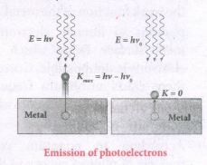
(iv) If we reduce the frequency of the incident light is reduced, the speed or kinetic energy of photo electrons is also reduced. At some frequency v0 of incident radiation, the photo electrons are ejected with almost zero kinetic energy.
Then the equation becomes.
\({ hv }_{ 0 }=\phi _{ 0 }\) ......(2)
(v) Where v0 is the threshold frequency. B rewriting the equation, we get
\(hv={ hv }_{ o }+\cfrac { 1 }{ 2 } { { mv }^{ 2 } }\) ......(3)
The equation is known as einstein's photoelectric equation.
(vi) If the electron does not lose energy by internal collisions, then it is emitted with maximum kinetic energy Kmax. Then
\({ K }_{ max }=\cfrac { 1 }{ 2 } { mv }^{ 2 }_{ max }\) ......(4)
(vii) where vmaxis the maximum velocity of max the electron ejected. The equation (1) is rearranged as follows:
\({ K }_{ max }=hv-{ \phi }_{ 0 }\)
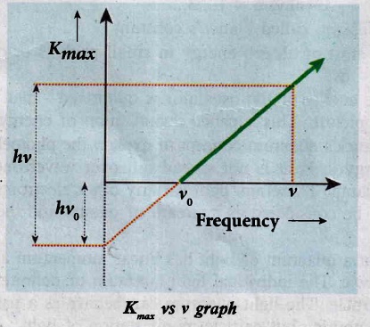
A graph between maximum kinetic energy Kmax of the photoelectron and frequency v of the incident light is a straight line.
36.
(i) In metals, the electrons in the outer most shells are loosely bound to the nucleus. Even at room temperature, there are a large number of free electrons which are moving inside the metal in a random manner. Through they move freely inside the metal they cannot leave the surface of the metal. The reason is that when free electrons reach the surface of the metal they are attracted by the positive nuclei of the metal. It is attractive pull which will not allow free electrons to leave the metallic surface at room temperature.
(ii) In order to leave the metallic surface, the free electrons must cross a potential barrier created by the positive nuclei of the metal. The potential barrier. which prevents free electrons from leading the metallic surface is called surface barrier.
(iii) Whenever an additional energy is given to the free electrons, they will have sufficient energy to cross the surface barrier. And they escape from the metallic surface. The liberation of electrons from any surface of a substance is called electron emission.
(iv) The minimum energy needed for an electron to escape from the metal surface is called work function of that metal.
(a) Thermionic emission
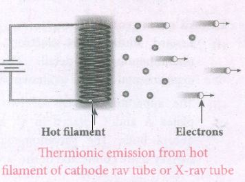
(i) When a metal is heated to a high temperature, the free electrons on the surface of the metal get sufficient energy in the form of thermal energy so that they are emitted from the metallic surface. This type of emission is known a thermonic emission.
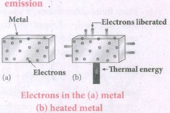
(ii) The intensity of the thermionic emission (the number of electrons emitted) depends on the metal used and its temperature.
(iii) Examples: cathode ray tubes, electron microscopes, X-ray tubes etc.
(b) Field emission
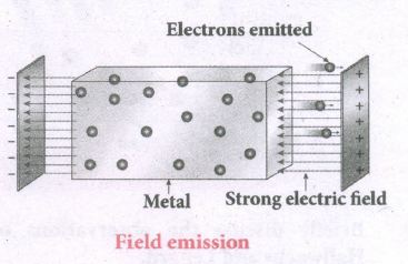
(i) Electric field emission occurs when a very strong electric field is applied across the metal.
(ii) This strong field pulls the free electrons and helps them to overcome the surface barrier of the metal.
(iii) Ex: Field ermssion scanning electron microscopes, Field-emission display etc.
(c) Photo electric emission
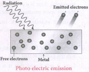
(i) When an electromagnetic radiation of suitable frequency is incident on the surface of the metal, the energy is transferred from the radiation to the free electrons.
(ii) Hence, the free electrons get sufficient energy to cross the surface barrier and the photo electric emission takes place.
(iii) The number of electrons emitted depend on the intensity of the incident radiation.
(iv) Examples: Photo diodes, photo electric cells etc.
(d) Secondary emission
(i) When a beam of fast-moving electrons strikes the surface of the metal, the kinetic energy of the striking electrons is transferred to the free electrons on the metal surface.
(ii) Thus the free electrons get sufficient kinetic energy so that the secondary emission of electron occurs.
(iii) Examples: Image intensifiers, photo multiplier tubes etc.
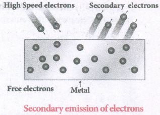
37.
i) The spectrometer is an optical instrument used to analyse the spectra of different sources of light, to measure the wavelength of different colours and to measure the refractive indices of materials of prisms.
ii) It basically consists of three parts namely. They are (i) collimator, (ii) prism table and (iii) Telescope
Adjustments of the spectrometer
(i) The following adjustments must be done in a spectrometer before doing the experiment.
(a) Adjustment of the eyepiece:
The telescope is turned towards an illuminated surface and the eyepiece is moved to and fro until the cross wires are clearly seen.
(b) Adjustment of the telescope:
The telescope is adjusted to' receive parallel rays by turning it towards a distant object and adjusting the distance between the objective lens and the eyepiece to get a clear image on the cross wire.
(c) Adjustment of the collimator:
The telescope is brought in line with the collimator. The distance between the illuminated slit and the lens of the collimator is adjusted until a clear image of the slit is seen at the cross wire.
(d) Levelling the prism table:
The prism table is brought to the horizontal level by adjusting the levelling screws and it is ensured by using sprit level.
38.
The preliminary adjustments of the spectrometer are done. The refractive index of the prism can be determined by measuring the angle of the prism (A) and the angle of minimum deviation (D).
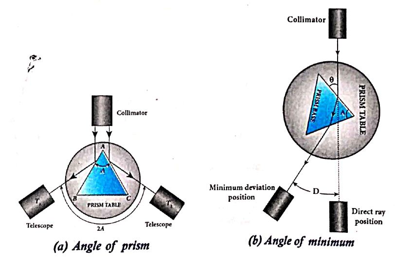
i) Angle of the prism (A):
(i) The prism is placed on the prism table with its refracting angle (A) facing the collimator as shown in Figure (a).
(ii) The slit is illuminated by sodium light (monochromatic light)
(iii)The parallel rays coming from the collimator fall on the two faces AB and AC and get reflected.
(iv) The telescope is rotated to the position T1 and T2 to capture the reflected rays and the two reading are noted
(v) The difference between these two readings gives the angle rotated by the telescope, which is twice the angle of the prism.
(vi) Half of this value gives the angle of the prism A.
ii) Angle of minimum deviation (D):
(i) The prism is placed on the prism table so that the light from the collimator falls on a refracting face, and the refracted image is observed through the telescope as shown in Figure.
(ii) The prism table is now rotated so that the angle of deviation decreases.
(iii) A stage comes when the image stops and returns on further rotation of the prism table.
(iv) This is ensured by looking through the telescope simultaneously. The reading in this position gives the minimum deviation position.
(v) Now, the prism is removed and the telescope is turned to receive the direct ray and the reading is noted.
(vi) The difference between the two readings gives the angle of minimum deviation D.
(vii) The refractive index of the material of the prism n is calculated using the formula,
\(\\ n=\cfrac { sin\left( \frac { A+D }{ 2 } \right) }{ sin\left( \frac { A }{ 2 } \right) } \) ..................(1)
The refractive index of a liquid may be determined in the same way using a hollow glass prism filled with the given liquid.
39.
Experimental setup:
(i) S is a source s1 and s2 the double slits which are at equidistances from 's'. Wavefronts from s1 and s2 spread out and overlap on other side of double slit.
(ii) When a screen is placed at a distance of about 1 meter from the slits, alternate bright and dark fringes which are equally spaced appear on the screen. These are called interference fringes or bands.
(iii) Using an eyepiece the fringes can be seen directly. At the center point O on the screen, waves from s1 and s2 travel equal distances and arrive in-phase as shown in Figure.
(iv) These two waves constructively interfere and bright fringe is observed at O. This is called cental bright fringe.
(v) When one of the slits is closed, The fringes disappear and there in uniform illumination on the screen.
(vi) This shows clearly that the bands are due to interference.
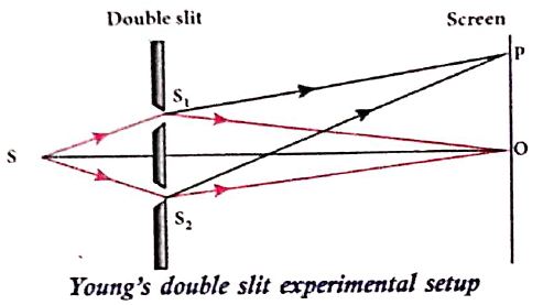
Equation for path difference :
(i) The Let d be the distance between the double slits s1 and s2 which act as coherent sources of wavelength λ.
(ii) A screen is placed parallel to the double slit at a distance D from it.
(iii) P is any point at a distance y from O.
(iv) The waves from S1 and S2 meet at P either in-phase or out-of-phase depending upon the path difference between the two waves.
.JPG)
The path difference \(\delta\) between the light waves from s1 and s2 to the point p is,
\(\delta=\mathrm{S}_{2} \mathrm{P}-\mathrm{S}_{1} \mathrm{P}\)
\(\delta=\mathrm{S}_{2} \mathrm{P}-\mathrm{MP}=\mathrm{S}_{2} \mathrm{M}\) .........(1)
\(\angle \mathrm{OCP}=\angle \mathrm{S}_{2} \mathrm{~S}_{1} \mathrm{M}=\theta\)
In right angle triangle \(\Delta \mathrm{S}_{1} \mathrm{S}_{2} \mathrm{M}\), the path difference S2M = d sin \(\theta\)
\(\delta=d \sin \theta\) ...........(2)
If the angle \(\theta\) is small, \(\sin \theta \approx \tan \theta \approx \theta\)
From the right angle triangle \(\Delta \mathrm{OCP}, \tan \theta=\frac{\mathrm{y}}{\mathrm{D}}\)
The path differences \(\delta=\frac{d y}{D}\) ...........(3)
Based on the condition of the path difference, the point P may have a bright (or) dark fringe
40.
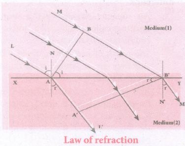
(i) Let us Consider a parallel beam of light is incident on a refracting plane surface XY such as a glass surface as shown in Figure.
(ii) The incident wavefront AB is in rarer medium (1) and the refracted wavefront A'B' is in denser medium (2).
(iii) These wavefronts are perpendicular to the incident rays L, M and refracted rays L', M' respectively.
\(t=\cfrac { BB' }{ { v }_{ 1 } } =\cfrac { AA' }{ { v }_{ 2 } } \) or \(\cfrac { BB' }{ AA' } =\cfrac { { v }_{ 1 } }{ { v }_{ 2 } } \)
(i) The incident rays, the refracted rays and the normal are in the same plane.
(ii) Angle of incidence
i = ∠ NAL = 90o - ∠NAB = ㄥ BAB'
Angle of refraction,
r = ∠ N'B'M = 90o-ㄥN'B'A' =∠ A'B'A
For the two right angle triangles ∆ABB' and ∆AA'B',
\(\cfrac { sini }{ sinr } =\cfrac { \frac { BB' }{ AB' } }{ \frac { AA' }{ AB' } } =\cfrac { BB' }{ AA' } =\cfrac { { v }_{ 1 } }{ { v }_{ 2 } } =\cfrac { \frac { c }{ { v }_{ 2 } } }{ \frac { c }{ { v }_{ 1 } } } \)
(iv) Here, C is speed of light in vacuum. The ratio \(\cfrac { c }{ v } \) is the constant, called refractive index of the medium. The refractive index of medium (1) is,\(\cfrac { c }{ { v }_{ 1 } } ={ n }_{ 1 }\) and that of medium (2) is,\(\cfrac { c }{ { v }_{ 1 } } ={ n }_{ 2 }\) In ratio form,
\(\cfrac { sini }{ sinr } =\cfrac { { n }_{ 2 } }{ { n }_{ 1 } } \) .............(1)
In product form,
n1 sin i = n2 sin r ..........(2)
Hence, the laws of refraction are proved.
41.
(i) Consider a circuit containing a resistor of resistance R, a inductor of inductance L and a capacitor of capacitance C connected across an alternating voltage source (Figure ). The instantaneous value of the alternating voltage is given by the equation
ሀ = Vm sin ωt ......(1)
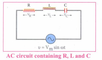
(ii) Let i be the resulting circuit current in the circuit at that instant. As a result, the voltage is developed across R, Land C.
(iii) We know that voltage across R (VR) is in phase with i, voltage across L (VL) leads i by \(\frac { \pi }{ 2 } \) and voltage across C (Vc) lags behind i by \(\frac { \pi }{ 2 } \)
(iv) The phasor diagram is drawn with current as the reference phasor. The current is represented by the phasor \(\vec { OI } \), VR by \(\vec { OA } \); VL by \(\vec { OB } \); Vc by \(\vec { OC } \) as shown in Figure.
(v) The length of these phasors are OI = Im, OA = ImR, OB = ImXL; OC = ImXC
The circuit is either effectively inductive or capacitive or resistive that depends on the value of VL or VC. Let us assume that VL>VC so that nef voltage drop across L-C combination is VL - VC which is represented by a phasor \(\vec { OD } \)
(vi) By parallelogram law, the diagonal \(\vec { OE } \) gives the resultant voltage ሀ of VR and (VL - VC) and its length OE is equal to Vm Therefore,
V2m = V2R + (VL - VC)2 = \(\sqrt { { ({ { I }_{ m }R) } }^{ 2 }+{ ({ I }_{ m }{ X }_{ L }-{ I }_{ m }{ X }_{ C }) }^{ 2 } }=I_m \sqrt {R^2+({X_L-X_C)}^2}\)
or \({ I }_{ m }=\frac { { V }_{ m } }{ \sqrt { R^{ 2 }+({ { X }_{ L }-{ X }_{ C }) }^{ 2 } } } \) ......(2)
\((or) { I }_{ m }=\frac { { V }_{ m } }{ Z } \) where z = \(\sqrt { { R }^{ 2 }+({ { X }_{ L }-{ X }_{ C }) }^{ 2 } } \) ......(3)
(vii) Z is called impedance of the circuit which refers to the effective opposition to the circuit current by the series RLC circuit. The voltage triangle and impedance triangle are given in the Figure.
.JPG)
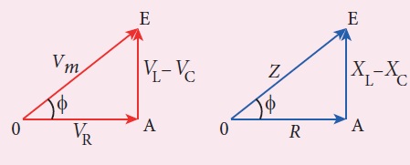
(viii) From phasor diagram, the phase angle between v and i is found out from the following relation
\(tan\phi =\frac { V_{ L }-{ V }_{ C } }{ { V }_{ R } } =\frac { X_{ L }-{ V }_{ C } }{ R } \)
Special cases:
(i) If XL > XC (XL - XC) is positive and phase angle \(\phi \) is also positive. It means that the applied voltage leads the current by \(\phi \) (or current lags behind voltage by \(\phi\)). The circuit is inductive.
∴v = Vm sin ωt; i = Im sin(ωt - \(\phi \))
(ii) If XL < XC (XL - XC) is negative and\(\phi \) is also negative. Therefore current leads voltage by \(\phi \) (or voltage lags behind current by\(\phi \)) and the circuit is capacitive.
∴ = Vm sin ωt; i = Im sin(ωt + \(\phi \))
(ii) If XL = XC \(\phi \) is zero. Therefore current and voltage are in the same phase and the circuit is resistive
∴v = Vm sin ωt, i = Im sinωt
42.
Principle:
The principle of transformer is the mutual induction between two coils. That is, when an electric current passing through a coil changes with time, an emf is induced in the neighbouring coil.
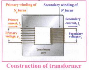
Construction:
(i) In the simple construction of transformers, there are two coils of high mutual inductance wound over the same transformer core.
(ii) The core is generally laminated and is made up of a good magnetic material like silicon steel. Coils are electrically insulated but magnetically linked via transformer core.
(iii) The coil across which alternating voltage is applied is called primary coil P and the coil from which output power is drawn out is called secondary coil S. The assembled core and coils are kept in a container which is filled with suitable medium for better insulation and cooling purpose.
Working:
(i) If the primary coil is connected to a source of alternating voltage, an alternating magnetic flux is set up in the laminated core.
(ii) If there is no magnetic flux leakage, then whole of magnetic flux linked with primary coil is also linked with secondary coil.
(iii) This means that rate at which magnetic flux changes through each turn is same for both primary and secondary coils.
(iv) As a result of flux change, emf is induced in both primary and secondary coils. The emf induced in the primary coil vp or back of εp is given by,
vp = εp = -Np \(\frac{dФ_B}{dt}\) ........(1)
(vi) The frequency of alternating magnetic flux in the core is same as the frequency of the applied voltage. Therefore, induced emf in secondary will also have same frequency as that of applied voltage. The emf induced in the secondary coil εs is given by ,
εs = -Ns\(\frac{dФ_B}{dt}\)
Where Np and Ns are the number of turns in the primary and secondary coil respectively. If the secondary circuit is open, then εs = ሀs where u is the voltage ሀs across secondary coil
ሀs = εs = -Ns \(\frac{dФ_B}{dt}\) ........(2)
From equations (1) and (2),
\(\frac{v_s}{v_p}=\frac{N_s}{N_p}\) = K ........(3)
(vii) This constant K is known as voltage transformation ratio. For an ideal transformer, input power vpip= Output power vsis
where ip and is are the currents in the primary and secondary coil respectively.
(ix) Therefore,
\(\frac{V_s}{V_p}=\frac{N_s}{N_p}=\frac{I_p}{I_s}\) ........(4)
Equation (4) is written in terms of amplitude of corresponding quantities
\(\frac{V_s}{V_p}=\frac{N_s}{N_p}=\frac{I_p}{I_s}\) = K
i) If Ns> Np (or K > 1), ∴ Vs > Vp and Is < Ip This is the case of step-up transformer in which voltage is increased and the corresponding current is decreased.
ii) If Ns< Np (or K < 1), ∴ Vs < Vp and Is > Ip This is step-down transformer where voltage is decreased and the current is increased.
Efficiency of a transformer:
The efficiency η of a transformer is defined as the ratio of the useful output power to the input power. Thus,
\(η=\frac{Outpur \ power}{Input \ power}\times100% \) % ....(5)
43.
.JPG)
Working: The loop PQRS is stationary and is perpendicular to the plane of the paper. When field windings are excited, magnetic field is produced around it. Let the field magnet be rotated in clockwise direction by some external means (Figure).
(i) Assume that initial position of the field magnet is horizontal. At that instant, the direction of magnetic field is perpendicular to the plane of the loop PQRS. The induced emf is zero. This is represented by origin O in the graph between induced emf and time angle.
(ii) When field magnet rotates through 90°, magnetic field becomes parallel to PQRS. The induced emfs across PQ and RS would become maximum. Since they are connected in series, emfs are added up and the direction of total induced emf is given by Flemin's right hand rule.
.JPG)
(iii) Care has to be taken while applying this rule, the thumb indicates the direction of the motion of the conductor with respect to field. For clockwise rotating poles, the conductor appears to be rotating anticlockwise. Hence, thumb should point to the left. The direction of the induced emf is at right angles to the plane of the paper. For PQ, it is inwards and for RS outwards. Therefore, the current flows along PQRS. The point A in the graph represents this maximum emf.
(iv) For the rotation of 180° from the initial position, the field is again perpendicular to PQRS and the induced emf becomes zero. This is represented by point B.
(v) The field magnet becomes again parallel to PQRS for 270° rotation of field magnet. The induced emf is maximum but the direction is reversed. Thus the current flows along SRQP. This is represented by point C
(vi) On completion of 360°, the induced emf becomes zero and is represented by the point D. From the graph, it is clear that emf induced in PQRS is alternating in nature.
(vii) Therefore, when field magnet completes one rotation, induced emf in PQRS finishes one cycle.

12th Standard Syllabus & Materials
12th Standard
TN 12th Computer Applications களப்பெயர் முறைமை (DNS) Sample Question Papers Study Material - QB365 Set A
NEW12th Standard
TN 12th Computer Applications வலையமைப்பு எடுத்துக்காட்டுகள் மற்றும் நெறிமுறைகள் Sample Question Papers Study Material - QB365 Set A
NEW12th Standard
TN 12th Computer Applications கணினி வலையமைப்பு ஓர் அறிமுகம் Sample Question Papers Study Material - QB365 Set A
NEW12th Standard
TN 12th Computer Applications PHP-உடன் MySQL-ஐ இணைத்தல் Sample Question Papers Study Material - QB365 Set A



Tamilnadu Stateboard 12th Standard Subjects

Maths

Chemistry
Physics

Biology

Computer Science

Business Maths and Statistics

Economics

Commerce

Accountancy

History

Computer Applications
Biology
Computer Technology
Computer Applications
Computer Science
Business Maths and Statistics
Commerce
Economics
Maths
Chemistry
Physics
Computer Technology
History
Accountancy

Tamil

English

French
Tamilnadu Stateboard Standards


