
 100% FREE ACCESS
12th Standard Syllabus & Materials
12th Standard
TN 12th Computer Applications மின்னணு தரவு பரிமாற்றம் Sample Question Papers Study Material - QB365 Set A
NEW12th Standard
TN 12th Computer Applications மின் - வணிக பாதுகாப்பு அமைப்புகள் Sample Question Papers Study Material - QB365 Set A
NEW12th Standard
TN 12th Computer Applications மின்னணு செலுத்தல் முறைகள் Sample Question Papers Study Material - QB365 Set A
NEW12th Standard
TN 12th Computer Applications மின் - வணிகம் Sample Question Papers Study Material - QB365 Set A
NEW12th Standard
TN 12th Computer Applications திறந்த மூல கருத்துருக்கள் Sample Question Papers Study Material - QB365 Set A
NEW12th Standard
TN 12th Computer Applications வலையமைப்பு வடமிடல் Sample Question Papers Study Material - QB365 Set A

Published on: 28/11/2025
Download Tamil Nadu 12th Standard Physics question papers, model tests, one-mark questions, important questions, and public exam papers in PDF format. Free study materials and answer keys for TN State Board students.
Questions + Answers key
Take MCQ Physics Test
1.
List the uses of polaroids.
2.
State and obtain Malus’ law. (or) State Malus' Law.
3.
Derive the relation between f and R for a spherical mirror.
4.
Compute the torque experienced by a magnetic needle in a uniform magnetic field.
5.
Obtain an expression for motional emf from Lorentz force.
6.
Write short notes on
(a) microwaves
(b) X - rays
(c) Radio waves
(d) Visible spectrum
7.
Obtain Gauss law from Coulomb’s law.
8.
State and explain Kirchhoff ’s rules
9.
The resistance of a wire is 20 Ω. What will be new resistance, if it is stretched uniformly 8 times its original length?
10.
Dimension of Resistance is _____.
ML2 T-3 A-2
ML2 T-1 A-1
ML2 T-2A-3
ML2 T-1A-2
11.
12.
Two point white dots are 1 mm apart on a black paper. They are viewed by eye of pupil diameter 3 mm approximately. The maximum distance at which these dots can be resolved by the eye is_____. [take wavelength of light, λ = 500 nm]
1 m
5 m
3 m
6 m
13.
An air bubble in glass slab of refractive index 1.5 (near normal incidence) is 5 cm deep when viewed from one surface and 3 cm deep when viewed from the opposite face. The thickness of the slab is ______.
8 cm
10 cm
12 cm
16 cm
14.
An object is placed in front of a convex mirror of focal length off and the maximum and minimum distance of an object from the mirror such that the image formed is real and magnified.
2f and c
c and \(\infty\)
f and O
None of these
15.
Potentiometer is an instrument used for the measurement of____________
current
resistance
capacitance
potential difference
16.
A force of 40 N is acting between two charges in air if the space between then is filled with glass εr = 8. Then the force between then is __________
20 N
10 N
5 N
the same and does not change
17.
The vertical component of Earth’s magnetic field at a place is equal to the horizontal component. What is the value of angle of dip at this place?
30°
45°
60°
90°
18.
A circular coil of radius 5 cm and 50 turns carries a current of 3 ampere. The magnetic dipole moment of the coil is nearly ____.
1.0 A m2
1.2 A m2
0.5 A m2
0.8 A m2
19.
In a series resonant RLC circuit, the voltage across 100 Ω resistor is 40 V. The resonant frequency ω is 250 rad/s. If the value of C is 4 µF, then the voltage across L is
600 V
4000 V
400 V
1 V
20.
21.
Which of the following is NOT true for electromagnetic waves?
it transport energy
it transport momentum
it transport angular momentum
in vacuum, it travels with different speeds which depend on their frequency
22.
Rank the electrostatic potential energies for the given system of charges in increasing order
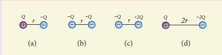
1 = 4 < 2 < 3
2 = 4 < 3 < 1
2 = 3 < 1 < 4
3 < 1 < 2 < 4
23.
The total electric flux for the following closed surface which is kept inside water
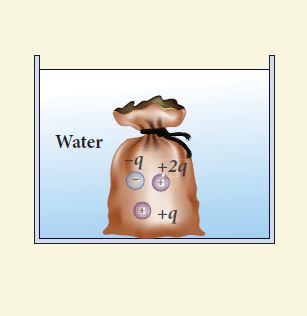
\(\frac { 80q }{ { \varepsilon }_{ 0 } } \)
\(\frac { q }{ { 40\varepsilon }_{ 0 } } \)
\(\frac { q }{ { 80\varepsilon }_{ 0 } } \)
\(\frac { q }{ { 160\varepsilon }_{ 0 } } \)
24.
What is the value of resistance of the following resistor?
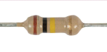
100 k Ω
10 k Ω
1 k Ω
1000 k Ω
25.
Explain the Young’s double slit experimental setup and obtain the equation for path difference.
26.
Obtain lens maker’s formula and mention its significance.
27.
28.
Obtain the magnetic field at a point on the equatorial line of a bar magnet.
29.
Obtain a relation for the magnetic field at a point along the axis of a circular coil carrying current using Biot-Savart law.
30.
Explain the construction and working of transformer.
31.
Explain the types of emission spectrum.
32.
Derive the expression for resultant capacitance, when capacitors are connected in series and in parallel.
33.
Obtain the expression for electric field due to an charged infinite plane sheet.
34.
35.
State Fleming's left hand rule.
36.
State Huygens’ principle.
37.
What is dispersion?
38.
39.
State Coulomb’s inverse law.
40.
41.
What is displacement current?
42.
Define ‘capacitance’. Give its unit.
43.
1.
(i) Polaroids are used in goggles and cameras to avoid glare of light.
(ii) Polaroids are useful in 3D pictures i.e., in holography.
(iii) Polaroids are used to improve contrast in old oil paintings.
(iv) Polaroids are used in optical stress analysis.
(v) Polaroids are used as window glasses to control the intensity of incoming light.
(vi) Polarised laser beam acts as needle to read/ write in compact discs (CDs).
(vii) Polarised lights is used in liquid crystal display (LCD).
2.
When a beam of plane polarised light of intensity (Io) is incident on an analyser, the intensity of light (I) transmitted from the analyser varies directly as the square of the cosine of angle between the transmission axes of polariser and analyser.
\(I={ I }_{ o }cos^{ 2 }\theta \)
Consider the plane of polariser and analyser are inclined to each other at an angle ፀ. Let Io be the intensity and 'a' be the amplitude of the electric vector transmitted by the polariser. The amplitude 'a' of the incident light has two rectangular components, (acosθ) and (asinθ) which are the parallel and perpendicular components to the axis of transmission of the analyser. Only the component (acosθ) will be transmitted by the analyzer.
According to Malus's law
\(I\propto \left( acos\theta \right) ^{ 2 }\)
\(I=k\left( acos\theta \right) ^{ 2 }\)
Where k is constant of proportionality,
I = ka2 cos2 θ
I = Io = cos2 θ
Where Io = ka2 is the maximum intensity of light transmitted from the analyser.
3.
Relation between f and R:
C ⇒ Center of curvature
F ⇒ Principal focus
i ⇒ Angle of incidence
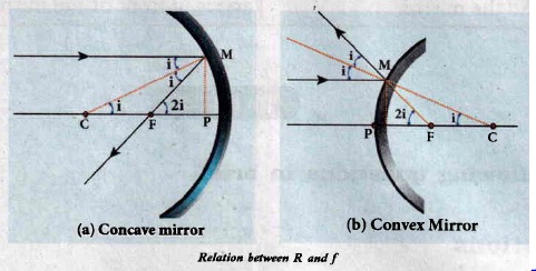
The angles
\(\tan i=\frac{P M}{P C} \text { and } \tan 2 i=\frac{P M}{P F}\)
As the angles are small, tan i = i and tan 2i = 2i.
\(\mathrm{i}=\frac{\mathrm{PM}}{\mathrm{PC}} \text { and } 2 \mathrm{i}=\frac{\mathrm{PM}}{\mathrm{PF}}\)
Simplifying further,
\(2 \frac{\mathrm{PM}}{\mathrm{PC}}=\frac{\mathrm{PM}}{\mathrm{PF}} ; 2 \mathrm{PF}=\mathrm{PC}, \mathrm{R}=2 \mathrm{f}\)
PF is focal length f and PC is the radius of curvature R.
R = 2f (or) f = R/2
4.
i) Consider a bar magnet of length 2l and pole strength qm
ii) Force experienced by the magnet at each pole is qm B (equal) in opposite direction.
iii) So, magnet experiences a torque.
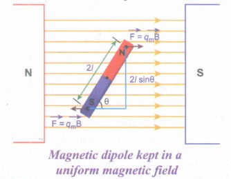
The force experienced by north pole,
\(\vec { { F }_{ N } } ={ q }_{ m }\vec { B } \)
The force experienced by south pole,
\(\vec { { F }_{ S } } =-{ q }_{ m }\vec { B } \)
∴ The net force acting on the dipole is,
\(\vec { F } =\vec { { F }_{ N } } +\vec { F_{ S } } =\vec { 0 } \)
The moment of force or torque experienced by north and south pole about point O is,
\(\vec { \tau } =\vec { ON } \times \vec { { F }_{ N } } +\vec { OS } \times \vec { { F }_{ S } } \)
\(\vec { \tau } =\vec { ON } \times { q }_{ m }\vec { B } +\vec { OS } \times (-{ q }_{ m }\vec { B } )\)
By using right hand cork screw rule, we conclude that the total torque is pointing into the paper. Since the magnitudes \(|\vec { ON } |=|\vec { OS } |=l\) and \(|{ q }_{ m }\vec { B } |=|-{ q }_{ m }\vec { B } |\).
The magnitudes of total torque about point O is
ፒ = l x qmB sinθ + l x qmB sinθ
ፒ = 2l x qmB sinθ
ፒ = pmB sinθ (∴ qm x 2l = pm)
In vector notation, \(\vec { \tau } =\vec { { p }_{ m } } \times \vec { B } \).
5.
(i) Consider a straight conducting rod AB of length I in a uniform magnetic field \(\vec { B } \) which is directed perpendicularly into the plane of the paper.
(ii) The length of the rod is normal to the magnetic field. Let the rod move with a constant velocity \(\vec { v } \) towards right side
(iii) When the rod moves, the free electrons present in it also move with same velocity \(\vec { v } \) in \(\vec { B } \). As a result, the Lorentz force acts on free electrons in the direction from B to A and is given by the relation
.JPG)
\({ \vec { F } }_{ B }=-e(\vec v\times \vec { B } )\)
(iv) The action of this Lorentz force is to accumulate the free electrons at the end A. This accumulation of free electrons produces a potential difference across the rod which in turn establishes an electric field \(\vec { E } \) directed along BA
(v) Due to the electric field \(\vec { E } \), the coulomb force starts acting on the free electrons along AB and is given by
\({ \vec { F } }_{ E }=-e\vec { F } \)
(vi) The magnitude of the electric field \(\vec { E } \) keeps on increasing as long as accumulation of electrons at the end A continues. The force \({ \vec { F } }_{ E }\) also increases until equilibrium is reached.
(vii) At equilibrium, the magnetic Lorentz force \({ \vec { F } }_{ B }\) and the coulomb force \({ \vec { F } }_{ E }\) balance each other and no further accumulation of free electrons at the end A takes place.
| \(\left| { \vec { F } }_{ B } \right| =\left| { \vec { F } }_{ E } \right| \) \(\left| -e(\vec { v } \times \vec { B } ) \right| =\left| -e\vec { E } \right| \) vB Sin 900 = E ⇒vB = E |
The potential difference between two ends of the rod is
V = El
V = vBl
Thus, the Lorentz force on the free electrons is responsible to maintain this potential difference and hence produces an emf
ε = Blv
As this emf is produced due to the movement of the rod, it is often called as motional emf. If the ends A and B are connected by an external circuit or total resistance R, then current \(i=\frac {ε}{R}=\frac{Blv}{R}\)flows in it. The direction of the current is found from right-hand thumb rule.
6.
(a) Microwaves:
It is produced by special vacuum tubes such as klystron, magnetron and gunn diode. The frequency range of microwaves is 109 Hz to 1011 Hz. These waves undergo reflection and can be polarised.
Uses:
It is used in radar system for aircraft navigation, speed of the vehicle, microwave oven for cooking and very long distance wireless communication through satellites.
(b) X-rays:
lt is produced when there is sudden stopping of high speed electrons at high-atomic number target, and also by electronic transitions among the innermost orbits of atoms. The frequency range of X-rays is from 1017 Hz to 1019 Hz. X-rays have more penetrating power than ultraviolet radiation.
Uses:
X-rays are used extensively in studying structures of inner atomic electron shells and crystal structures. It is used in detecting fractures, diseased organs, formation of bones and stones, observing the progress of healing bones. Further, in a finished metal product, it is used to detect faults, cracks, flaws and holes.
(c) Radio waves:
It is produced by accelerated motion of charges in conducting wires. The frequency range is from few Hz to 109 Hz. It obeys reflection and diffraction.
Uses:
It is uses in radio and television communication systems and also in cellular phones to transmit voice communication in the ultra high frequency band.
(d) Visible light:
Visible light is produced by incandescent bodies and also it is radiated by excited atoms in gases. The frequency range is from 4 x 10¹⁴ Hz to 8 x 10¹⁴ Hz. It obeys the laws of interference, diffraction and can be polarised. It exhibits photo-electric effect also.
Uses:
It can be used to study the structure of molecules, arrangement of electrons in external shells of atoms and it causes sensation of vision.
7.
Gauss law:
(i) A positive point charge Q is surrounded by an imaginary sphere of radius r as shown in Figure. then the total electric flux through the closed surface of the sphere is
\(\Phi_E =\oint { \vec { E } .d\vec { A } =\oint { Ed } Acos\theta } \) .....(1)
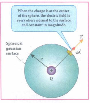
(ii) The electric field of the point charge is directed radially outward at all points on the surface of the sphere. Therefore, the direction of the area element \(d\vec { A } \) is along the electric field \(\vec { E } \) and θ = 0o.
\(\\ \Phi_E =\oint { EdA } \) Since cos0o = 1 ......(2)
iii) E is uniform on the surface of the sphere,
\(\\ \Phi_E=E\oint { dA } \) .......(3)
Substituting for \(\oint { dA=4{ \pi r }^{ 2 } } \) and \(E=\frac { 1 }{ 4\pi { \varepsilon }_{ 0 } } \frac { Q }{ { r }^{ 2 } } \) in eqn (3), we get
\(\therefore \phi E=4{ \pi r }^{ 2 }E\)
\({ \phi }_{ E }=\frac { 1 }{ 4\pi { \varepsilon }_{ 0 } } \frac { Q }{ { r }^{ 2 } } \times { 4\pi r }^{ 2 }=4\pi \frac { 1 }{ 4\pi { \varepsilon }_{ 0 } } Q\)
\({ \phi }_{ E }=\frac { Q }{ { \varepsilon }_{ 0 } } \) .....(4)
The equation (4) is called as Gauss's law.
8.
Kirchhoff's First rule: (current rule)
(i) It states that the algebraic sum of the currents at any junction of a circuit is zero. It is a statement of law of conservation of electric charge.
(ii) All charges that enter a given junction in a circuit must leave that junction since charge cannot build up or disappear at a junction. By convention current entering the junction is taken as positive and current leaving the junction is taken as negative.
Applying law to the junction A in Figure.
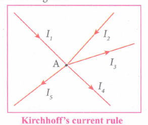
\({ I }_{ 1 }+{ I }_{ 2 }-{ I }_{ 3 }-{ I }_{ 4 }-{ I }_{ 5 }=0\)
(or)
\({ I }_{ 1 }+{ I }_{ 2 }=I_{ 3 }+{ I }_{ 4 }+{ I }_{ 5 }\)
Kirchhoff's Second rule (Voltage rule or Loop rule)
(i) It states that in a closed circuit the algebraic sum of the products of the current and resistance of each part of the circuit is equal to the total emf included in the circuit.
(ii) This rule follows from the law of conservation of energy for an isolated system (The energy supplied by the emf sources is equal to the sum of the energy delivered to all resistors).
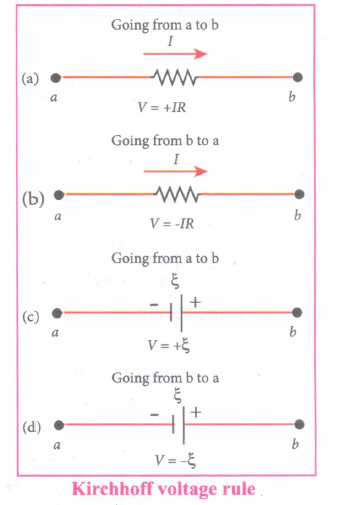
(iii) Kirchhof's voltage rule has to be applied only when all currents in the circuit reach a steady state condition.
(iv) The current in the various branches are constant. The product of current and resistance is taken as positive when the direction of the current is followed.
(v) Suppose if the direction of current is opposite to the direction of the loop, then product of current and voltage across the resistor is negative. It is shown in Figure (a) and (b).
(vi) The emf is considered positive when proceeding from the negative to the positive terminal of the cell.
9.
R1 = 20 Ω, R2 = ?
Let the original length of the wire (l1) be l.
New length, l2 = 8l1 (i.,e) l2 = 8l
Original resistance, R1 = \(\rho \frac { { l }_{ 1 } }{ { A }_{ 1 } } \)
New resistance R2 = \(\rho \frac { { l }_{ 2 } }{ { A }_{ 2 } } =\frac { \rho (8l) }{ { A }_{ 2 } } \)
Though the wire is stretched, its volume is unchanged.
Initial volume = Final volume
A1l1 = A2l2 , A1l = A2(8l)
\(\frac { { A }_{ 1 } }{ { A }_{ 2 } } =\frac { 8l }{ l } =8\)
By dividing equation R2 by equation R1, we get
\(\frac { { R }_{ 2 } }{ { R }_{ 1 } } =\frac { \rho (8l) }{ { A }_{ 2 } } \times \frac { { A }_{ 1 } }{ \rho l } \)
\(\frac { { R }_{ 2 } }{ { R }_{ 1 } } =\frac { { A }_{ 1 } }{ { A }_{ 2 } } \times 8\)
Substituting the value of \(\frac { { A }_{ 1 } }{ { A }_{ 2 } } \), we get
\(\frac { { R }_{ 2 } }{ { R }_{ 1 } } =8\times 8=64\)
R2 = 64 x 20 = 1280 Ω
Hence, stretching the length of the wire has increased its resistance.
10.
\(R=\frac{V}{I}=\frac{W}{q I}=\frac{W}{I t \times I}=\frac{W}{I^2 t}\)
Dimension of \( \mathrm{W} \rightarrow\left[\mathrm{ML}^2 \mathrm{~T}^{-2}\right] \)
Dimension of \( I \rightarrow[A] \)
Dimension of \(t \rightarrow[\mathrm{T}]\)
Hence,
\( [R]=\frac{\left.\mid \mathrm{ML}^2 \mathrm{~T^-2}\right]}{\left[\mathrm{A}^2 \mathrm{~T}\right]}=\left[\mathrm{ML}^2 \mathrm{~T}^{-3} \mathrm{~A}^{-2}\right] \)
11.
(b)
12.
λ = 500 nm = 500 x 10-9 m
x = 3 mm = 3 x 10⁻³ m
a = 1 mm = 1 x 10⁻³ m
\(d=\frac{xa}{1.22 \lambda}\)
\(d=\frac{3 \times1\times10^{-6}}{1.22 \times500\times10^{-9}}\)
\(=\frac{3 \times1\times10^{-6}}{6.10 \times 10^{-7}}\)
\(d=\frac{30}{6.1}=5 m\)
13.
Apparent depth = 3 + 5 = 8 cm
Real depth = thickness of the slab = t
n = 1.5
\(n=\frac{Real \ depth}{Apparent \ depth}\)
\(\therefore 1.5=\frac{t}{8}\)
t = 1.5 x 8
t = 12 cm
14.
Convex Mirror is diverging in nature and for all positions of objects, convex mirror forms virtual and erect image.
15.
(a)
current
16.
(c)
5 N
17.
\(tan \ I=\frac{B_V}{B_H}=1\)
∴ I = 45o
18.
Dipole moment, \(\vec{p}_m=n\times I\times\vec{A}\)
\(\vec{p}_m\) = 50 x 3 x 3.14 x 25 x 10-4 ≈ 1.2 A m2
19.
\(\omega=250 \mathrm{rad} / \mathrm{s}, C=4 \times 10^{-} \mathrm{F} \)
\(R=100 \Omega, \quad \mathrm{V}_{\mathrm{R}}=40 \mathrm{~V} \)
\(\therefore I_{\mathrm{R}}=\frac{V_R}{100}=\frac{40}{100}=0.4 \mathrm{~A} \)
\(\omega=\frac{1}{\sqrt{L C}} \)
\(\omega^2=\frac{1}{L C} \)
\((250)^2=\frac{1}{L \times 4 \times 10^{-6}} \)
\(L=\frac{1}{4 \times(250)^2 \times 10^{-6}} \)
\(=\frac{1}{4 \times 250 \times 250 \times 10^{-6}} \)
\(=\frac{1}{1000 \times 10^{-6} \times 250} \)
\(=\frac{10^3}{250}=\frac{1000}{250}=4 \mathrm{H}\)
Voltage acnoss L, Vt = IXL
VL = l x L x ω
= 0.4 x 4 x 250
0.4 x 1000 = 400 V
20.
(a)
21.
(d)
in vacuum, it travels with different speeds which depend on their frequency
22.
\(U=\frac{1}{4\piε_0}\frac{q_1q_2}{r_{12}}\)
\(i) U=\frac{1}{4\piε_0}\frac{Q(-Q)}{r}=\frac{1}{4\piε_0}[\frac{-Q^2}{r}]\)
\(ii) U=\frac{1}{4\piε_0}\frac{(-Q)(-Q)}{r}=\frac{1}{4\piε_0}[\frac{Q^2}{r}]\)
\(iii) U=\frac{1}{4\piε_0}\frac{Q(2Q)}{r}=\frac{1}{4\piε_0}[\frac{2Q^2}{r}]\)
\(iv) U=\frac{1}{4\piε_0}\frac{Q(-2Q)}{2r}=\frac{1}{4\piε_0}[\frac{-Q^2}{r}]\)
From the values, 1 = 4 < 2 < 3
23.
\(Φ=\frac { q_{net} }{ { \varepsilon }_{ 0 } } \)
qnet = - q + q + 2q = 2q
Relative permittivity of water = 80
\(\therefore Φ=\frac { q }{{ \varepsilon }_{ r } { \varepsilon }_{ 0 } } \)
\(=\frac{2q}{{ 80 \times \varepsilon }_{ 0 }}=\frac{q}{{ 40 \varepsilon }_{ 0 }}\)
24.
Brown - 1
Black - 0
Yellow - 104
(∴ R = 10 x 104 Ω = 100 kΩ)
25.
Experimental setup:
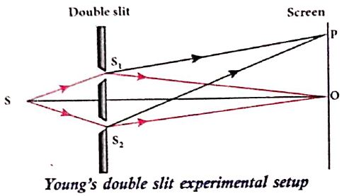
(i) S is a source s1 and s2 the double slits which are at equidistances from 's'. Wavefronts from s1 and s2 spread out and overlap on other side of double slit.
(ii) When a screen is placed at a distance of about 1 meter from the slits, alternate bright and dark fringes which are equally spaced appear on the screen. These are called interference fringes or bands.
(iii) Using an eyepiece the fringes can be seen directly. At the center point O on the screen, waves from s1 and s2 travel equal distances and arrive in-phase as shown in Figure.
(iv) These two waves constructively interfere and bright fringe is observed at O. This is called cental bright fringe.
(v) When one of the slits is closed, The fringes disappear and there in uniform illumination on the screen.
(vi) This shows clearly that the bands are due to interference.
Equation for path difference :
(i) The Let d be the distance between the double slits s1 and s2 which act as coherent sources of wavelength λ.
(ii) A screen is placed parallel to the double slit at a distance D from it.
(iii) P is any point at a distance y from O.
(iv) The waves from S1 and S2 meet at P either in-phase or out-of-phase depending upon the path difference between the two waves.
.JPG)
The path difference \(\delta\) between the light waves from s1 and s2 to the point p is,
\(\delta=\mathrm{S}_{2} \mathrm{P}-\mathrm{S}_{1} \mathrm{P}\)
\(\delta=\mathrm{S}_{2} \mathrm{P}-\mathrm{MP}=\mathrm{S}_{2} \mathrm{M}\) .........(1)
\(\angle \mathrm{OCP}=\angle \mathrm{S}_{2} \mathrm{~S}_{1} \mathrm{M}=\theta\)
In right angle triangle \(\Delta \mathrm{S}_{1} \mathrm{S}_{2} \mathrm{M}\), the path difference S2M = d sin \(\theta\)
\(\delta=d \sin \theta\) ...........(2)
If the angle \(\theta\) is small, \(\sin \theta \approx \tan \theta \approx \theta\)
From the right angle triangle \(\Delta \mathrm{OCP}, \tan \theta=\frac{\mathrm{y}}{\mathrm{D}}\)
The path differences \(\delta=\frac{d y}{D}\) ...........(3)
Based on the condition of the path difference, the point P may have a bright (or) dark fringe
26.
(i) Let us consider a thin lens made up of a medium of refractive index n2 is placed in a medium of refractive index n1. Let R1 and R2 be the radii of curvature of two spherical surfaces (1) and (2) respectively and P be the pole.
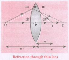
(ii) Consider a point object 'O' on the principal axis. A paraxial ray from 'O' which falls very close to P, after refraction at the surface (1) forms image at 1'.
(iii) Before it does so, it is again refracted by the surface (2). Therefore the final image is formed at I.
(iv) The general equation for the refraction at a single spherical surface is given from Equation,
\(\cfrac { { n }_{ 2 } }{ v } -\cfrac { { n }_{ 1 } }{ v} =\cfrac { \left( { n }_{ 2 }-{ n }_{ 1 } \right) }{ { R } } \)
For the refracting surface (1), the light goes from n1 to n2
\(\cfrac { { n }_{ 2 } }{ v' } -\cfrac { { n }_{ 1 } }{ u } =\cfrac { \left( { n }_{ 2 }-{ n }_{ 1 } \right) }{ { R }_{ 1 } } \) .....(1)
For the refracting surface (2), the light goes from n2 to n1
\(\frac{n_{1}}{v}+\frac{n_{2}}{v^{\prime}}=\frac{\left(n_{1}-n_{2}\right)}{R_{2}}\) ......(2)
For surface (2) I' acts as virtual object.
Adding the above two equations (1) and (2)
\(\cfrac { { n }_{ 1 } }{ v } -\cfrac { { n }_{ 1 } }{ u } =\left( { n }_{ 2 }-{ n }_{ 1 } \right) \left( \cfrac { 1 }{ { R }_{ 1 } } -\cfrac { 1 }{ { R }_{ 2 } } \right) \)
on further simplifying and rearranging,
\(\cfrac { 1 }{ v } -\cfrac { 1 }{ u } =\left( \cfrac { { n }_{ 2 }-{ n }_{ 1 } }{ { n }_{ 1 } } \right) \left( \cfrac { 1 }{ { R }_{ 1 } } -\cfrac { 1 }{ { R }_{ 2 } } \right) \)
\(\cfrac { 1 }{ v } -\cfrac { 1 }{ u } =\left( \cfrac { { n }_{ 2 } }{ n_{ 1 } } -1 \right) \left( \cfrac { 1 }{ { R }_{ 1 } } -\cfrac { 1 }{ { R }_{ 2 } } \right) \) ....(3)
If the object is at infinity, the image is formed at the focus of the lens. Thus, for u = \(\infty\), v = f. Then the equation becomes.
\(\cfrac { 1 }{ f } -\cfrac { 1 }{ \infty } =\left( \cfrac { { n }_{ 2 } }{ { { n }_{ 1 } } } -1 \right) \left( \cfrac { 1 }{ { R }_{ 1 } } -\cfrac { 1 }{ { R }_{ 2 } } \right) \)
\(\cfrac { 1 }{ f } =\left( \cfrac { { n }_{ 2 } }{ { n }_{ 1 } } -1 \right) \left( \cfrac { 1 }{ { R }_{ 1 } } -\cfrac { 1 }{ { R }_{ 2 } } \right) \) ......(4)
If the lens is kept in air, then we can take n2 = n and n1 = 1. So the equation (4) becomes,
\(\\ \cfrac { 1 }{ f } =\left( n-1 \right) \left( \cfrac { 1 }{ { R }_{ 1 } } -\cfrac { 1 }{ { R }_{ 2 } } \right) \) ..(5)
The above equation is called the lens maker's formula.
Significance:
It tells the lens manufacturers what curvature is needed to make a lens of desired focal length with a material of particular refractive index to make a lens of desired focal length. This formula holds good also for a concave lens.
27.
28.
(i) Consider a bar magnet NS and pole strength qm and distance 2l.
(ii) Let C be point along the equatorial line.
(iii) The magnetic field at a point C (lines along the equatorial line) at a distance r from the geometrical center O of the magnet can be computed by keeping unit north pole (qmC = 1 A m) at C.
\(\vec { { B }_{ N } } =-{ B }_{ N }cos\theta \hat { i } +{ B }_{ N }sin\theta \hat { j } \) .....(1)
where BN = \(\frac { { \mu }_{ 0 } }{ 4\pi } \frac { { q }_{ m } }{ r^{ '2 } } \)
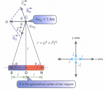
The magnetic field at C due to south pole is,
\(\vec { { B }_{ s } } =-{ B }_{ s }cos\theta \hat { i } -{ B }_{ s }sin\theta \hat { j } \) .....(2)
where Bs = \(\frac { { \mu }_{ 0 } }{ 4\pi } \frac { { q }_{ m } }{ r^{ '2 } } \)
From equations (1) and (2), the net magnetic field at point C due to dipole is \(\vec { { B } } =\vec { { B }_{ N } } +\vec { { B }_{ S } } \).
\(\vec { { B } } =-({ B }_{ N }+{ B }_{ S })cos\theta \hat { i } \) Since, BN = BS
\(\vec { { B } } =-\frac { { 2\mu }_{ 0 } }{ 4\pi } \frac { { q }_{ m } }{ r'^{ 2 } } cos\theta \hat { i } =-\frac { 2{ \mu }_{ 0 } }{ 4\pi } \frac { { q }_{ m } }{ ({ r }^{ 2 }+l^{ 2 }) } cos\theta \hat { i } \) ....(3)
In a right angle triangle NOC, as shown in the figure,
cosθ=\(\frac { adjacent }{ hypotenuse } =\frac { 1 }{ r' } =\frac { 1 }{ ({ r }^{ 2 }+{ l }^{ 2 })^{ \frac { 1 }{ 2 } } } \) .........(4)
Substituting equation (4) in equation (3) we get
\(\vec { B } =-\frac { { \mu }_{ 0 } }{ 4\pi } \frac { { q }_{ m }\times (2l) }{ ({ r }^{ 2 }+{ l }^{ 2 })^{ \frac { 3 }{ 2 } } } \hat { i } \) ........(5)
Since, magnitude of magnetic dipole moment is \(|\vec { { p }_{ m } } |\) = pm = qm. 2l and substituting in equation (5), we get the magnetic field at a point C is
\( { { \vec B }_{ equatorial } } =-\frac { { \mu }_{ 0 } }{ 4\pi } \frac { { p }_{ m } }{ ({ r }^{ 2 }+{ l }^{ 2 })^{ \frac { 3 }{ 2 } } } \hat { i } \) ........(6)
If the distance between two poles in a bar magnet are small (looks like short magnet) when compared to the distance between geometrical center O of bar magnet and the location of point C i.e., r >>l, then,
(r2 + l2)3\2 ≈ r3 ..........(7)
Therefore, using equation (7) in equation (6), we get
\( { { \vec B }_{ equatorial } } =-\frac { { \mu }_{ 0 } }{ 4\pi } \frac { { p }_{ m } }{ r^{ 3 } } \hat { i } \)
In general, the magnetic field at equatorial point is given by
\({ { \vec B }_{ equatorial } } =-\frac { { \mu }_{ 0 } }{ 4\pi } \frac { { \vec p }_{ m } }{ r^{ 3 } } \) Since pm\(\hat { i } =\vec { { p }_{ m } } \), .......(8)
29.
(i) Let 'R' be the radius of a current carrying circular loop.
(ii) I be the current flowing through the wire.
(iii) Let P be a point on the axis of the circular coil at a distance z from its centre 'O'
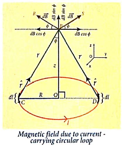
(iv) Take two diametrically opposite element \(\vec { dl } \) at C and D. According to Biot-Savart's law, the magnetic field at P due to the current element at C is
\(d \vec{B}=\frac{\mu_0}{4 \pi} \frac{I d \vec{l} \times \hat{r}}{r^2}\)
The magnitude of \( { d\vec B } \)is
\(d \vec{B}=\frac{\mu_0}{4 \pi} \frac{I d l \sin \theta}{r^2}=\frac{\mu_0}{4 \pi} \frac{I d l}{r^2}\)
where θ is the angle between \(I\vec { dl } \) and \(\vec { r } \). Here, θ = 90o.
\(\vec{B} =\int d \vec{B}=\int d B \sin \phi \hat{k} \)
\(\vec{B} =\frac{\mu_o I}{4 \pi} \int \frac{d l}{r^2} \sin \phi \hat{k} \)
\(\text {But, } \cos \theta =\frac{R}{\left(R^2+z^2\right)^{\frac{1}{2}}} \text { (using Pythagoras theorem) }\)
From ΔOCP
\(\sin \phi=\frac{R}{\left(R^2+z^2\right)^{1 / 2}} \text { and } r^2=R^2+z^2.\)
Substituting these in the above equation, we get,
\(\vec{B}=\frac{\mu_0 I}{4 \pi} \frac{R}{\left(R^2+z^2\right)^{3 / 2}} \hat{k}\left(\int d l\right)\)
If we integrate the line element from 0 to 2πR, we get the net magnetic field \(\vec{B}\) at any point P due to the current - carrying circular loop,
\(\vec{B}=\frac{\mu_0 I}{2} \frac{R^2}{\left(R^2+z^2\right)^{3 / 2}} \hat{k}\)
If the circular coil contains N turns, then the magnetic field is
\(\vec{B}=\frac{\mu_0 N I}{2} \frac{R^2}{\left(R^2+z^2\right)^{3 / 2}} \hat{k}\)
The magnetic field at the centre of the coil is,
\(\vec{B}=\frac{\mu_0NI}{2R}\hat k\) since z= 0
30.
Principle:
The principle of transformer is the mutual induction between two coils. That is, when an electric current passing through a coil changes with time, an emf is induced in the neighbouring coil.
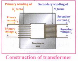
Construction:
(i) In the simple construction of transformers, there are two coils of high mutual inductance wound over the same transformer core.
(ii) The core is generally laminated and is made up of a good magnetic material like silicon steel. Coils are electrically insulated but magnetically linked via transformer core.
(iii) The coil across which alternating voltage is applied is called primary coil P and the coil from which output power is drawn out is called secondary coil S. The assembled core and coils are kept in a container which is filled with suitable medium for better insulation and cooling purpose.
Working:
(i) If the primary coil is connected to a source of alternating voltage, an alternating magnetic flux is set up in the laminated core.
(ii) If there is no magnetic flux leakage, then whole of magnetic flux linked with primary coil is also linked with secondary coil.
(iii) This means that rate at which magnetic flux changes through each turn is same for both primary and secondary coils.
(iv) As a result of flux change, emf is induced in both primary and secondary coils. The emf induced in the primary coil vp or back of εp is given by,
vp = εp = -Np \(\frac{dФ_B}{dt}\) ........(1)
(vi) The frequency of alternating magnetic flux in the core is same as the frequency of the applied voltage. Therefore, induced emf in secondary will also have same frequency as that of applied voltage. The emf induced in the secondary coil εs is given by ,
εs = -Ns\(\frac{dФ_B}{dt}\)
Where Np and Ns are the number of turns in the primary and secondary coil respectively. If the secondary circuit is open, then εs = ሀs where u is the voltage ሀs across secondary coil
ሀs = εs = -Ns \(\frac{dФ_B}{dt}\) ........(2)
From equations (1) and (2),
\(\frac{v_s}{v_p}=\frac{N_s}{N_p}\) = K ........(3)
(vii) This constant K is known as voltage transformation ratio. For an ideal transformer, input power vpip= Output power vsis
where ip and is are the currents in the primary and secondary coil respectively.
(ix) Therefore,
\(\frac{V_s}{V_p}=\frac{N_s}{N_p}=\frac{I_p}{I_s}\) ........(4)
Equation (4) is written in terms of amplitude of corresponding quantities
\(\frac{V_s}{V_p}=\frac{N_s}{N_p}=\frac{I_p}{I_s}\) = K
i) If Ns> Np (or K > 1), ∴ Vs > Vp and Is < Ip This is the case of step-up transformer in which voltage is increased and the corresponding current is decreased.
ii) If Ns< Np (or K < 1), ∴ Vs < Vp and Is > Ip This is step-down transformer where voltage is decreased and the current is increased.
Efficiency of a transformer:
The efficiency η of a transformer is defined as the ratio of the useful output power to the input power. Thus,
\(η=\frac{Outpur \ power}{Input \ power}\times100% \) % ....(5)
31.
Emission spectra:
When the spectrum of self luminous source is taken, we get emission spectrum. Each source has its own characteristic emission spectrum. The emission spectrum can be divided into three types:
(i) Continuous emission spectra (or continuous spectra) :
(a) If the light from incandescent lamp (filament bulb) is allowed to pass through prism (simplest spectroscope), it splits into seven colours.
(b) Thus, it consists of wavelengths containing all the visible colours ranging from violet to red (in the figure). Examples: spectrum obtained from carbon arc, incandescent solids.
(ii) Line emission spectrum (or line spectrum) :
(a) Suppose light from hot gas is allowed to pass through a prism, line spectrum is observed. Line spectra are also known as discontinuous spectra. The line spectra consists of sharp lines of definite wavelengths or frequencies.
(b) Such spectra arise due to excited atoms of elements. These lines are the characteristics of the element and are different for different elements. Examples: spectra of atomic hydrogen, helium, etc.
(iii) Band emission spectrum (or band spectrum) :
(a) Band spectrum consists of several number of very closely spaced spectral lines which overlapped together forming specific bands which are separated by dark spaces.
(b) This spectrum has a sharp edge at one end and fades out at the other end. Such spectra arise when the molecules are excited.
(c) Band spectrum is the characteristic of the molecule hence, the structure of the molecules can be studied using their band spectra. Examples, spectra of hydrogen gas, ammonia gas in the discharge tube, etc.
32.
(a) Capacitor in series
(i) Consider three capacitors of capacitance C1, C2 and C3 connected in series with a battery of voltage V as shown in the Figure (a).
(ii) As soon as the battery is connected to the capacitors in series, the electrons of charge -Q are transferred from negative terminal to the right plate of C3 which pushes the electrons of same amount -Q from left plate of C3 to the right plate of C2 due to electrostatic induction.
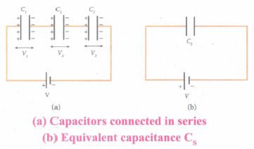
(iii) Similarly, the left plate of C2 pushes the charges of -Q to the right plate of C1 which induces the positive charge +Q on the left plate of C1.
(iv) At the same time, electrons of charge -Q are transferred from left plate of C1 to positive terminal of the battery.
(v) By these processes, each capacitor stores the same amount of charge Q.
(vi) The capacitances of the capacitors are in general different so that the voltage across each capacitor is also different and are denoted as V1, V2 and V3 respectively.
(vii) The sum voltage across capacitor must be equal to the voltage of the battery.
V = V1 + V2 + V3 ....(1)
Since, Q = CV
We have V = \(\frac { Q }{ { C }_{ 1 } } +\frac { Q }{ { C }_{ 2 } } +\frac { Q }{ { C }_{ 3 } } \)
\(=Q\left[ \frac { 1 }{ { C }_{ 1 } } +\frac { 1 }{ { C }_{ 2 } } +\frac { 1 }{ { C }_{ 3 } } \right] ...(2)\)
(viii) If three capacitors in series are considered to form an equivalent single capacitor Cs shown in Figure (b), then we have \(V=\frac { Q }{ { C }_{ s } } \). Substituting this expression into equation (2), we get
\(\frac { Q }{ { C }_{ s } } =Q\left( \frac { 1 }{ { C }_{ 1 } } +\frac { 1 }{ { C }_{ 2 } } +\frac { 1 }{ { C }_{ 3 } } \right) \)
\(\frac { 1 }{ { C }_{ s } } =\frac { 1 }{ { C }_{ 1 } } +\frac { 1 }{ { C }_{ 2 } } +\frac { 1 }{ { C }_{ 3 } } \) ...(3)
(ix) Thus, the inverse of the equivalent capacitance Cs of three capacitors connected in series is equal to the sum of the inverses of each capacitance. This equivalent capacitance Cs, is always less than the smallest individual capacitance in the series.
(b) Capacitor in parallel
i) Consider three capacitors of capacitance C1, C2 and C3 connected in parallel with a battery of voltage V as shown in Figure (a).
ii) Since corresponding sides of the capacitors are connected to the same positive and negative terminals of the battery, the voltage across each capacitor is equal to the battery's voltage.
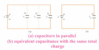
iii) Since capacitance of the capacitors is different, the charge stored in each capacitor is not the same. Let the charge stored in the three capacitors be Q1, Q2, and Q3 respectively.
iv) According to the law of conservation of total charge, the sum of these three charges is equal to the charge Q transferred by the battery,
Q = Q1 + Q2 + Q3 ...(4)
Now, since Q = CV, we have
Q = C1V + C2V + C3V ...(5)
(v) If these three capacitors are considered to form a single capacitance C, which stores the total charge Q as shown in the Figure (b), then we can write Q = CpV. Substituting this in equation (2), we get
CpV = C1V + C2V + C3V
Cp = C1+ C2 + C3 ...(6)
vi) Thus, the equivalent capacitance of capacitors connected in parallel is equal to the sum of the individual capacitances.
vii) The equivalent capacitance Cp, in a parallel connection is always greater than the largest individual capacitance. In a parallel connection, it is equivalent as area of each capacitance adds to give more effective area such that total capacitance increases.
33.
Electric field due to charged infinite plane sheet:
(i) Consider an infinite plane sheet of charges with uniform surface charge density σ. (Charge per unit area). Let P be a point at a distance of r from the sheet as shown in the Figure.
(ii) Since the plane is infinitely large, the electric field should be same at all points equidistant from the plane and radially directed outward at all points. A cylindrical-shaped Gaussian surface of length 2r and two flat surfaces is chosen such that the infinite plane sheet passes perpendicularly through the middle part of the Gaussian surface.
Total electric flux linked with the cylindrical surface,
\({ \phi }_{ E }=\int { \vec { E } .d\vec { A } } \)
\(=\int _{ Curved\ surface }^{ }{ \vec { E } .d\vec { A } } +\int _{ P }^{ }{ \vec { E } .d\vec { A } + } \int _{ P^{'} }^{ }{ \vec { E } .d\vec { A } } =\frac { { Q }_{ encl } }{ { \varepsilon }_{ 0 } } \quad ...(1)\)
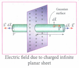
(iii) The electric field is perpendicular to the area element at all points on the curved surface and is parallel to the surface areas at P and P ' (Figure). Then, applying Gauss's law.
\({ \phi }_{ E }=\int _{ p }^{ }{ EdA+ } \int _{ p' }^{ }{ EdA= } \frac { { Q }_{ encl } }{ { \varepsilon }_{ 0 } } \quad ...(2)\)
Since the magnitude of the electric field at these two equal flat surfaces is uniform, E is taken out of the integration and Qncel is given by Qencl = σA, we get
\(2E\int _{ p }^{ }{ dA=\frac { \sigma A }{ { \varepsilon }_{ 0 } } } \)
The total area of surface either at P or P'
\(\int _{ p }^{ }{ dA=A } \)
Hence \(2EA=\frac { \sigma A }{ { \varepsilon }_{ 0 } }\) or \(E=\frac { \sigma }{ 2{ \varepsilon }_{ 0 } } \quad \quad \quad \quad ...(3)\)
In vector \(\vec { E } =\frac { \sigma }{ 2{ \varepsilon }_{ 0 } } \hat { n } \quad \quad \quad \quad ...(4)\)
(iv) Here \(\hat { n } \) is the outward unit vector normal to the plane. Note that the electric field due to an infinite plane sheet of charge depends on the surface charge density and is independent of the distance r.
(v) The electric field will be the same at any point farther away from the charged plane.
(vi) Equation (4) implies that if σ > 0 the electric field at any point P is outward perpendicular \(\hat { n } \) to the plane and if σ < 0 the electric field points inward perpendicularly (\(-\hat { n } \)) to the plane.
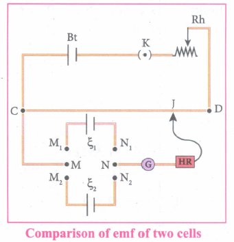
34.
35.
(i) Stretch out forefinger, the middle finger and the thumb of the left hand such that they are in three mutually perpendicular directions.
(ii) If the forefinger points in the direction of magnetic field, the middle finger in the direction of the electric current, then thumb will point in the direction of the force experienced by the conductor.
36.
According to Huygens's principle, each point of the wavefront is the source of secondary wavelets emanating from these points spreading out in all directions with the speed of the wave. These are called as secondary wavelets.
37.
Dispersion is splitting of white light into its constituent colours. This band of Colours of light is called its spectrum.
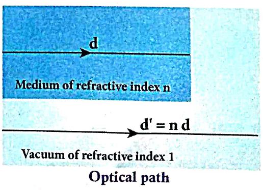
38.
39.
Coulomb's inverse square law states that the force of attraction or repulsion between two magnetic poles is directly proportional to the product of their pole strengths and inversely proportional to the square of the distance between them.
\(\vec { F } =k \frac { { q }_{ m_{A} }{ q }_{ m_{B} } }{ { r }^{ 2 } } \hat { r } \)
40.
41.
The displacement current can be defined as the current which comes into play in the region in which the electric field or the electric flux is changing with time.
42.
The capacitance C of a capacitor is defined as the ratio of the magnitude of charge on either of the conductor plates to the potential difference existing between the conductors. \(C=\frac{Q}{V}\)
Its unit is Coulomb per volt or farad (F).
43.

12th Standard Syllabus & Materials
12th Standard
TN 12th Computer Applications களப்பெயர் முறைமை (DNS) Sample Question Papers Study Material - QB365 Set A
NEW12th Standard
TN 12th Computer Applications வலையமைப்பு எடுத்துக்காட்டுகள் மற்றும் நெறிமுறைகள் Sample Question Papers Study Material - QB365 Set A
NEW12th Standard
TN 12th Computer Applications கணினி வலையமைப்பு ஓர் அறிமுகம் Sample Question Papers Study Material - QB365 Set A
NEW12th Standard
TN 12th Computer Applications PHP-உடன் MySQL-ஐ இணைத்தல் Sample Question Papers Study Material - QB365 Set A



Tamilnadu Stateboard 12th Standard Subjects

Maths

Chemistry
Physics

Biology

Computer Science

Business Maths and Statistics

Economics

Commerce

Accountancy

History

Computer Applications
Biology
Computer Technology
Computer Applications
Computer Science
Business Maths and Statistics
Commerce
Economics
Maths
Chemistry
Physics
Computer Technology
History
Accountancy

Tamil

English

French
Tamilnadu Stateboard Standards


