
 100% FREE ACCESS
12th Standard Syllabus & Materials
12th Standard
TN 12th Maths Applications of Matrices and Determinants Sample Question Papers Study Material - QB365 Set A
NEW12th Standard
TN 12th Computer Applications மின்னணு தரவு பரிமாற்றம் Sample Question Papers Study Material - QB365 Set A
NEW12th Standard
TN 12th Computer Applications மின் - வணிக பாதுகாப்பு அமைப்புகள் Sample Question Papers Study Material - QB365 Set A
NEW12th Standard
TN 12th Computer Applications மின்னணு செலுத்தல் முறைகள் Sample Question Papers Study Material - QB365 Set A
NEW12th Standard
TN 12th Computer Applications மின் - வணிகம் Sample Question Papers Study Material - QB365 Set A
NEW12th Standard
TN 12th Computer Applications திறந்த மூல கருத்துருக்கள் Sample Question Papers Study Material - QB365 Set A

Published on: 28/11/2025
Download Tamil Nadu 12th Standard Physics question papers, model tests, one-mark questions, important questions, and public exam papers in PDF format. Free study materials and answer keys for TN State Board students.
Questions + Answers key
Take MCQ Physics Test
1.
Why can’t we interchange the emitter and collector even though they are made up of the same type of semiconductor material?
2.
A convex lens forms the image of the sun at a distance of 10 cm. Where will be the image when
(i) another lens of the same power but double the aperture is used.
(ii) Another lens of the same aperture but double the power is used?
3.
When does power factor of a series RLC circuit become maximum?
4.
What is meant by Fraunhofer lines?
5.
Using the relation \(\overset { \rightarrow }{ B } =\mu _{ ° }(\overset { \rightarrow }{ H+ } \overset { \rightarrow }{ M } )\) show that \({ x }_{ m }={ \mu }_{ r }-{ 1 }\)
6.
Charging current for a capacitor is 0.2 A, find the displacement current.
zero
0.2 A
0.4 A
0.1 A
7.
In an experiment of finding the focal length of a concave mirror, a graph is drawn between the magnitudes of u and V. the graph looks like _____________.
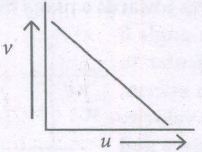
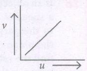
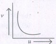
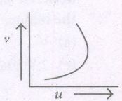
8.
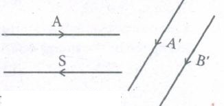
The figure shows two rays A and B being reflected by a mirror and going as 'A' and 'B' the mirror is ____________.
plane
concave
convex
may be any spherical mirror
9.
The given electrical network is equivalent to ______.

AND gate
OR gate
NOR gate
NOT gate
10.
A ray of light travelling in a transparent medium of refractive index n falls, on a surface separating the medium from air at an angle of incidents of 45o . The ray can undergo total internal reflection for the following n, ______.
n = 1.25
n = 1.33
n = 1.4
n = 1.5
11.
The wavelength range of x-rays is _________ (m).
10-4 to 10-2
10-14 to 10-9
10-10 to 3 X 10⁻⁸
10-3 to 10-5
12.
A wire of length l carrying a current I along the Y direction is kept in a magnetic field is given by \(\vec { B } =\frac { \beta }{ \sqrt { 3 } } =(\hat { i } +\hat { j } +\hat { k } )T.\) The magnitude of Lorentz force acting on the wire is _____.
\(\sqrt { \frac { 2 }{ { 3 } } } \beta Il\)
\(\sqrt { \frac { 1 }{ { 3 } } } \beta Il\)
\(\sqrt { 2 } \beta Il\)
\(\sqrt { \frac { 1 }{ 2 } } \beta Il\)
13.
In a series resonant RLC circuit, the voltage across 100 Ω resistor is 40 V. The resonant frequency ω is 250 rad/s. If the value of C is 4 µF, then the voltage across L is
600 V
4000 V
400 V
1 V
14.
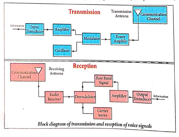
Explain the basic elements of communication system with the necessary block diagram.
15.
Explain the working of a single-phase AC generator with necessary diagram.
16.
Discuss the Hertz experiment.
17.
Explain why TV transmission towers made high.
18.
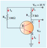
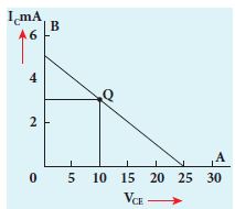
The current gain of a common emitter transistor circuit shown in figure is 120. Draw the DC load line and mark the Q point on it. (VBE to be ignored).
19.
A coil of 200 turns carries a current of 0.4 A. If the magnetic flux of 4 mWb is linked with each turn of the coil, find the inductance of the coil.
1.
Because of the differing size and the amount of doping, the emitter and collector cannot be interchanged.
2.
(i) Since aperture does not affect f therefore the image would still be formed at a distance of 10 cm.
(ii) When power is doubled, focal length is halved. So, image would be formed at a distance of 5 cm.
3.
Power factor will be maximum, when Φ = 0 i.e., \(\tan ^{-1}\left(\frac{X_L-X_C}{R}\right)=0\)
\(\therefore X_L=X_C \Rightarrow L \omega=\frac{1}{C \omega} \)
\(\therefore \omega=\frac{1}{2 \pi \sqrt{L C}}\)
∴ Current I be max \(I_m=\frac{V_m}{R}\)
Hence power factor of a RLC series circuit becomes maximum, when
(i) \(X_L=X_C\)
(ii) Current \(I_m=\frac{V_m}{R}\) will be maximum
(iii) Frequency \(\omega_r=\frac{1}{2 \pi \sqrt{L C}}\)
4.
When the spectrum obtained from the Sun is examined, it consists of large number of dark lines (line absorption spectrum). These dark lines in the solar spectrum are known as Fraunhofer lines.
5.
\(\overset { \rightarrow }{ B } =\mu _{ ° }(\overset { \rightarrow }{ H+ } \overset { \rightarrow }{ M } )\)
But from equation (3.33), in vector form,
\(\overset { \rightarrow }{ M } ={ x }_{ m }\overset { \rightarrow }{ H } \)
Hence, \(\overset { \rightarrow }{ B } =\mu _{ ° }({ x }_{ m }+1)\overset { \rightarrow }{ H } \Rightarrow \overset { \rightarrow }{ B } =\mu \overset { \rightarrow }{ H } \)
where, \(\mu =\mu _{ ° }({ x }_{ m }+1)\Rightarrow { x }_{ m }+1=\frac { \mu }{ \mu _{ ° } } =\mu _{ r }\)
\(\Rightarrow { x }_{ m }=\mu _{ r }-1\)
6.
Id=I= 0.2 A
7.
(c)
8.
(a)
plane
9.
\(Y_1=\overline{A+B}, y_2=\overline{A+B}=A+B, y=\overline{A+B}\)
10.
For total internal reflection,
sin i > sin c
\(n=\frac{1}{sin \ c}\)
\(sin \ c=\frac{1}{n}\)
\(sin \ i>\frac{1}{n}\)
\(n>\frac{1}{sin \ i}\)
n >\(\sqrt{2}\)
n >1.414 = 1.5
11.
(c)
10-10 to 3 X 10⁻⁸
12.
\(\vec { B } =\frac { \beta }{ \sqrt { 3 } } =(\hat { i } +\hat { j } +\hat { k } )T\)
Using an equation,
Lorentz force, \(\vec{F}=Il\hat{j}\times\vec B\)
We can get,
Lorentz force \(F=\sqrt { \frac { 2 }{ { 3 } } } \beta Il\)
13.
\(\omega=250 \mathrm{rad} / \mathrm{s}, C=4 \times 10^{-} \mathrm{F} \)
\(R=100 \Omega, \quad \mathrm{V}_{\mathrm{R}}=40 \mathrm{~V} \)
\(\therefore I_{\mathrm{R}}=\frac{V_R}{100}=\frac{40}{100}=0.4 \mathrm{~A} \)
\(\omega=\frac{1}{\sqrt{L C}} \)
\(\omega^2=\frac{1}{L C} \)
\((250)^2=\frac{1}{L \times 4 \times 10^{-6}} \)
\(L=\frac{1}{4 \times(250)^2 \times 10^{-6}} \)
\(=\frac{1}{4 \times 250 \times 250 \times 10^{-6}} \)
\(=\frac{1}{1000 \times 10^{-6} \times 250} \)
\(=\frac{10^3}{250}=\frac{1000}{250}=4 \mathrm{H}\)
Voltage acnoss L, Vt = IXL
VL = l x L x ω
= 0.4 x 4 x 250
0.4 x 1000 = 400 V
14.
a) Information (Baseband or input signal):
i) Information can be in the form of a sound signal like speech, music, pictures, or computer data which is given as input to the input transducer.
b) Input transducer:
i) It converts the information which is in the form of sound, music, pictures or computer data into corresponding electrical signals.
ii) The electrical equivalent of the original information is called the baseband signal.
iii) The best example is the microphone that converts sound energy into electrical energy.
c) Transmitter
i) It feeds the electrical signal from the transducer to the communication channel
ii) It consists of circuits such as amplifier, oscillator, modulator, and power amplifier.
iii) Amplifier: The transducer output is very weak and is amplified by the amplifier.
iv) Oscillator: It generates high-frequency carrier wave (a sinusoidal wave) for long distance transmission into space. As the energy of a wave is proportional to its frequency, the carrier wave has very high energy.
v) Modulator: It superimposes the baseband signal onto the carrier signal and generates the modulated signal.
vi) Power amplifier: It increases the power level of the electrical signal in order to cover a large distance.
d) Transmitting antenna:
i) It radiates the radio signal into space in all directions.
ii) It travels in the form of electromagnetic waves with the speed of light.
e) Communication channel:
Communication channel is used to carry the electrical signal from transmitter to receiver with less noise or distortion.
Example: Wires, cables, optical fibres in wireline communication and free space in wireless communication.
f) Receiver:
i) The signals that are transmitted through the communication medium are received with the help of a receiving antenna and are fed into the receiver.
ii) The receiver consists of electronic circuits like demodulator, amplifier, detector etc. The demodulator extracts the baseband signal from the carrier signal.
iii) Then the baseband signal is detected and amplified using amplifiers.
iv) Finally, it is fed to the output transducer.
g) Repeaters:
i) Repeaters are used to increase the range or distance through which the signals are sent.
ii) It is a combination of transmitter and receiver.
iii) The signals are received, amplified, and retransmitted with a carrier signal of different frequency to the destination.
iv) The best example is the communication satellite in space
h) Output transducer:
i) It converts the electrical signal back to its original form such as sound, music, pictures or data.
ii) Examples of output transducers are loudspeakers, picture tubes, computer monitor, etc
15.
.JPG)
Working: The loop PQRS is stationary and is perpendicular to the plane of the paper. When field windings are excited, magnetic field is produced around it. Let the field magnet be rotated in clockwise direction by some external means (Figure).
(i) Assume that initial position of the field magnet is horizontal. At that instant, the direction of magnetic field is perpendicular to the plane of the loop PQRS. The induced emf is zero. This is represented by origin O in the graph between induced emf and time angle.
(ii) When field magnet rotates through 90°, magnetic field becomes parallel to PQRS. The induced emfs across PQ and RS would become maximum. Since they are connected in series, emfs are added up and the direction of total induced emf is given by Flemin's right hand rule.
.JPG)
(iii) Care has to be taken while applying this rule, the thumb indicates the direction of the motion of the conductor with respect to field. For clockwise rotating poles, the conductor appears to be rotating anticlockwise. Hence, thumb should point to the left. The direction of the induced emf is at right angles to the plane of the paper. For PQ, it is inwards and for RS outwards. Therefore, the current flows along PQRS. The point A in the graph represents this maximum emf.
(iv) For the rotation of 180° from the initial position, the field is again perpendicular to PQRS and the induced emf becomes zero. This is represented by point B.
(v) The field magnet becomes again parallel to PQRS for 270° rotation of field magnet. The induced emf is maximum but the direction is reversed. Thus the current flows along SRQP. This is represented by point C
(vi) On completion of 360°, the induced emf becomes zero and is represented by the point D. From the graph, it is clear that emf induced in PQRS is alternating in nature.
(vii) Therefore, when field magnet completes one rotation, induced emf in PQRS finishes one cycle.
16.
(i) The experimental set up it consists of two metal electrodes which are made of small spherical metals. These are connected to larger spheres and the ends of them are connected to induction coil with very large number of turns.
(ii) This is to produce very high electromotive force (emf). Since the coil is maintained at very high potential, air between the electrodes gets ionized and spark (spark means discharge of electricity) is produced.
(iii) This discharge of electricity affects another electrode (ring type - not completely closed) which is kept at far distance. This implies that the energy is transmitted from electrode to the receiver (ring electrode) in the form of waves, known as electromagnetic waves. If the receiver is rotated by 90o then no spark is observed by the receiver.
(iv) This confirms that electromagnetic waves are transverse waves as predicted by Maxwell. Hertz detected radio waves and also computed the speed of radio waves which is equal to the speed of light (3 x 10⁸ ms-1).
17.
i) The TV signals are frequency modulated. The transmission of TV signals cannot be obtained the ground wave propagation, as such signals get absorbed by ground due to their high frequency.
ii) TV signals cannot be transmitted via skywave propagation as the ionosphere is unable to reflect radio waves of frequencies greater than 40 MHz.
iii) Therefore, the only way out for the transmission of TV signals is that receiving antenna should directly intercept the signal from the transmitting antenna.
18.
β = 120
Base current, \({ I }_{ B }=\frac { 25V }{ 1M\Omega } =\frac { 25 }{ 1\times { 10 }^{ 6 } } =25\mu A\)
We know that
\(\beta =\frac { { I }_{ C } }{ { I }_{ B } } \) (or)
IC = β IB = 120 x 25 μA
= 3000 μA = 3 mA
VCE = VCC - ICRC
= 25 - (3 mA x 5k) = 10 V
19.
Current, I = 0.4 A, Magnetic flux, Φ = 4 x 10⁻³ Wb, Number of turns, N = 200
Inductance, L = \(\frac { N\Phi }{ I }\)
\(L=\frac { 200\times 4\times 10^{ -3 } }{ 0.4 } =200 \times10^{-3+1}\)
= 200 x 10-2 = 2H.
∴ Inductance of the coil = 2 H.

12th Standard Syllabus & Materials
12th Standard
TN 12th Computer Applications வலையமைப்பு வடமிடல் Sample Question Papers Study Material - QB365 Set A
NEW12th Standard
TN 12th Computer Applications களப்பெயர் முறைமை (DNS) Sample Question Papers Study Material - QB365 Set A
NEW12th Standard
TN 12th Computer Applications வலையமைப்பு எடுத்துக்காட்டுகள் மற்றும் நெறிமுறைகள் Sample Question Papers Study Material - QB365 Set A
NEW12th Standard
TN 12th Computer Applications கணினி வலையமைப்பு ஓர் அறிமுகம் Sample Question Papers Study Material - QB365 Set A



Tamilnadu Stateboard 12th Standard Subjects

Maths

Chemistry
Physics

Biology

Computer Science

Business Maths and Statistics

Economics

Commerce

Accountancy

History

Computer Applications
Biology
Computer Technology
Computer Applications
Computer Science
Business Maths and Statistics
Commerce
Economics
Maths
Chemistry
Physics
Computer Technology
History
Accountancy

Tamil

English

French
Tamilnadu Stateboard Standards


