
12th Standard Syllabus & Materials
12th Standard
TN 12th Computer Applications மின்னணு தரவு பரிமாற்றம் Sample Question Papers Study Material - QB365 Set A
NEW12th Standard
TN 12th Computer Applications மின் - வணிக பாதுகாப்பு அமைப்புகள் Sample Question Papers Study Material - QB365 Set A
NEW12th Standard
TN 12th Computer Applications மின்னணு செலுத்தல் முறைகள் Sample Question Papers Study Material - QB365 Set A
NEW12th Standard
TN 12th Computer Applications மின் - வணிகம் Sample Question Papers Study Material - QB365 Set A
NEW12th Standard
TN 12th Computer Applications திறந்த மூல கருத்துருக்கள் Sample Question Papers Study Material - QB365 Set A
NEW12th Standard
TN 12th Computer Applications வலையமைப்பு வடமிடல் Sample Question Papers Study Material - QB365 Set A

Published on: 22/08/2026
Download Tamil Nadu 12th Standard Physics question papers, model tests, one-mark questions, important questions, and public exam papers in PDF format. Free study materials and answer keys for TN State Board students.
Questions + Answers key
Take MCQ Physics Test
1.
Why are e.m. waves non-mechanical?
2.
Give two uses each of
(i) IR radiation,
(ii) Microwaves and
(iii) UV radiation.
3.
How will you define Q-factor?
4.
How will you define RMS value of an alternating current?
5.
Give the principle of AC generator.
6.
What are electromagnetic waves?
7.
What is displacement current?
8.
The relative magnetic permeability of the medium is 2.5 and the relative electrical permittivity of the medium is 2.25. Compute the refractive index of the medium.
9.
What are Fraunhofer lines? How are they useful in the identification of elements present in the Sun?
10.
Discuss the Hertz experiment.
11.
Mention the various energy losses in a transformer.
12.
13.
Write short notes on
(a) microwaves
(b) X - rays
(c) Radio waves
(d) Visible spectrum
14.
Let an electromagnetic wave propagate along the x-direction, the magnetic field oscillates at a frequency of 1010 Hz and has an amplitude of 10−5 T, acting along the y-direction. Then, compute the wavelength of the wave. Also write down the expression for electric field in this case.
15.
A series RLC circuit which resonates at 400 kHz has 80 μH inductors, 2000 pF capacitor and 50 Ω resistor. Calculate
(i) Q-factor of the circuit
(ii) the new value of capacitance when the value of inductance is doubled and
(iii) the new Q-factor.
16.
A magnetron in a microwave oven emits electromagnetic waves (em waves) with frequency f = 2450 MHz. What magnetic field strength is required for electrons to move in circular paths with this frequency?
17.
Obtain an expression for average power of AC over a cycle. Discuss its special cases.
18.
Derive an expression for phase angle between the applied voltage and current in a series RLC circuit.
19.
Find out the phase relationship between voltage and current in a pure inductive circuit.
20.
21.
Explain the Maxwell’s modification of Ampere’s circuital law.
22.
Write down Maxwell equations in integral form.
1.
Electromagnetic waves are produced by the accelerated charges not by the mechanical vibrations of particles. It travels with speed equals to the speed of light in vacuum.
2.
(i) IR radiation:
(i) It is used to produce dehydrated fruits, in green houses to keep the plants warm, heat therapy for muscular pain or sprain, TV remote as a signal carrier, to look through haze fog or mist.
(ii) It is used in night vision or infrared photography.
(ii) Microwaves:
It is used in radar systems for aircraft navigation, speed of the vehicle microwave oven for cooking and very long distance wireless communication through satellites.
(iii) UV radiation:
It is used to destroy bacteria in sterilizing the surgical instruments, burglar alarms, to detect the invisible writing, finger prints and also in the study of atomic structure.
3.
Q factor is defined as the ratio of voltage across L or C to resonance to the applied voltage
Q - factor = \(\frac{Voltage \ across \ L \ or \ C \ resonance }{Applied \ voltage}\)
\(Q-factor=\frac{X_{L}}{R}=\frac{1}{R}\sqrt\frac{{L}}{C}\)
4.
RMS value is also defined as that value of the steady current which when flowing through a given circuit for a given time produces the same amount of heat as produced by the alternating current when flowing through the same Circuit for the same time. (or)
The root mean square value of an alternating current is defined as the square root of the mean of the squares of all currents over one cycle
\(I_{RMS}=\sqrt\frac{\text {Area of one cycle of squared wave}}{\text {Base length of one cycle}}\)
5.
AC generator work on the principle of electromagnetic induction. The relative motion between a conductor and a magnetic field changes the magnetic flux linked with the conductor which in turn, induces an emf
6.
An electromagnetic waves are the waves that are radiated by an accelerated charge which propagates through space as coupled electric and magnetic fields, oscillating perpendicular to each other and to the direction of propagation of the wave.
7.
The displacement current can be defined as the current which comes into play in the region in which the electric field or the electric flux is changing with time.
8.
Dielectric constant (relative permittivity of the medium) is εr = 2.25
Magnetic permeability is μr = 2.5
Refractive index of the medium,
n = \(\sqrt { { \varepsilon }_{ r }{ \mu }_{ r } } =\sqrt { 2.25\times 2.5 } \) = 2.37
9.
(i) When the spectrum obtained from the Sun is examined, it consists of large number of dark lines . These dark lines in the solar spectrum are called Fraunhofer lines.
(ii) The Absorption spectra for various materials are compared with the Fraunhofer lines in the solar spectrum, which helps in identifying elements present in the Sun's atmosphere.
10.
(i) The experimental set up it consists of two metal electrodes which are made of small spherical metals. These are connected to larger spheres and the ends of them are connected to induction coil with very large number of turns.
(ii) This is to produce very high electromotive force (emf). Since the coil is maintained at very high potential, air between the electrodes gets ionized and spark (spark means discharge of electricity) is produced.
(iii) This discharge of electricity affects another electrode (ring type - not completely closed) which is kept at far distance. This implies that the energy is transmitted from electrode to the receiver (ring electrode) in the form of waves, known as electromagnetic waves. If the receiver is rotated by 90o then no spark is observed by the receiver.
(iv) This confirms that electromagnetic waves are transverse waves as predicted by Maxwell. Hertz detected radio waves and also computed the speed of radio waves which is equal to the speed of light (3 x 10⁸ ms-1).
11.
| S.No | Name of the losses | Source of losses | Method to minimise |
| (i) | (a) Core loss (or) Iron loss (or) Hysteresis loss | Transformer core is magnetised and demagnetised repeatedly |
Using steel of high silicon content in making transformer core |
| (b) Eddy current loss | Alternating magnetic flux in the core induces eddy currents in it. |
Using very thin laminations of transformer core. | |
| (ii) | Copper loss | When the electric current flows through windings of transformers, some amount of energy is dissipated due to Joule heating |
Using wires of larger diameter |
| (iii) | Flux leakage | The magnetic lines of primary coil are not completely linked with secondary coil. |
Windings the coils one over the other. |
12.
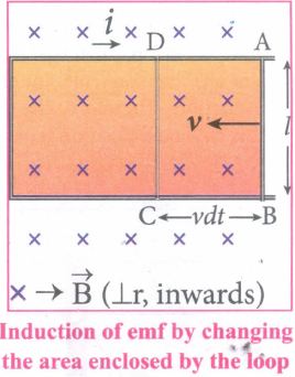
13.
(a) Microwaves:
It is produced by special vacuum tubes such as klystron, magnetron and gunn diode. The frequency range of microwaves is 109 Hz to 1011 Hz. These waves undergo reflection and can be polarised.
Uses:
It is used in radar system for aircraft navigation, speed of the vehicle, microwave oven for cooking and very long distance wireless communication through satellites.
(b) X-rays:
lt is produced when there is sudden stopping of high speed electrons at high-atomic number target, and also by electronic transitions among the innermost orbits of atoms. The frequency range of X-rays is from 1017 Hz to 1019 Hz. X-rays have more penetrating power than ultraviolet radiation.
Uses:
X-rays are used extensively in studying structures of inner atomic electron shells and crystal structures. It is used in detecting fractures, diseased organs, formation of bones and stones, observing the progress of healing bones. Further, in a finished metal product, it is used to detect faults, cracks, flaws and holes.
(c) Radio waves:
It is produced by accelerated motion of charges in conducting wires. The frequency range is from few Hz to 109 Hz. It obeys reflection and diffraction.
Uses:
It is uses in radio and television communication systems and also in cellular phones to transmit voice communication in the ultra high frequency band.
(d) Visible light:
Visible light is produced by incandescent bodies and also it is radiated by excited atoms in gases. The frequency range is from 4 x 10¹⁴ Hz to 8 x 10¹⁴ Hz. It obeys the laws of interference, diffraction and can be polarised. It exhibits photo-electric effect also.
Uses:
It can be used to study the structure of molecules, arrangement of electrons in external shells of atoms and it causes sensation of vision.
14.
Amplitude of magnetic field B = 10-5 T
Frequency, f = 1010 HZ
(i) Wavelength of the wave,
\({\lambda}=\frac{c}{f} =\frac{3 \times 10^8}{ 10^{10}} \)
= 3 x 10⁸ - 10
Wavelength = 3 x 10⁻² m
(ii) Electric field E(x,t)\(\hat i\)
Angular frequency \(\omega =2 \pi f \)
\(\omega=2 \times 3.14 \times 10^{10}=6.28 \times 10^{10} rads^{-1}\)
\(k=\frac{2 \pi}{\lambda} =\frac{2 \times 3.14}{3 \times 10^{-2}} \)
\(=\frac{6.28}{3 \times 10^{-2}}=\frac{628}{3}=2.09 \times 10^{2} \)
k = 2.09 x 10²
(iii) Eo = BoC
Eo = 10-5 x 3 x 108
Eo = 3 x 10³ V m-1
The required expression for electric field is
\(\vec{E}(x, t)=E_o \sin \left(\frac{2 \pi}{\lambda} x-2 \pi f t\right) \hat{i} N C^{-1} \)
\(\vec{E}(x , t)=3 \times 10^{3} \sin \left(2.09 \times 10^{2} \mathrm{x}-6.28 \times 10^{10} \mathrm{t}\right) \hat(-{k}) N C^{-1} \)
15.
L = 80 x 10-6H; C = 2000 x 10-12 F
R = 50 Ω; fr = 400 x 103Hz
(i) Q-factor, \(Q_1=\frac { 1 }{ R } \sqrt { \frac { L }{ C } } \)
=\(\frac { 1 }{ 50 } \sqrt { \frac { 80\times { 10 }^{ -6 } }{ 200\times 10^{ -12 } } } \)=4
(ii) When L2 = 2 L
= 2 x 80 x 10-6 H
= 160 x 10-6 H,
C2 = \(\frac { 1 }{ 4{ \pi }^{ 2 }{ f }_{ r }^{ 2 }{ L }_{ 2 } } \)
=\(\frac { 1 }{ 4\times 3.14^{ 2 }\times (400\times 10^{ 3 })^2\times 160\times 10^{ -6 } } \)
\(\simeq \) 1000 x 10-12 F
C2 = 1000 pF
(iii) Q2 = \(\frac { 1 }{ R } \sqrt { \frac { { L }_{ 2 } }{ { C }_{ 2 } } } =\frac { 1 }{ 50 } \sqrt { \frac { 160\times 10^{ -6 } }{ 1000\times 10^{ -12 } } } \)
= \(\frac { 1 }{ 50 } \sqrt { \frac { 16\times { 10 }^{ -5 } }{ { 10 }^{ -9 } } } =\frac { 4\times { 10 }^{ 2 } }{ 50 } \) = 8
16.
Frequency of the electromagnetic waves given, f = 2450 MHz
The corresponding angular frequency is
ω = 2πf = 2 x 3.14 x 2450 x 106
= 15,386 x 106 Hz
= 1.54 x 10¹⁰ s-1
The required magnetic field, B = \(\frac { { m }_{ e }\omega }{ |q| } \)
Mass of the electron, me = 9.11 x 10⁻³¹ kg
Charge of the electron,
q = -1.60 x 10⁻¹⁹C
⇒ |q| = 1.60 x 10⁻¹⁹ C
B = \(\frac { (9.11\times { 10 }^{ -31 })(1.54\times 10^{ 10 }) }{ (1.60\times 10^{ -19 }) } \) = 8.7683 x 10⁻²T
B = 0.08768 T
This magnetic field can be easily produced with a permanent magnet. So, electromagnetic waves of frequency 2450 MHz can be used for heating and cooking food because they are strongly absorbed by water molecules.
17.
(i) Power of a circuit is defined as the rate of consumption of electric energy in that circuit. It is given by the product of the voltage and current.
In an AC circuit, the voltage and current vary continuously with time. Let us first calculate the power at an instant and then it is averaged over a complete cycle.
(ii) The alternating voltage and alternating current in the series inductive RLC circuit at an instant are given by
v=Vm sinωt and i=Im=(ωωt+\(\phi \))t+\(\phi \))
(iii) where \(\phi \) is the phase angle between v and i. The instantaneous power is then written as
P=vi =VmIm sinωt sin(ωt + \(\phi \))
=VmIm sinωt [sin ωt cos\(\phi \) - cosωt sin\(\phi \)]
P=VmIm [cos\(\phi \) sin2ωt - sinωt cosωt sin\(\phi \)] ....(1)
(iv) Here the average of sin2ωt over a cycle is\(\frac{1}{2}\)and that of sin ωt cos ωt is zero. Substituting these values, we obtain average power over a cycle.
Pav =VmIm cos\(\phi \) x \(\frac { 1 }{ 2 } \)
=\(\frac { { V }_{ m } }{ \sqrt { 2 } } \frac { { I }_{ m } }{ \sqrt { 2 } } cos\phi\)
Pav = VRMS IRMS cos\(\phi \) ....(2)
(v) where VRMS IRMS is called apparent power and cos\(\phi \) is power factor. The average power of an AC circuit is also known as the true power of the circuit.
Special Cases:
(i) For a purely resistive circuit, the phase angle between voltage and current is zero and cos\(\phi \)=1
∴ Pav =VRMS IRMS
(ii) For a purely inductive or capacitive circuit, the phase angle is ± \(\frac { \pi }{ 2 } \) and cos\(\left( \pm \frac { \pi }{ 2 } \right) \)=0
∴ Pav =0
(iii) For series RLC circuit, the phase angle
\(\phi \) =tan-1\(\left( \frac { { X }_{ L }-{ X }_{ C } }{ R } \right) \)
∴ Pav =VRMS IRMS cos\(\phi \)
(iv) For series RLC circuit at resonance, the phase angle is zero and cos\(\phi \)=1
∴ Pav =VRMS IRMS
18.
(i) Consider a circuit containing a resistor of resistance R, a inductor of inductance L and a capacitor of capacitance C connected across an alternating voltage source (Figure ). The instantaneous value of the alternating voltage is given by the equation
ሀ = Vm sin ωt ......(1)
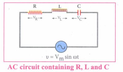
(ii) Let i be the resulting circuit current in the circuit at that instant. As a result, the voltage is developed across R, Land C.
(iii) We know that voltage across R (VR) is in phase with i, voltage across L (VL) leads i by \(\frac { \pi }{ 2 } \) and voltage across C (Vc) lags behind i by \(\frac { \pi }{ 2 } \)
(iv) The phasor diagram is drawn with current as the reference phasor. The current is represented by the phasor \(\vec { OI } \), VR by \(\vec { OA } \); VL by \(\vec { OB } \); Vc by \(\vec { OC } \) as shown in Figure.
(v) The length of these phasors are OI = Im, OA = ImR, OB = ImXL; OC = ImXC
The circuit is either effectively inductive or capacitive or resistive that depends on the value of VL or VC. Let us assume that VL>VC so that nef voltage drop across L-C combination is VL - VC which is represented by a phasor \(\vec { OD } \)
(vi) By parallelogram law, the diagonal \(\vec { OE } \) gives the resultant voltage ሀ of VR and (VL - VC) and its length OE is equal to Vm Therefore,
V2m = V2R + (VL - VC)2 = \(\sqrt { { ({ { I }_{ m }R) } }^{ 2 }+{ ({ I }_{ m }{ X }_{ L }-{ I }_{ m }{ X }_{ C }) }^{ 2 } }=I_m \sqrt {R^2+({X_L-X_C)}^2}\)
or \({ I }_{ m }=\frac { { V }_{ m } }{ \sqrt { R^{ 2 }+({ { X }_{ L }-{ X }_{ C }) }^{ 2 } } } \) ......(2)
\((or) { I }_{ m }=\frac { { V }_{ m } }{ Z } \) where z = \(\sqrt { { R }^{ 2 }+({ { X }_{ L }-{ X }_{ C }) }^{ 2 } } \) ......(3)
(vii) Z is called impedance of the circuit which refers to the effective opposition to the circuit current by the series RLC circuit. The voltage triangle and impedance triangle are given in the Figure.
.JPG)
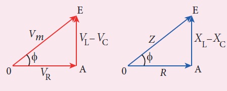
(viii) From phasor diagram, the phase angle between v and i is found out from the following relation
\(tan\phi =\frac { V_{ L }-{ V }_{ C } }{ { V }_{ R } } =\frac { X_{ L }-{ V }_{ C } }{ R } \)
Special cases:
(i) If XL > XC (XL - XC) is positive and phase angle \(\phi \) is also positive. It means that the applied voltage leads the current by \(\phi \) (or current lags behind voltage by \(\phi\)). The circuit is inductive.
∴v = Vm sin ωt; i = Im sin(ωt - \(\phi \))
(ii) If XL < XC (XL - XC) is negative and\(\phi \) is also negative. Therefore current leads voltage by \(\phi \) (or voltage lags behind current by\(\phi \)) and the circuit is capacitive.
∴ = Vm sin ωt; i = Im sin(ωt + \(\phi \))
(ii) If XL = XC \(\phi \) is zero. Therefore current and voltage are in the same phase and the circuit is resistive
∴v = Vm sin ωt, i = Im sinωt
19.
(i) Consider a circuit containing a pure inductor of inductance L connected across an alternating voltage source (Figure). The alternating voltage is given by the equation.
v = Vm sin ωt .......(1)
(ii) The alternating current flowing through the inductor induces a self-induced emf or back emf in the circuit. The back emf is given by
Back emf, ε = \(-L\frac{di}{dt}\)
By applying Kirchoff's loop rule to the purely inductive circuit, we get
v + ε =0
Vm sin ωt = L \(\frac{di}{dt}\)
di = \(\frac{V_m}{L}\) sin ωt dt
Integrating both sides, we get
i = \(\frac{V_m}{L}\) ഽ sin ωt dt
i = \(\frac{V_m}{L_ω}\) (-cos ωt) + constant
.JPG)
(iii) The integration constant in the above equation is independent of time. Since the voltage in the circuit has only time dependent part, we can set the time independent part in the current (integration constant) into zero.
\(i=\frac { { V }_{ m } }{ \omega L } { sin }\left( \omega t-\frac { \pi }{ 2 } \right) \) \(\left[ -{ cos\omega t=-sin\left( \frac { \pi }{ 2 } -\omega t \right) }\\ \because =sin\left( \omega t-\frac { \pi }{ 2 } \right) \right] \)
(or) \(i={ I }_{ m }sin\left( \omega t-\frac { \pi }{ 2 } \right) \) .....(2)
(iv) Where \(\frac { { V }_{ m } }{ \omega L } \) = Im the peak value of the alternating current in the circuit. From equation (1) and (2), it is evident that - current lags behind the applied voltage \(\frac { \pi }{ 2 } \) in an inductive circuit. This fact is depicted in the phasor diagram. In the wave diagram also, it is seen that current lags the voltage by 90° .
(v) Inductive reactance XL:
The peak value of current Im is given by Im = \(\frac { { V }_{ m } }{ \omega L } \). Let us compare this equation with Im = \(\frac { { V }_{ m } }{ R} \) from resistive circuit The quantity ωL plays the same role as the resistance in resistive circuit. This is the resistance offered by the inductor, called inductive reactance (XL) It is measured in ohm.
XL = ωL
.JPG)
20.
21.
(i) We have stated Ampere's law as \(\oint \vec{B} \cdot \overrightarrow{d l}=\mu_oi\)
(ii) Where, i is the electric current crossing a surface bounded by a closed curve and the line integral of \(\vec{B}\) is calculated along that closed curve. This equation is valid only when the electric field at the surface does not change with time.
(iii) Maxwell strongly believed that when the time varying magnetic field produces an electric field, the time varying electric field must produce a magnetic field.
(iv) To understand how a varying electric field produces magnetic field, let us consider a situation of charging a parallel plate capacitor.
.JPG)
(v) Let ic be the conduction current. To calculate the magnetic field at P (fig. 1 ) an amperian loop. S1 is drawn. Applying Ampere circuital law for the surface S1, we get
\(\oint \vec{B} \cdot \overrightarrow{d l}=\mu_0 i_c\) Where, \(\mu_0\) is permeability of free space.
(vi) Applying the same for the surface S2, we get \(\oint \vec{B} \cdot \overrightarrow{d l}=0.\)
Because the surface S2 nowhere touches the wire carrying conduction current. Therefore for the point P at one surface (S1) it has some value and at another surface (S2) it has zero value.
(vii) So, Maxwell believed that there must be a current associated with the changing electric field in between the capacitor and he called that current as displacement current.
(viii) Applying Gauss law to the electric flux between the plates of the capacitor \(\phi_E=\oint \vec{E} \cdot \overrightarrow{\mathrm{dA}}=E A=\frac{q}{\varepsilon_0}\) where, A is the area of the plate.
The change in electric flux is \(\frac{d \phi_F}{d t}=\frac{1}{\varepsilon_0} \frac{d q}{d t} (or) \frac{\mathrm{dq}}{\mathrm{dt}}=\mathrm{i}_{\mathrm{d}}=\varepsilon_0 \frac{\mathrm{d} \phi_{\mathrm{E}}}{\mathrm{dt}}\), where id is the displacement current.
(ix) The displacement current can be defined as the current which comes into play in the region in which the electric field and electric flux are changing with time.
(x) So, Maxwell modified Ampere's law \(\oint_{l} \vec{B} \cdot d \vec{l}=\mu_{0} i_c+\mu_{0}-i_d\) which means the total current enclosed by the surface is sum of conduction current and displacement current.
22.
MaxWell's equations in integral form
i) Gauss law in electricity, \(\oint _s\vec{E} \vec{d} A=\frac{Q_{\text {enclosed }}}{\varepsilon_{o}}\)
ii) Gauss law in magnetism \(\oint _s \vec{B} \cdot \vec{d} A=0\)
iii) Faraday's law \(\oint_l \vec E. \vec {d l}=-\frac{d \phi _B}{d t}\)
iv) Ampere-Maxwell's law \(\oint_l \vec {B}. \vec {d l}=\mu_{o} i_c+\mu_{o} \varepsilon_{o} \frac{d}{d t} \oint_s \vec{E} \cdot {d} \vec A\)

12th Standard Syllabus & Materials
12th Standard
TN 12th Computer Applications களப்பெயர் முறைமை (DNS) Sample Question Papers Study Material - QB365 Set A
NEW12th Standard
TN 12th Computer Applications வலையமைப்பு எடுத்துக்காட்டுகள் மற்றும் நெறிமுறைகள் Sample Question Papers Study Material - QB365 Set A
NEW12th Standard
TN 12th Computer Applications கணினி வலையமைப்பு ஓர் அறிமுகம் Sample Question Papers Study Material - QB365 Set A
NEW12th Standard
TN 12th Computer Applications PHP-உடன் MySQL-ஐ இணைத்தல் Sample Question Papers Study Material - QB365 Set A



Tamilnadu Stateboard 12th Standard Subjects

Maths

Chemistry
Physics

Biology

Computer Science

Business Maths and Statistics

Economics

Commerce

Accountancy

History

Computer Applications
Biology
Computer Technology
Computer Applications
Computer Science
Business Maths and Statistics
Commerce
Economics
Maths
Chemistry
Physics
Computer Technology
History
Accountancy

Tamil

English

French
Tamilnadu Stateboard Standards


