
 100% FREE ACCESS
12th Standard Syllabus & Materials
12th Standard
TN 12th Maths Applications of Matrices and Determinants Sample Question Papers Study Material - QB365 Set A
NEW12th Standard
TN 12th Computer Applications மின்னணு தரவு பரிமாற்றம் Sample Question Papers Study Material - QB365 Set A
NEW12th Standard
TN 12th Computer Applications மின் - வணிக பாதுகாப்பு அமைப்புகள் Sample Question Papers Study Material - QB365 Set A
NEW12th Standard
TN 12th Computer Applications மின்னணு செலுத்தல் முறைகள் Sample Question Papers Study Material - QB365 Set A
NEW12th Standard
TN 12th Computer Applications மின் - வணிகம் Sample Question Papers Study Material - QB365 Set A
NEW12th Standard
TN 12th Computer Applications திறந்த மூல கருத்துருக்கள் Sample Question Papers Study Material - QB365 Set A

Published on: 28/11/2025
Download Tamil Nadu 12th Standard Physics question papers, model tests, one-mark questions, important questions, and public exam papers in PDF format. Free study materials and answer keys for TN State Board students.
Questions + Answers key
Take MCQ Physics Test
1.
Distinguigh between Fresnel Diffraction and Fraun hofer.
2.
3.
State and prove Brewster’s law.
4.
Derive the expression for the torque acting on a bar magnet in uniform magnetiuc field
5.
Discuss the conversion of galvanometer into an ammeter.
6.
Simplify
\(\mathrm{Y}=\mathrm{A} \cdot \overline{\mathrm{B}}+\mathrm{AB}+\mathrm{BC}+\mathrm{CA}\)
7.
Light of wavelength of 5000 Å produces diffraction pattern of the single slit of width 2.5 μm. What is the maximum order of diffraction possible?
8.
What are the advantages and Limitations of FM?
9.
Write the uses of Infrared radiation
10.
A coil of a tangent galvanometer of diameter 0.24 m has 100 turns. If the horizontal component of Earth’s magnetic field is 25 x 10–6 T then, calculate the current which gives a deflection of 60o .
11.
Which colour of light has the highest speed?
Violet
Red
Green
All have same speed
12.
For a transistor, in a common base configuration the alternating current gain is given by ______________.
\({ \left[ \frac { \triangle { I }_{ C } }{ \triangle { I }_{ B } } \right] }_{ { V }_{ c }=constant }\)
\({ \left[ \frac { \triangle { I }_{ B } }{ \triangle { I }_{ C } } \right] }_{ { V }_{ c }=constant }\)
\({ \left[ \frac { \triangle { I }_{ C } }{ \triangle { I }_{ E } } \right] }_{ { V }_{ c }=constant }\)
\({ \left[ \frac { \triangle { I }_{ E } }{ \triangle { I }_{ C } } \right] }_{ { V }_{ c }=constant }\)
13.
14.
Which one of the following is the natural nanomaterial.
Peacock feather
Peacock beak
Grain of sand
Skin of the Whale
15.
The output of the following circuit is 1 when the input ABC is______.
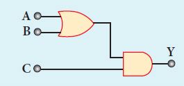
101
100
110
010
16.
17.
The zener diode is primarily used as ______.
Rectifier
Amplifier
Oscillator
Voltage regulator
18.
19.
20.
In a Young’s double-slit experiment, the slit separation is doubled. To maintain the same fringe spacing on the screen, the screen-to-slit distance D must be changed to, _____.
2D
\(\frac{D}{2}\)
\(\sqrt{2}\)D
\(\frac{D}{\sqrt2}\)
21.
Fuse wire is an alloy of _________________.
lead and tin
tin and copper
lead and copper
lead and iron
22.
The vertical component of Earth’s magnetic field at a place is equal to the horizontal component. What is the value of angle of dip at this place?
30°
45°
60°
90°
23.
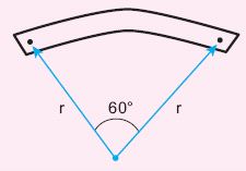
A bar magnet of length l and magnetic moment pm is bent in the form of an arc as shown in Figure. The new magnetic dipole moment will be
pm
\(\frac{3}{\pi} p_{m}\)
\(\frac{2}{\pi} p_{m}\)
\(\frac{1}{2} p_{m}\)
24.
Which of the following is false for electromagnetic waves
transverse
non-mechanical waves
longitudinal
produced by accelerating charges
25.
26.
State the Barkhausen conditions for sustained oscillations
27.
Why are NOR and NAND gates called universal gates?
28.
The ratio of maximum and minimum intensities in an interference pattern is 36 : 1. What is the ratio of the amplitudes of the two interfering waves?
29.
State Fleming's left hand rule.
30.
What is forbidden energy gap?
31.
Mention any two advantages and disadvantages of Robotics.
32.
What are polariser and analyser?
33.
What is magnetic susceptibility?
34.
What is meant by Fraunhofer lines?
35.
What are electromagnetic waves?
36.
Obtain the equation for bandwidth in Young’s double slit experiment.
37.
State and prove De Morgan’s first and second theorem.
38.
Sketch the static characteristics of a common emitter transistor and bring out the essential features of input and output characteristics.
39.
Explain the construction and working of a full wave rectifier
40.
Discuss the experiment to determine the wavelength of monochromatic light using diffraction grating.
41.
Prove law of reflection using Huygens’ principle.
42.
Discuss the working of cyclotron in detail.
43.
Calculate the magnetic field at a point on the axial line of a bar magnet.
44.
Deduce the relation for the magnetic field at a point due to an infinitely long straight conductor carrying current using Biot-Savart law.
45.
Explain the types of emission spectrum.
1.
2.
3.
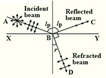
Brewster found experimentally that the reflected and refracted rays are at right angles to each other, when light is incident at polarising angle.
\(\therefore\) ip + 90\(\circ\) + r = 180\(\circ\)
r = 90\(\circ\) - ip
From Snell's law, \(\frac{sin \space i}{sin \space r}=\mu\)
\(\therefore \frac{sin \space i_{p}}{sin(90-i_{p})}=\mu \)
\(\frac{sin \space i_{p}}{cos \space i_{p}}=\mu \)
(or) \(\mu\) = tan ip
Tangent of the polarising angle is numerically equal to the refractive index of the medium.
4.
(i) Bar magnet (magnetic dipole) of dipole moment \(\overrightarrow{p_m}\) is heldat an angle \(\theta\) with the directions of a uniform magnetic field \(\vec{B}\).
(ii) The magnitude of the torque acting on the dipole is \(\left|\overrightarrow{\tau_B}\right|=\left|\overrightarrow{p_m}\right||\vec{B}| \sin \theta\)
(iii) If the dipole is rotated through a very small angular displacement d\(\theta\) against the torque \(\tau_B\) at constant angular velocity, then the work done by external torque \(\left(\vec{\tau}_{e x t}\right)\).
\(\mathrm{dW}=\left|\vec{\tau}_{e x t}\right| d \theta\)
(iv) Since the bar magnet to be moved at constant angular velocity, it implies \(\left|\vec{\tau}_B\right|=\left|\vec{\tau}_{e x t}\right|\)
\(\mathrm{dW}=P_{\mathrm{m}} B \sin \theta d \theta\)
Total work done in rotating the dipole from \(\theta\)' to \(\theta\) is
\(\mathrm{W}=\int_{\theta^{\prime}}^\theta \tau d \theta\)
\(=\int_{\theta^{\prime}}^\theta P_m B \sin \theta d \theta=P_m B(-\cos \theta d \theta)_{\theta^{\prime}}^\theta\)
\(\mathrm{W}=-p_m B\left(\cos \theta-\cos \theta^{\prime}\right)\)
This work done is stored as potential energy
\(
\mathrm{U}=-p_m B\left(\cos \theta-\cos \theta^{\prime}\right)
\) ........(i)
\(
If \theta^{\prime}=90^{\circ}, \cos 90=1
\)
\(
\mathrm{U}=-p_{\mathrm{n}} B(\cos \theta)
\) ..............(ii)
The potential energy stored in a bar magnet in a uniform magnetic field is given by,
\(\mathrm{U}=-\vec{p}_m \cdot \vec{B}\) .............(iii)
5.
Biot-Savart's law states that the magnitude of magnetic field \(d\vec { B } \) at a point P at a distance r from the small elemental length taken on a conductor carrying current varies
(i) directly as the strength of the current I
(ii) directly as the magnitude of the length of element \(\vec { dl } \)
(iii) directly as the sine of the angle (say,θ) between \(\vec { dl } \) and \(\hat { r } \).
(iv) inversely as the square of the distance between the point P and length element \(\vec { dl } \).
\(d\vec { B } =\frac { { \mu }_{ 0 } }{ 4\pi } \frac { I\vec { dl } \times \hat { r } }{ { r }^{ 2 } } \)
6.
\(Y =A \cdot \bar{B}+A B+B C+C A
\)
\(=A(\bar{B}+B)+B C+C A[\bar{B}+B=1]
\)
\(=A(1)+B C+C A
\)
\(=A+C A+B C
\)
\(=A(1+C)+B C[1+C=1]
\)
= A + BC
7.
λ = 5000 Å = 0.5 x 10⁻⁶ m,
a = 2.5 μm = 2.5 x 10⁻⁶ m
We know, a sin θ = nλ
For maximum order of diffraction, sin θ = 1
Therefore, 2.5 x 10-6 = n x 0.5 x 10⁻⁶
\(n=\frac{2.5}{0.5}=5\)
Maximum order of diffraction = 5.
8.
Advantages of AM :
(i) Easy transmission and reception
(ii) Lesser bandwidth requirements
(iii) Low cost
Limitations of AM :
i) Noise level is high
i) Low efficiency
ii) Small operating range
9.
It provides electrical energy to satellites by means of solar cells. It is used to produce dehydrated fruits, in green houses to keep the plants warm, heat therapy for muscular pain or sprain, TV remote as a signal carrier, to look through haze fog or mist and used in night vision or infrared photography.
10.
The diameter of the coil is 0.24 m. Therefore, radius of the coil is 0.12 m.
Number of turns is 100 turns. Earth’s magnetic field is 25 x 10-6 T
Deflection is
\(\theta =60°\Rightarrow tan60°=\sqrt { 3 } =1.732\)
\(I=\frac { 2R{ B }_{ H } }{ { \mu }_{ ° }N } tan\theta \)
\(=\frac { 2\times 0.12\times 25\times 1{ 0 }^{ -6 } }{ 4\times 1{ 0 }^{ -7 }\times 3.14\times 100 } \times 1.732=0.82\times 1{ 0 }^{ -1 }A\)
I = 0.082 A
11.
(d)
All have same speed
12.
(c)
\({ \left[ \frac { \triangle { I }_{ C } }{ \triangle { I }_{ E } } \right] }_{ { V }_{ c }=constant }\)
13.
(c)
14.
Wings of a morpho butterfly, peacock feathers, lotus leaf surface and sources of parrot fish's bite are some of the natural nano particles.
15.
A = 1, B = 0, C = 1
y = A + B, y = (A + B).C
y = (1 + 0).1 ⇒ y = 1
16.
(d)
17.
(d)
Voltage regulator
18.
(d)
19.
(b)
20.
d' = 2d, β' = β, D' = ?
W.K.T, Fringe width
\(\beta = \frac{D\lambda}{d} \Rightarrow D' = \frac{Dd'}{d}\)
\(D' = \frac{D2d}{d}=2D\)
21.
(a)
lead and tin
22.
\(tan \ I=\frac{B_V}{B_H}=1\)
∴ I = 45o
23.
Magnetic moment,
p'm = ml
From figure, \(l=\frac{\pi r}{3}\)
\(\therefore r=\frac{3l}{\pi}\)
∴ New magnetic moment,
p'm = m x r
\(=m\times \frac{3l}{\pi}=\frac{3}{\pi}ml\)
∴ p'm = \(\frac{3}{\pi}p_m\)
24.
(c)
longitudinal
25.
(b)
26.
(i) The loop phase shift must be 0o or integral multiples of 2\(\pi\) .
(ii) The loop gain must be unity \(|A \beta|=1\)
\(\alpha\) \(\rightarrow\) voltage gain of the amplifier
\(\beta \rightarrow\) feed back ratio
27.
NAND and NOR gates are known as universal gates because any other logic gate can be made from NAND or NOR gates.
28.
\(\frac{\mathrm{I}_{\max }}{\mathrm{I}_{\min }}=\frac{36}{1}\)
If a1 and a2 are their amplitudes,
\(\frac{\mathrm{I}_{\max }}{\mathrm{I}_{\min }}=\frac{\left(\mathrm{a}_{1}+\mathrm{a}_{2}\right)^{2}}{\left(\mathrm{a}_{1}-\mathrm{a}_{2}\right)^{2}}=\frac{36}{1}\) (or) \(\frac{a_{1}+a_{2}}{a_{1}-a_{2}}=\frac{6}{1}\)
6a1 - 6a2 = a1 + a2
5a1 - 7a2 = 5a1 = 7a2
\(\frac{a_{1}}{a_{2}}=\frac{7}{5}\)
a1 : a2 = 7 : 5
29.
(i) Stretch out forefinger, the middle finger and the thumb of the left hand such that they are in three mutually perpendicular directions.
(ii) If the forefinger points in the direction of magnetic field, the middle finger in the direction of the electric current, then thumb will point in the direction of the force experienced by the conductor.
30.
The energy gap between the valance band and conduction band is called forbidden energy gap
31.
Advantages of Robotics:
(i) Robots are more precise and error free in performing the task.
(ii) Robots never get tired like humans. It can work for 24 x 7. Hence absenteeism in work place can be reduced.
Disadvantages of Robotics:
(i) Unemployment problem will increase.
(ii) Robots can perform defined tasks and cannot handle unexpected situations.
32.
(i) The polaroid which polarises the light passing through it is called a polariser.
(ii) The polaroid which is used to examine whether a beam of light is polarised or not is called an analyser.
33.
Magnetic susceptibility is defined as the ratio of the intensity of magnetisation (\(\vec { M } \)) induced in the material due to the magnetising field |\(\vec H\)|.
\( \chi _{ m }=\frac { |\vec { M } | }{ |\vec { H } | } \).
34.
When the spectrum obtained from the Sun is examined, it consists of large number of dark lines (line absorption spectrum). These dark lines in the solar spectrum are known as Fraunhofer lines.
35.
An electromagnetic waves are the waves that are radiated by an accelerated charge which propagates through space as coupled electric and magnetic fields, oscillating perpendicular to each other and to the direction of propagation of the wave.
36.
Condition for bright fringe (or) maxima :
The condition for the point P to have a constructive interference (or) be a bright fringe Is,
Path diference, δ = nλ Where, n = 0, 1, 2,....
\(\therefore\frac{dy}{D}=n\lambda\)
\(y=n\frac{\lambda D}{d}(or)y_n=n\frac{\lambda D}{d}\) .....(4)
This is the condition for the point P to have a bright fringe. The distance yn is the distance or the nth bright fringe from the point O.
Condition for dark fringe (or) minima:
The condition for the point P to have a destructive interference (or) be a dark fringe is,
Path difference, δ = \((2n-1)\frac{\lambda}{2}\) Where, n = 1, 2, 3....
\(\therefore\frac{dy}{D}=(2n-1)\frac{\lambda}{2}\)
\(y=\left(\frac{(2n-1)}{2} \frac{\lambda D}{d}\right)(or)\left(\frac{(2 n-1)}{2} \frac{\lambda D}{d}\right) \) .....(5)
This is the condition for the point P to have a dark fringe. The distance yn is the distance of the nth dark fringe from the point O
Bandwidth:
The bandwidth \((\beta)\) is defined as the distance between any two consecutive bright or dark fringes.
\(\beta=y_{(n+1)}-y_{n}=\left((n+1) \frac{\lambda D}{d}\right)-\left(n \frac{\lambda D}{d}\right) \)
\(\beta=\frac{\lambda D}{d} \) .....(6)
Bright and Dark tinges are of same width equally spaced on either side of the central bright fringe.
37.
First Theorem :
The complement of the sum of two logical inputs is equal to the product of its complements.
\(\overline { A+B } \) = \(\bar { A } .\bar { B } \)
Proof:
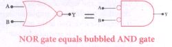
(i) The Boolean equation for NOR gate is Y = \(\overline { A+B } \)
(ii) The Boolean equation for a bubbled AND gate is Y =\(\bar { A } .\bar { B } \)
(iii) Both cases generate same outputs for same inputs. It can be verified using the following truth
| A | B | A+B | \(\overline { A+B } \) | Ā | \(\bar { B } \) | \(\bar { A } .\bar { B } \) |
| 0 | 0 | 0 | 1 | 1 | 1 | 1 |
| 0 | 1 | 1 | 0 | 1 | 0 | 0 |
| 1 | 0 | 1 | 0 | 1 | 0 | 0 |
| 1 | 1 | 1 | 0 | 0 | 0 | 0 |
(i) From the above truth table, we can conclude \(\overline { A+B } \) = \(\bar { A } .\bar { B } \)
(ii) Thus De Morgan's first theorem is proved.
(iii) Hence, a NOR gate is equal to a bubbled AND gate
Second theorem :
The complement of the product of two is equal to the sum of its complements
\(\overline { A.B } \) = \(\bar { A } +\bar { B } \)
Proof:
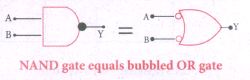
(i) The Boolean equation for NAND gate is Y = \(\overline { A.B } \)
(ii) The Boolean equation for bubbled OR gate is Y = \(\bar { A } +\bar { B } \)
(iii) A and B are the inputs and Y is the output. The above two equations produces the same output for the same inputs. It can be verified by using the truth table.
| A | B | A+B | \(\overline{\mathrm{A}. \mathrm{B}}\) | Ā | \(\bar { B } \) | \(\overline{\mathrm{A}}+\overline{\mathrm{B}}\) |
| 0 | 0 | 0 | 1 | 1 | 1 | 1 |
| 0 | 1 | 0 | 1 | 1 | 0 | 1 |
| 1 | 0 | 0 | 1 | 0 | 1 | 1 |
| 1 | 1 | 1 | 0 | 0 | 0 | 0 |
(i) From the above truth table, we can conclude \(\overline { A.B } \) = \(\bar { A } +\bar { B } \)
(ii) Thus, De Morgan's second therom is proved.
(iii) Hence, a NAND gate is equal to a bubbled OR gate.
38.
.JPG)
The static characteristics of the BJT are
(i) Input characteristics
(ii) Output characteristics
(iii) Transfer characteristics.
(i) Input characteristics:
Input characteristics curves give the relationship between the base current (IB) and base to emitter voltage (vBE) at constant collector to emitter voltage (vCE) and are shown in figure
.JPG)
(i) Initially, the collector to emitter voltage (VCE) is set to a particular value (above 0.7 V to reverse bias the junction).
(ii) Then the base-emitter voltage VBE, is increased in suitable steps and the corresponding base-current IB is recorded.
(iii) A graph is plotted with VBE along the x axis and IB along the Y - axis
(iv) The procedure is repeated for different values of VcE
The following observations are made from the graph :
(i) The Curve looks like the forward characteristics of an ordinary p - n junction diode.
(ii) There exists a threshold voltage (or) knee voltage (Vknee) below which the base current (Ib) is very small. This value is 0.7 V for silicon and 0.3 V for germanium transistors. Beyond the knee voltage, the base current increases with the increase in base-emitter voltage.
(iii) It is also noted the increase in VCE, decreases the IB. This shifts the curve outward.
(iv) This is because the increase in collector-emitter voltage increases the width of the depletion region which in turn, reduces the effective base width and thereby the base current.
Input resistance :
The ratio of the change in base-emitter voltage (∆VBE) to the change in base current (∆LB) at a constant collector-emitter voltage (VCE) is called the input resistance (ri)
\(\mathrm{R}_{\mathrm{i}}=\left[\frac{\Delta \mathrm{V}_{\mathrm{BE}}}{\Delta \mathrm{I}_{\mathrm{B}}}\right]_{\dot{\mathrm{V} C \mathrm{E}}}\)
The input impedance is high for a transistor in common emitter configuration.
Output characteristics :
The output characteristics give the relationship between the collector current (Ic) and the collector -emitter voltage (VCE) at constant input current (IB)
as shown in figure
.JPG)
(i) Initially IB is set to a particular voltage. VCE is increased in suitable steps and IC is recorded
(ii) A graph is plotted with the VCE along the x-axis and IC along the y - axis
(iii) This procedure is repeated for different values IB
The four important regions ln the output characteristics
(i) Saturation region
(ii) Cut-off region
(iii) Active region
(iv) Breakdown region
Output Resistance :
The ratio of the change in the collector emitter voltage (∆VCE) to the corresponding change in the collector current (∆lC) at constant base current (IB) is called output resistance (ro).
\(\mathrm{R}_{\mathrm{o}}=\left[\frac{\Delta \mathrm{V}_{\mathrm{BE}}}{\Delta \mathrm{I}_{\mathrm{C}}}\right]_{\mathrm{l}_{\mathrm{B}}}\)
The output impedance for transistor in common emitter configuration is very low.
39.
FuIl wave rectifier :
The positive and negative half cycles of the AC input signal pass through the full wave rectifier circuit and hence it is called the full wave rectifier
Construction:
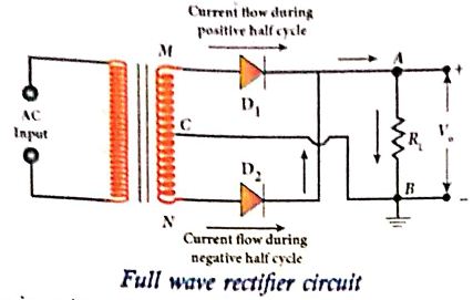
(i) It consists of two p-n junction diodes, a center-tapped transformer, and a load resistor (R1)
(ii) The centre is usually taken as the ground or zero voltage reference point.
(iii) Due to the centre tap transformer, the output voltage rectified by each diode is only one-half of the total secondary voltage.
Working:
During positive half cycle :
(i) When the positive half cycle of the ac input signal passes through the circuit, terminal M is positive, G is at zero potential and N is at negative potential.
(ii) This forward biases diode D1 and reverse biases diode D2.
(iii) Hence, being forward biased, diode D1 conducts and current flows along the path MD1AGC.
During negative half cycle:
(i) When the negative half cycle of the AC input signal passes through the circuit, terminal N becomes positive, C is at zero potential and M is at negative potential.
(ii) This forward biases diode D2 and reverse biases diode D1.
(iii) Hence, being forward biased, diode D2 conducts and current flows along the path ND2BGC.
(iii) During both positive and negative half cycles of the input signal, the current flows through the load in same direction.
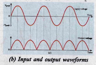
(iv) The output signal corresponding to the input signal is shown in Figure. Though both half cycles of AC input are rectified, the output is still pulsating in nature.
(v) The efficiency (η) of full wave rectifier is twice that of a half wave rectifier and is found to be 81.2 %.
40.
(i) The wavelength of a spectral line can be very accurately determined with the help of a diffraction grating. For that we need to use an instrument called spectrometer.
(ii) The slit of collimator is illuminated by a monochromatic light, whose wavelength is to be determined.
(iii) The telescope is brought in line with collimator to view the image of the slit.
(iv) The given plane transmission grating is then mounted on the prism table with its plane perpendicular to the incident beam of light coming from the collimator.
(v)The telescope is turned to one side until the first order diffraction image of the slit coincides with the vertical cross wire of the eye piece.
(vi) The reading of the position of the telescope is noted.
(vii) Similarly the first order diffraction image on the other side is made to coincide with the vertical cross wire and corresponding reading is noted.
(viii) The difference between two positions gives 2θ. Half of its value gives θ, the diffraction angle for first order maximum as shown in Figure.
The wavelength of light is calculated from the equation.
\(\\ \lambda =\cfrac { sin\theta }{ Nm } \)
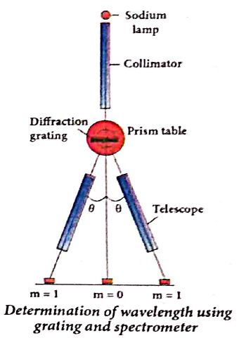
(ix) Here, N is the number of rulings per metre in the grating and m is the order of the diffraction image.
41.
(i) Let us consider a parallel beam of light, incident on a reflecting plane surface such as a plane mirror XY.
(ii) The incident wavefront is AB and the reflected waterfront is A'B'.
(iii) These wavefronts are perpendicular to the incident rays L, M and reflected rays L', M', respectively.
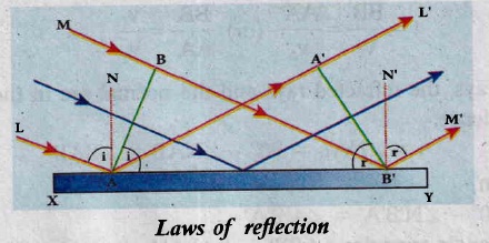
(i) The incident rays, the reflected rays and the normal are in the same plane.
(ii) Angle of incidence, ∠i = ∠NAL = 90°- ∠NAB = ∠BAB'
Angle of reflection ∠r = ∠N'B'M = 90°- ∠N'B'A'= ∠A'B'A
(a) For the two right angle triangles, ∆ABB' and ∆B'A'A, the two right angles, ∠B and ∠A' are equal, (∠B and ∠A' = 90°); the two sides., AA' and BB' are equal, (AA' = BB'); the side AB' is common
(b) Thus the two triangles are congruent. As per the property of congruency, the two angles, ∠BAB' and ∠A'B'A must also be equal.
i = r
Hence, the laws of reflection are proved.
42.
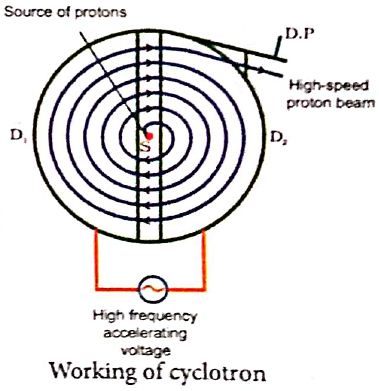
Cyclotron:
Device used to accelerate the charged particles to gain large kinetic energy.
Principle:
When a charged particle moves perpendicular to the magnetic field, it experiences magnetic Lorentz force.
Construction:
(i) The particles are allowed to move in between two semi-circular metal containers called Dees (hollow D - shaped objects).
(ii) The uniform magnetic field is controlled by an electromagnet. The direction of magnetic field is normal to the plane of the Dees.
(iii) Source is kept between two Dees.
(vi) Dees are connected to high frequency alternating potential difference.
Working:
(i) The ion ejected from source is positively charged.
(ii) It is accelerated towards negative potential Dees
(iii) This ion undergoes a circular path.
(iv) At this time, the polarities of the Dees are reversed, so that the ion is now accelerated towards Dee-2 with a greater velocity. For this circular motion, the centripetal force of the charged particle q is provided by Lorentz force.
\(\frac { m{ v }^{ 2 } }{ r } \) = qvB
⇒ r = \(\frac { m }{ qB } \)v ........(1)
⇒ r ∝ v
(v) If radius of the circular paths, increases, velocity also increases particles undergo spiral path with increasing radius.
(vi) When the frequency f at which the positive ion ciculates in the magnetic field must be equal to the constant frequency of the electrical oscillator fosc. This is called Resonance condition.
From equation, f = \(\frac { qB }{ 2\pi m } \) we have
fosc = \(\frac { qB }{ 2\pi m } \),
The time period of oscillation is
T = \(\frac { 2\pi m }{ qB } \)
The kinetic energy of the charged particle is,
KE = \(\frac { 1 }{ 2 } mv^{ 2 }=\frac { { q }^{ 2 }B^{ 2 }{ r }^{ 2 } }{ 2m } \) ........(2)
Limitations:
(i) The speed of ion is limited.
(ii) Electron cannot be accelerated.
(iii) Uncharged particles cannot be accelerated.
43.
(i) Consider a bar magnet NS whose pole strength is qm and length is 2l.
(ii) Let C be the point along axis of maget.
(iii) The magnetic field at a point C (lies along the axis of the magnet) at a distance r from the geometrical center O of the bar magnet can be computed by keeping unit north pole (qmc = 1 A m) at C.
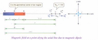
The magnetie field at C due to the north pole is,
\(\vec { { B }_{ N } } =\frac { { \mu }_{ 0 } }{ 4\pi } \frac { { q }_{ m } }{ (r-l)^{ 2 } } \hat { i } \)
where (r - I) is the distance between north pole of the bar magnet and unit north pole at C. The magnetic field at C due to the south pole is,
\(\vec { { B }_{ S } } =-\frac { { \mu }_{ 0 } }{ 4\pi } \frac { { q }_{ m } }{ (r+l)^{ 2 } } \hat { i } \)
where (r + I) is the distance between south pole of the bar magnet and unit north pole at C. The net magnetic field due to magnetic dipole at a point C
\(\vec { B } =\vec { { B }_{ N } } +\vec { B_{ S } } \)
\(\vec { B } =\frac { { \mu }_{ 0 } }{ 4\pi } \frac { { q }_{ m } }{ (r-l)^{ 2 } } \hat { i } +\left(- \frac { { \mu }_{ 0 } }{ 4\pi } \frac { { q }_{ m } }{ (r+l)^{ 2 } } \hat { i } \right) \)
\(\vec { B } =\frac { { \mu }_{ 0 }{ q }_{ m } }{ 4\pi } \left( \frac { 1 }{ (r-l)^{ 2 } } -\frac { 1 }{ (r+l)^{ 2 } } \right) \hat { i } \)
\(\vec { B } =\frac { { \mu }_{ 0 }2r }{ 4\pi } \left( \frac { { q }_{ m }.(2l) }{ ({ r }^{ 2 }-{ l }^{ 2 })^{ 2 } } \right) \hat { i } \)
Since, magnitude of magnetic dipole moment is \(|\vec { { p }_{ m } } |\) = pm = qm. 2l the magnetic field at a point C can be written as,
\(\vec { { B }_{ axial } } =\frac { { \mu }_{ 0 } }{ 4\pi } \left( \frac { 2rp_{ m } }{ { (r^2-l^2)}^{ 2 } } \right) \hat { i } \)
If r >> I then, (r2 - l2)2 ≈ r4
\( { { \vec B }_{ axial } } =\frac { { \mu }_{ 0 } 2r}{ 4\pi } \left( \frac { p_{ m } }{ { r }^{ 4 } } \right) \hat { i } =\frac { { \mu }_{ 0 } }{ 4\pi }[ \frac { 2 \vec p_{ m } }{ { r }^{ 3 }}] \)
∵ \(\vec { { p }_{ m } } =p_{ m }\hat { i } \).
44.
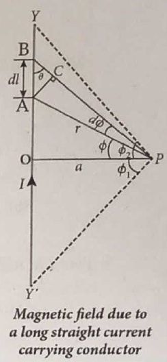
Let YY' be an infinitely long straight conductor carry current I. In order to calculate magnetic field at a point P which is at a distance a from the wire, let us consider a small line element dl (segment AB).
According to Biot Savart law, the magnetic field at a point P due to current element Idl is,
\({ d \vec B } =\frac { { \mu }_{ 0 } }{ 4\pi } \frac { { Idl sin \theta} }{ { r }^{ 2 } }\hat n \).
To apply trigonometry, draw a perpendicular AC to the line BP as shown in Figure.
In triangle ΔABC, \(\sin \theta=\frac{\mathrm{AC}}{\mathrm{AB}}\)
∴ AC = AB sinθ
\(\text { But, } A B =d l \Rightarrow A C=d l \sin \theta\)
Let dΦ be the angle subtended between AP and BP
ie., \(\angle \mathrm{APB}=\angle \mathrm{APC}=d \phi\)
In a triangle \(\triangle \mathrm{APC}, \sin (d \phi) \simeq A C / A P\)
Since, dΦ is very small, \(\sin (d \phi) \simeq d \phi\)
But, \(\mathrm{AP} =r \Rightarrow A C=r d \phi \)
\(\therefore \mathrm{AC} =d l \sin \theta=r d \phi \)
\(\therefore d \vec{B} =\frac{\mu_0}{4 \pi} \frac{I}{r^2}(r d \phi) \hat{n}=\frac{\mu_0}{4 \pi} \frac{I d \phi}{r} \hat{n}\)
Let Φ be the angle between AP and OP
\(\text {In a } \triangle \mathrm{OPA}, \cos \phi =\frac{\mathrm{OP}}{\mathrm{AP}}=\frac{\mathrm{a}}{\mathrm{r}} \)
\(r =\frac{a}{\cos \phi} \)
\(\text {Now, } d \vec{B} =\frac{\mu_0}{4 \pi} \frac{I}{a / \cos \phi} d \phi . \hat{n} \)
\(d \vec{B} =\frac{\mu_0 I}{4 \pi a} \cos \phi d \phi \hat{n}\)
The total magnetic field at P due to the conductor YY' is
\(\vec { B } = \int _{- \Phi _{ 1 } }^{ { \Phi }_{ 2} }d\vec B =\int _{ -\Phi _{ 1 } }^{ { \Phi }_{ 2 } }\frac { { \mu }_{ 0 }I }{ 4\pi a }{ cos\phi d\phi } \hat { n }\)
\(=\frac { { \mu }_{ 0 }I }{ 4\pi a }[{ sin\phi ]^{\phi_2} _{\phi_-1}} \hat { n }\)
\( \vec{B}=\frac { { \mu }_{ 0 }I }{ 4\pi a } (sin{ \Phi }_{ 1 }+sin{ \Phi }_{ 2 })\hat { n } \)
For infinitely long conductor, Φ1 = Φ2 = 90o
\(\therefore \vec{B}=\frac { { \mu }_{ 0 }I }{ 4\pi a } \times 2\hat{n}\Rightarrow\vec { B } =\frac { { \mu }_{ 0 }I }{ 2\pi a } \hat { n } \)
45.
Emission spectra:
When the spectrum of self luminous source is taken, we get emission spectrum. Each source has its own characteristic emission spectrum. The emission spectrum can be divided into three types:
(i) Continuous emission spectra (or continuous spectra) :
(a) If the light from incandescent lamp (filament bulb) is allowed to pass through prism (simplest spectroscope), it splits into seven colours.
(b) Thus, it consists of wavelengths containing all the visible colours ranging from violet to red (in the figure). Examples: spectrum obtained from carbon arc, incandescent solids.
(ii) Line emission spectrum (or line spectrum) :
(a) Suppose light from hot gas is allowed to pass through a prism, line spectrum is observed. Line spectra are also known as discontinuous spectra. The line spectra consists of sharp lines of definite wavelengths or frequencies.
(b) Such spectra arise due to excited atoms of elements. These lines are the characteristics of the element and are different for different elements. Examples: spectra of atomic hydrogen, helium, etc.
(iii) Band emission spectrum (or band spectrum) :
(a) Band spectrum consists of several number of very closely spaced spectral lines which overlapped together forming specific bands which are separated by dark spaces.
(b) This spectrum has a sharp edge at one end and fades out at the other end. Such spectra arise when the molecules are excited.
(c) Band spectrum is the characteristic of the molecule hence, the structure of the molecules can be studied using their band spectra. Examples, spectra of hydrogen gas, ammonia gas in the discharge tube, etc.

12th Standard Syllabus & Materials
12th Standard
TN 12th Computer Applications வலையமைப்பு வடமிடல் Sample Question Papers Study Material - QB365 Set A
NEW12th Standard
TN 12th Computer Applications களப்பெயர் முறைமை (DNS) Sample Question Papers Study Material - QB365 Set A
NEW12th Standard
TN 12th Computer Applications வலையமைப்பு எடுத்துக்காட்டுகள் மற்றும் நெறிமுறைகள் Sample Question Papers Study Material - QB365 Set A
NEW12th Standard
TN 12th Computer Applications கணினி வலையமைப்பு ஓர் அறிமுகம் Sample Question Papers Study Material - QB365 Set A



Tamilnadu Stateboard 12th Standard Subjects

Maths

Chemistry
Physics

Biology

Computer Science

Business Maths and Statistics

Economics

Commerce

Accountancy

History

Computer Applications
Biology
Computer Technology
Computer Applications
Computer Science
Business Maths and Statistics
Commerce
Economics
Maths
Chemistry
Physics
Computer Technology
History
Accountancy

Tamil

English

French
Tamilnadu Stateboard Standards


