
 100% FREE ACCESS
12th Standard Syllabus & Materials
12th Standard
TN 12th Maths Applications of Matrices and Determinants Sample Question Papers Study Material - QB365 Set A
NEW12th Standard
TN 12th Computer Applications மின்னணு தரவு பரிமாற்றம் Sample Question Papers Study Material - QB365 Set A
NEW12th Standard
TN 12th Computer Applications மின் - வணிக பாதுகாப்பு அமைப்புகள் Sample Question Papers Study Material - QB365 Set A
NEW12th Standard
TN 12th Computer Applications மின்னணு செலுத்தல் முறைகள் Sample Question Papers Study Material - QB365 Set A
NEW12th Standard
TN 12th Computer Applications மின் - வணிகம் Sample Question Papers Study Material - QB365 Set A
NEW12th Standard
TN 12th Computer Applications திறந்த மூல கருத்துருக்கள் Sample Question Papers Study Material - QB365 Set A

Published on: 28/11/2025
Download Tamil Nadu 12th Standard Physics question papers, model tests, one-mark questions, important questions, and public exam papers in PDF format. Free study materials and answer keys for TN State Board students.
Questions + Answers key
Take MCQ Physics Test
1.
2.
What is photo emissive cell?
3.
A radiation of wavelength 300 nm is incident on a silver surface. Will photoelectrons be observed? [work function of silver = 4.7 eV]
4.
What is photoelectric effect?
5.
Distinguish between the electric potential and potential energy and state the relation between them.
6.
What is corona discharge?
7.
What is meant by ‘electric field lines’?
8.
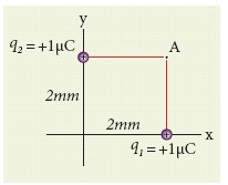
Consider the charge configuration as shown in the figure. Calculate the electric field at point A. If an electron is placed at points A, what is the acceleration experienced by this electron? (mass of the electron = 9.1 x 10⁻³¹ kg and charge of electron = −1.6 x 10⁻¹⁹ C)
9.
If the frequency of light in a photo electron experiment is doubled the stopping potential will ______________.
be doubled
be halved
become more than double
become less than double.
10.
Emission of electrons by the absorption of heat energy is called ______ emission.
photoelectric
field
thermionic
secondary
11.
A light of wavelength 500 nm is incident on a sensitive metal plate of photoelectric work function 1.235 eV. The kinetic energy of the photoelectrons emitted is_____. (Take h = 6.6 x 10⁻³⁴ Js)
0.58 eV
2.48 eV
1.24 eV
1.16 eV
12.
If the mean wavelength of light from sun is taken as 550 nm and its mean power as 3.8 x 1026 W, then the number of photons emitted per second from the sun is of the order of _____.
1045
1042
1054
1051
13.
A photoelectric surface is illuminated successively by monochromatic light of wavelength λ and λ /2. If the maximum kinetic energy of the emitted photoelectrons in the second case is 3 times that in the first case, the work function of the material is _____.
\(\frac{hc}{\lambda}\)
\(\frac{2hc}{\lambda}\)
\(\frac{hc}{3\lambda}\)
\(\frac{hc}{2\lambda}\)
14.
In an electron microscope, the electrons are accelerated by a voltage of 14 kV. If the voltage is changed to 224 kV, then the de Broglie wavelength associated with the electrons would _____.
increase by 2 times
decrease by 2 times
decrease by 4 times
increase by 4 times
15.
The wavelength λe of an electron and λp of a photon of same energy E are related by _____.
λp ∝ λe
\({ \lambda }_{ p }∝ \sqrt { { \lambda }_{ e } } \)
\({ \lambda }_{ p }∝ \frac { 1 }{ \sqrt { { \lambda }_{ e } } } \)
\({ \lambda }_{ p }∝ { \lambda }_{ e }^{ 2 }\)
16.
The electrostatic force obeys _______.
Newton's I law
Newton's II law
Newton's III law
none of the above
17.
Two metallic spheres of radii 1 cm and 3 cm are given charges of -1 \(\times\) 10-2 C and 5 \(\times\) 10-2 C respectively. If these are connected by a conducting wire, the final charge on the bigger sphere is
3 \(\times\) 10-2 C
4 \(\times\) 10-2 C
1 \(\times\) 10-2 C
2 \(\times\) 10-2 C
18.
A parallel plate capacitor stores a charge Q at a voltage V. Suppose the area of the parallel plate capacitor and the distance between the plates are each doubled then which is the quantity that will change?
Capacitance
Charge
Voltage
Energy density
19.
If voltage applied on a capacitor is increased from V to 2V, choose the correct conclusion.
Q remains the same, C is doubled
Q is doubled, C doubled
C remains same, Q doubled
Both Q and C remain same
20.
An electric field \(\vec { E } =10x\hat { i } \) exists in a certain region of space. Then the potential difference V = Vo – VA, where Vo is the potential at the origin and VA is the potential at x = 2 m is _____.
10 V
-20 V
+20 V
-10 V
21.
Two identical conducting balls having positive charges q1 and q2 are separated by a centre to centre distance r. If they are made to touch each other and then separated to the same distance, the force between them will be _____.
less than before
same as before
more than before
zero
22.
23.
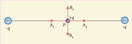
Two identical point charges of magnitude –q are fixed as shown in the figure below. A third charge +q is placed midway between the two charges at the point P. Suppose this charge +q is displaced a small distance from the point P in the directions indicated by the arrows, in which direction(s) will +q be stable with respect to the displacement?
A1 and A2
B1 and B2
both directions
No stable
24.
Describe briefly Davisson – Germer experiment which demonstrated the wave nature of electrons.
25.
Briefly explain the principle and working of electron microscope.
26.
What do you mean by electron emission? Explain briefly various methods of electron emission.
27.
Derive the expression for resultant capacitance, when capacitors are connected in series and in parallel.
28.
Explain in detail the effect of a dielectric placed in a parallel plate capacitor.
29.
Calculate the electric field due to a dipole on its axial line and equatorial plane.
30.
How do photo emissive cell, photo voltaic cell and photo conductive cell differ in their action?
31.
What is the threshold frequency for photoelectric emission? Does it depend upon the intensity of light?
32.
Where is Van de Graff generator used?
33.
State the superposition principle of electric fields.
34.
Give the applications photocell.
35.
List out the laws of photoelectric effect. (or) Write any three Laws of Photoelectric Effect
36.
Find the de Broglie wavelength associated with an alpha particle which is accelerated through a potential difference of 400 V. Given that the mass of the proton is 1.67 x 10⁻²⁷ kg.
37.
Obtain the expression for energy stored in the parallel plate capacitor.
38.
Derive an expression for electrostatic potential due to a point charge.
1.
2.
Its working depends on the electron emission from a metal cathode due to irradiation of light or other radiations.
3.
Energy of the incident photon is
E = hv = \(\frac { hc }{ \lambda } \) (in joules)
E = \(\frac { hc }{ \lambda e } \) (in eV)
Substituting the known values, we get
E = \(\frac { 6.626\times { 10 }^{ -34 }\times 3\times 10^{ 8 } }{ 300\times { 10 }^{ -9 }\times 1.6\times { 10 }^{ -19 } } \)
E = 4.14 eV
The work function of silver = 4.7 eV. Since the energy of the incident photon is less than the work function of silver, photoelectrons are not observed in this case.
4.
The ejection of electrons from the metal plate when illuminated by light or any electromagnetic radiation of suitable wavelength (or frequency) is called photoelectric effect.
5.
While electric potential is work done per unit charge the potential energy is the total work done in bringing different charges from infinity to their respective positions.
\(V=\frac { { 1 } }{ 4\pi { \varepsilon }_{ 0 }^{ } } .\frac { { q }_{ 1 } }{ r } and\quad U=\frac { { 1 } }{ 4\pi { \varepsilon }_{ 0 }^{ } } .\frac { { q }_{ 1 }{ q }_{ 2 } }{ r } \)
\(U={ q }_{ 2 }\left[ \frac { { 1 } }{ 4\pi { \varepsilon }_{ 0 }^{ } } .\frac { { q }_{ 1 } }{ r } \right] ={ q }_{ 2 }V\)
∴ Electric potential energy = charge q2 x potential due to charge q1 at the location of charge q2.
6.
When an irregular shaped conductor is given positive charge, the electric field near the sharp end is very high and it ionizes the surrounding air. The positive ions are repelled at the sharp edge and negative ions are attracted towards the sharper edge. This reduces the total charge of the conductor near the sharp edge. This is called corona discharge.
7.
Electric field lines are a set of continuous lines which represent the electric field in some region of space visually.
8.
By using superposition principle, the net electric field at point A is
\(\vec { E_{ A } } =\frac { 1 }{ 4\pi { \varepsilon }_{ 0 } } \frac { { q }_{ 1 } }{ { r }_{ 1A }^{ 2 } } \hat { { r }_{ 1A } } +\frac { 1 }{ 4\pi { \varepsilon }_{ 0 } } \frac { { q }_{ 1 } }{ { r }_{ 2A }^{ 2 } } \hat { { r }_{ 2A } } \)
where r1A and r2A are the distances of point A from the two charges respectively
\(\vec { E_{ A } } =\frac { 9\times 10^{ 4 }\times 1\times { 10 }^{ -6 } }{ (2\times { 10 }^{ -3 })^{ 2 } } (\hat { j } )+\frac { 9\times 10^{ 9 }\times 1\times { 10 }^{ -6 } }{ (2\times 10^{ -3 })^{ 2 } } (\hat { i } )\)\(\)
= 2.25 x 10⁹\(\hat { j } \) + 2.25 x 10⁹\(\hat { i } \) = 2.25 x 10⁹ (\((\hat { i } +\hat { j } )\)
The magnitude of electric field
\(|\vec { { E }_{ A } } |=\sqrt { (2.25\times { 10 }^{ 9 })^{ 2 }+(2.25\times 10^{ 9 })^{ 2 } } \)
= 2.25 x \(\sqrt { 2 } \) x 109 NC-1
The direction of \(\vec { { E }_{ A } } \) is given by \(\frac { \vec { { E }_{ A } } }{ |\vec { { E }_{ A } } | } =\frac { 2.25\times 10^{ 9 }(\hat { i } +\hat { j } ) }{ 2.25\times \sqrt { 2 } \times { 10 }^{ 9 } } =\frac { (\hat { i } +\hat { j } ) }{ \sqrt { 2 } } \), which is the unit vector along OA as shown in the figure.
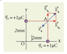
The acceleration experienced by an electron placed at point A is
\(\vec { a_{ A } } =\frac { \vec { F } }{ m } =\frac { q\vec { { E }_{ A } } }{ m } \)
=\(\frac { (-1.6\times 10^{ -19 })\times (2.25\times 10^{ 9 })(\hat { i } +\hat { j } ) }{ 9.1\times { 10 }^{ -31 } } \)
= -3.95 x 10²⁰ \((\hat { i } +\hat { j } )\)Nkg-1
The electron is accelerated in a direction exactly opposite to \(\vec { { E }_{ A } } \).
9.
(c)
become more than double
10.
(c)
thermionic
11.
\(K .E_{\max } =\mathrm{hv}-\phi \)
\(=\frac{\mathrm{hc}}{\lambda}-\phi \)
\(\mathrm{E} =\frac{6.6 \times 10^{-34} \times 3 \times 10^8-1.235}{500 \times 10^{-9} \times 1.6 \times 10^{-19}} \)
\(=2.475-1.235 \)
\(\text {K. } \mathrm{E}_{\max } =1.24 \mathrm{eV}\)
12.
\(\mathrm{P} =\frac{\mathrm{n}}{\mathrm{t}} \frac{\mathrm{hc}}{\lambda} \)
\(\frac{\mathrm{n}}{\mathrm{t}} =\frac{\mathrm{P} \lambda}{\mathrm{hc}} \)
\(\frac{\mathrm{n}}{\mathrm{t}} =\frac{3.8 \times 10^{26} \times 550 \times 10^{-9}}{6.6 \times 10^{-3} \times 3 \times 10^8}=1 \times 10^{-15}\)
13.
\(\frac{\mathrm{hc}}{\lambda} =\phi+\mathrm{K} . \mathrm{E} .....(1) \)
\(\frac{2 \mathrm{hc}}{\lambda} =\phi+3 \mathrm{~K} . \mathrm{E}......(2)\)
multiply eqn. (1) by 3, we get
\(\frac{3 \mathrm{hc}}{\lambda} =3\phi+3 \mathrm{~K} . \mathrm{E} .....(3)\)
Subtract eqn. (2) from (3), we get
\(\frac{\mathrm{hc}}{\lambda} =2\phi \)
\(\phi=\frac{ \mathrm{hc}}{2\lambda} \)
14.
\(\lambda\propto \frac{1}{\sqrt{V}}\)
\(\frac{\lambda_1}{\lambda_2}=\frac{\sqrt{224\times10^3}}{\sqrt{14\times 10^3}}\)
\(=\sqrt{16}=4\)
\(\lambda_{\mathrm{2}}= \frac{\lambda_1}{4}\)
15.
\(\mathrm{E}_{\mathrm{p}} =\frac{\mathrm{hc}}{\lambda_{\mathrm{p}}} \)
\(\mathrm{E}_{\mathrm{e}} =\frac{\mathrm{h}^2}{2 \mathrm{~m} \lambda_{\mathrm{e}}^2} \)
\(\frac{\mathrm{hc}}{\lambda_{\mathrm{p}}} =\frac{\mathrm{h}^2}{2 \mathrm{~m} \lambda_{\mathrm{e}}^2} \)
\(\lambda_{\mathrm{p}} \propto \lambda_{\mathrm{e}}^{{ }^2}\)
16.
(b)
Newton's II law
17.
Q = q1 + q2 = 4 x 10⁻²C
\(q_{2f}=Q[\frac{r_2}{r_1+r_2}]\)
= 4 x 10⁻² \([\frac{3}{4}]\)
q2f = 3 x 10⁻² C
18.
Energy density uE \(=\frac{U}{volume}\)
If A' = 2A d ' = 2d
Then V ' = 2A x 2d = 4Ad = 4V
Then volume would be increased. So, energy density will change.
19.
If voltage is increased from V to 2 V
Then Q1 = CV
Q2 = C(2 V) = 2 CV
∴ Q is doubled and C remains same
20.
\(\vec {E}\) = 10x\(\hat{i},\) when x = 2 m
\(\vec {E}\) = 10 x 2 x \(\hat{i}\) = 20\(\hat{i}\)
Since, \(E=\frac{-dV}{dx}\therefore V=+20 V\)
21.
Force ∝ charge
After the separation, the magnitude of charge will be increased. So the force will be more than before.
22.
(b)
23.
The charge + q will be stable between B1 and B2 with respect to the displacement.
24.
Davisson - Germer experiment
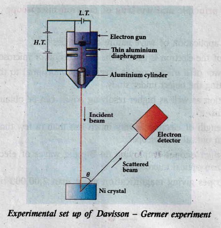
(i) The filament F is heated by a low tension (L . T) battery. Electrons are emitted from the hot filament by thermionic emission.
(ii) They are then accelerated due to the potential diference between the filament and the anode aluminum cylinder by a high tension (H.T) battery.
(iii) Electron beam is collimated by using two thin aluminum diaphragms and is allowed to strike a single crystal of Nickel.
(iv) The electrons scattered by Niatoms in diflerent directions are received by the electron detector which measures the intensity of scattered electron beam.
(v) The detector is capable of rotation in the plane of the paper, so that the angle (\(\theta\)) between the incident beam and the scattered beam can be changed at our will.
(vi) The intensity of the scattered electron beam is measured as a function of the angle \(\theta\).
(i) Figure shows the variation of intensity of the scattered electrons with the angle \(\theta\) for the accelerating voltage of 54 V.
(ii) For a given accelerating voltage V, the scattered wave shows a peak or maximum at an angle of 50o to the incident electron beam.
(iii) This peak in intensity is attributed to the constructive interference of electrons diffracted from various atomic layers of the target material.
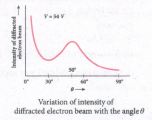
(iv) From the known value of interplanar spacing of Nickel, the wavelength of the electron wave has been experimentally calculated as 1.65\(\overset { o }{ A }\).
(v) The wavelength can also be calculated from de Broglie relation for V = 54 V from equation as
\(\lambda =\cfrac { 12.27 }{ \sqrt { V } } \overset { o }{ A } =\cfrac { 12.27 }{ \sqrt { 54 } } \)
\(\lambda =1.67\overset { o }{ A } \)
(vi) This value agrees very well with the experimentally observed wavelength of 1.65 \(\overset { o }{ A }\). Thus this experiment directly verifies de Broglie's hypothesis of the wave nature of moving particles.
25.
Principle:
(i) The wave nature of the electron is used in the construction of microscope called electron microscope.
(ii)The resolving power of a microscope is inversely proportional to the wavelength of the radiation used for illuminating the object under study.
(iii) Higher magnification as well as higher resolving power can be obtained by employing the waves of shorter wavelengths.
(iv) De Broglie's wavelength of electron is very much less than (a few thousand less) that of the visible light being used in optical microscopes.
(v) As a result, the microscopes employing de Broglie waves of electrons have very much higher resolving power than optical microscope.
(vi) Electron microscopes giving magnification more than 2,00,000 times are common in research laboratories.
Working:
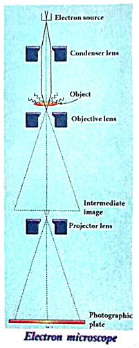
(i) The construction and working of an electron microscope is similar to that of an optical microscope except that in electron microscope focussing of electron beam is done by the electrostatic or magnetic lenses.
(ii) The electron beam passing across a suitably arranged either electric or magnetic fields undergoes divergence or convergence thereby focussing of the beam is done.
(iii) The electrons emitted from the source are accelerated by high potentials.
(iv) The beam is made parallel by magnetic condenser lens; When the beam passes through the sample whose magnified image is needed, the beam carries the image of the sample.
(v) With the help of magnetic objective lens and magnetic projector lens system, the magnified image is obtained on the screen. These electron microscopes are being used in almost all brands of science.
26.
(i) In metals, the electrons in the outer most shells are loosely bound to the nucleus. Even at room temperature, there are a large number of free electrons which are moving inside the metal in a random manner. Through they move freely inside the metal they cannot leave the surface of the metal. The reason is that when free electrons reach the surface of the metal they are attracted by the positive nuclei of the metal. It is attractive pull which will not allow free electrons to leave the metallic surface at room temperature.
(ii) In order to leave the metallic surface, the free electrons must cross a potential barrier created by the positive nuclei of the metal. The potential barrier. which prevents free electrons from leading the metallic surface is called surface barrier.
(iii) Whenever an additional energy is given to the free electrons, they will have sufficient energy to cross the surface barrier. And they escape from the metallic surface. The liberation of electrons from any surface of a substance is called electron emission.
(iv) The minimum energy needed for an electron to escape from the metal surface is called work function of that metal.
(a) Thermionic emission
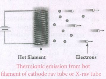
(i) When a metal is heated to a high temperature, the free electrons on the surface of the metal get sufficient energy in the form of thermal energy so that they are emitted from the metallic surface. This type of emission is known a thermonic emission.
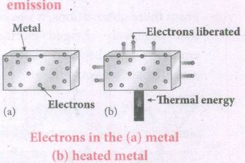
(ii) The intensity of the thermionic emission (the number of electrons emitted) depends on the metal used and its temperature.
(iii) Examples: cathode ray tubes, electron microscopes, X-ray tubes etc.
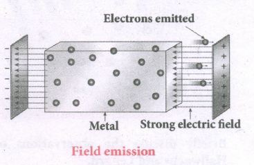
(b) Field emission
(i) Electric field emission occurs when a very strong electric field is applied across the metal.
(ii) This strong field pulls the free electrons and helps them to overcome the surface barrier of the metal.
(iii) Ex: Field ermssion scanning electron microscopes, Field-emission display etc.
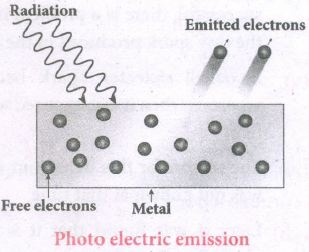
(c) Photo electric emission
(i) When an electromagnetic radiation of suitable frequency is incident on the surface of the metal, the energy is transferred from the radiation to the free electrons.
(ii) Hence, the free electrons get sufficient energy to cross the surface barrier and the photo electric emission takes place.
(iii) The number of electrons emitted depend on the intensity of the incident radiation.
(iv) Examples: Photo diodes, photo electric cells etc.
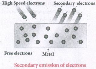
(d) Secondary emission
(i) When a beam of fast-moving electrons strikes the surface of the metal, the kinetic energy of the striking electrons is transferred to the free electrons on the metal surface.
(ii) Thus the free electrons get sufficient kinetic energy so that the secondary emission of electron occurs.
(iii) Examples: Image intensifiers, photo multiplier tubes etc.
27.
(a) Capacitor in series
(i) Consider three capacitors of capacitance C1, C2 and C3 connected in series with a battery of voltage V as shown in the Figure (a).
(ii) As soon as the battery is connected to the capacitors in series, the electrons of charge -Q are transferred from negative terminal to the right plate of C3 which pushes the electrons of same amount -Q from left plate of C3 to the right plate of C2 due to electrostatic induction.
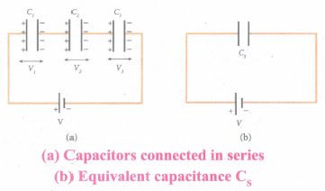
(iii) Similarly, the left plate of C2 pushes the charges of -Q to the right plate of C1 which induces the positive charge +Q on the left plate of C1.
(iv) At the same time, electrons of charge -Q are transferred from left plate of C1 to positive terminal of the battery.
(v) By these processes, each capacitor stores the same amount of charge Q.
(vi) The capacitances of the capacitors are in general different so that the voltage across each capacitor is also different and are denoted as V1, V2 and V3 respectively.
(vii) The sum voltage across capacitor must be equal to the voltage of the battery.
V = V1 + V2 + V3 ....(1)
Since, Q = CV
We have V = \(\frac { Q }{ { C }_{ 1 } } +\frac { Q }{ { C }_{ 2 } } +\frac { Q }{ { C }_{ 3 } } \)
\(=Q\left[ \frac { 1 }{ { C }_{ 1 } } +\frac { 1 }{ { C }_{ 2 } } +\frac { 1 }{ { C }_{ 3 } } \right] ...(2)\)
(viii) If three capacitors in series are considered to form an equivalent single capacitor Cs shown in Figure (b), then we have \(V=\frac { Q }{ { C }_{ s } } \). Substituting this expression into equation (2), we get
\(\frac { Q }{ { C }_{ s } } =Q\left( \frac { 1 }{ { C }_{ 1 } } +\frac { 1 }{ { C }_{ 2 } } +\frac { 1 }{ { C }_{ 3 } } \right) \)
\(\frac { 1 }{ { C }_{ s } } =\frac { 1 }{ { C }_{ 1 } } +\frac { 1 }{ { C }_{ 2 } } +\frac { 1 }{ { C }_{ 3 } } \) ...(3)
(ix) Thus, the inverse of the equivalent capacitance Cs of three capacitors connected in series is equal to the sum of the inverses of each capacitance. This equivalent capacitance Cs, is always less than the smallest individual capacitance in the series.
(b) Capacitor in parallel
i) Consider three capacitors of capacitance C1, C2 and C3 connected in parallel with a battery of voltage V as shown in Figure (a).
ii) Since corresponding sides of the capacitors are connected to the same positive and negative terminals of the battery, the voltage across each capacitor is equal to the battery's voltage.
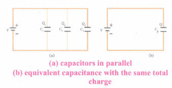
iii) Since capacitance of the capacitors is different, the charge stored in each capacitor is not the same. Let the charge stored in the three capacitors be Q1, Q2, and Q3 respectively.
iv) According to the law of conservation of total charge, the sum of these three charges is equal to the charge Q transferred by the battery,
Q = Q1 + Q2 + Q3 ...(4)
Now, since Q = CV, we have
Q = C1V + C2V + C3V ...(5)
(v) If these three capacitors are considered to form a single capacitance C, which stores the total charge Q as shown in the Figure (b), then we can write Q = CpV. Substituting this in equation (2), we get
CpV = C1V + C2V + C3V
Cp = C1+ C2 + C3 ...(6)
vi) Thus, the equivalent capacitance of capacitors connected in parallel is equal to the sum of the individual capacitances.
vii) The equivalent capacitance Cp, in a parallel connection is always greater than the largest individual capacitance. In a parallel connection, it is equivalent as area of each capacitance adds to give more effective area such that total capacitance increases.
28.
Effect of dielectrics in capacitors:
Suppose dielectrics like mica, glass or paper are introduced between the plates, then the capacitance of the capacitor is altered. The dielectric can be inserted into the plates in two different ways.
(i) when the capacitor is disconnected from the battery.
(ii) when the capacitor is connected to the battery.
(i) When the capacitor is disconnected from the battery
Consider a capacitor with two parallel plates each of cross-sectional area A and are separated by a distance d. The capacitor is charged by a battery of voltage Vo and the charge stored is Qo. The capacitance of the capacitor without the dielectric is,
\(C_{0}=\frac{Q_{0}}{V_{0}}\) ....(i)
The battery is then disconnected from the capacitor and the dielectric is inserted between the plates. This is shown in Figure.
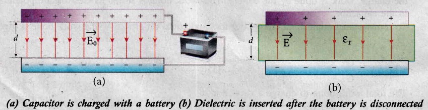
The introduction of dielectric between the plates will decrease the electric field. Experimentally it is found that the modified electric field is given by,
\(E=\frac{E_{0}}{\varepsilon_{r}}\) ....(2)
Here Eo is the electric field inside the capacitors when there is no dielectric and \(\varepsilon_{\mathrm{r}}\) is the relative permittivity of the dielectric or simply known as the dielectric constant. Since \(\varepsilon_{\mathrm{r}}\) > 1, the electric field E < Eo.
As a result, the electrostatic potential difference between the plates (V = Ed) is also reduced. But at the same time, the charge Qo will remain constant once the battery is disconnected.
Hence the new potential difference is
\(V=E d=\frac{E_{0}}{\varepsilon_{r}} d=\frac{V_{0}}{\varepsilon_{r}}\) .......(3)
We know that capacitance is inversely proportional to the potential difference. Therefore as V decreases, C increases.
Thus new capacitance in the presence of a dielectric is
\(C=\frac{Q_{0}}{V}=\varepsilon_{r} \frac{Q_{0}}{V_{0}}=\varepsilon_{r} C_{0}\) ......(4)
Since \(\varepsilon_{\mathrm{r}}\) > 1, we have C > Co. Thus insertion of the dielectric increases the capacitance.
We know that, Co =\(\frac{\varepsilon_{\mathrm{o}} A}{d}\) ...........(5)
Equation (4) ⇒ \(C=\frac{\varepsilon_{r} \varepsilon_{0} A}{d}=\frac{\varepsilon A}{d} \) ..........(6)
where \(\varepsilon=\varepsilon_{\mathrm{r}} \varepsilon_{\mathrm{o}}\) is the permittivity of the dielectric medium.
The energy stored in the capacitor before the insertion of a dielectric is given by,
\(U_{0}=\frac{1}{2} \frac{Q_{0}^{2}}{C_{0}}\) .......(7)
After the dielectric is inserted, the charge Qo remains constant but the capacitance is increased. As a result, the stored energy is decreased.
\(U=\frac{1}{2} \frac{Q_{0}^{2}}{C}=\frac{1}{2} \frac{Q_{0}^{2}}{\varepsilon_{r} C_{0}}=\frac{U_{0}}{\varepsilon_{r}}\) ..........(8)
Since \(\varepsilon_{\mathrm{r}}\) > 1we get U < Uo. There is a decrease in energy because, when the dielectric is inserted, the capacitor spends some energy in pulling the dielectric inside.
(ii) When the battery remains connected to the capacitor:
When the battery of voltage vo remains connected to the capacitor and the dielectric is inserted into the capacitor, then
(a) The potential difference vo across the plates remains constant.
(b) The charge stored in the capacitor is increased by a factor \(\varepsilon_{\mathrm{r}}\). (Experimentally found).
.jpg)
\({Q}=\varepsilon_{r} Q_{0}\) .......(1)
Due to this increased charge, the capacitance is also increased. The new capacitance is,
\(C=\frac{Q}{V_{0}}=\varepsilon_{r} \frac{Q_{0}}{V_{0}}=\varepsilon_{r} C_{0}\) ......(2)
However the reason for the increase in capacitance in this case where the battery remains connected is different from the case when the battery is disconnected before introducing the dielectric.
The energy stored in the capacitor before the insertion of a dielectric is given by,
\(U_{0}=\frac{1}{2} C_{0} V_{0}^{2}\) ....(4)
After the dielectric is inserted, the capacitance is increased; hence the stored energy is also increased.
\( U=\frac{1}{2} C V_{0}^{2}=\frac{1}{2} \varepsilon_{r} C_{0} V_{0}^{2}=\varepsilon_{r} U_{0} \) .....(5)
\(Since \ \varepsilon_{r}>1\ we \ have \ U>U_{o}.\)
Note: Here we have not used the expression \(U_o=\frac{1}{2}\frac{Q_0^2}{C_0}\)because here, both charge and capacitance are changed, whereas in equation (4), Vo remains constant.
Since voltage between the capacitor Vo is constant, the electric field between the plates also remains constant .The energy density is given by,
\(u=\frac{1}{2} \varepsilon E_{0}^{2}\) ..(6)
where ε is the permittivity of the given dielectric material.
29.
Case (i): Electric field due to an electric dipole at points on the axial Iine:
Consider an electric dipole placed on the x-axis as shown in Figure. A point C is located at a distance of r from the midpoint O (of the dipole) along the axial line.
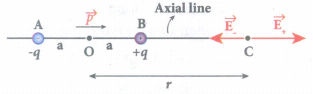
The electric field at a point C due to +q is
\({ \vec { E } }_{ + }=\frac { 1 }{ 4\pi { \varepsilon }_{ 0 } } \frac { q }{ { (r-a) }^{ 2 } } \) along BC
Since the electric dipole moment vector \(\vec { p } \) is from -q to +q and is directed along BC, the above equation is rewritten as
\({ \vec { E } }_{ + }=\frac { 1 }{ 4\pi { \varepsilon }_{ 0 } } \frac { q }{ { (r-a) }^{ 2 } } \hat { p } \) ....(1)
When \(\vec { p } \) is the electric dipole moment unit vector from -q to +q. The electric field at a point C due to -q is
\({ \vec { E } }_{ - }=-\frac { 1 }{ 4\pi { \varepsilon }_{ 0 } } \frac { q }{ { (r+a) }^{ 2 } } \hat { p } \) ....(2)
Since +q is located closer to the point C than -q, \({ \vec { E } }_{ + }\) is stronger than \({ \vec { E } }_{ - }\). Therefore, the length of the \({ \vec { E } }_{ + }\) vector is drawn larger than that of \({ \vec { E } }_{ - }\) vector.
The total electric field at point C is calculated using the superposition principle of the electric field.
\({ \vec { E } }_{ tot }={ \vec { E } }_{ + }+{ \vec { E } }_{ - }\)
\(=\frac { 1 }{ 4\pi { \varepsilon }_{ 0 } } \frac { q }{ { (r-a) }^{ 2 } } \hat { p } -\frac { 1 }{ 4\pi { \varepsilon }_{ 0 } } \frac { q }{ { (r+a) }^{ 2 } } \hat { p } \)
\({ \vec { E } }_{ tot }=\frac { q }{ 4\pi { \varepsilon }_{ 0 } } \left( \frac { 1 }{ { (r-a) }^{ 2 } } -\frac { 1 }{ { (r+a) }^{ 2 } } \right) \hat { p } \) ....(3)
\({ \vec { E } }_{ tot }=\frac { 1 }{ 4\pi { \varepsilon }_{ 0 } } q\left( \frac { 4ra }{( { r }^{ 2 }-{ a }^{ 2 })^2 } \right) \hat { p } \) ...(4)
Note that the total electric field is along \({ \vec { E } }_{ + }\), since +q is closer to C than -q.
If the point C is very far away from the dipole then (r >> a). Under this limit the term \(({ r }^{ 2 }-{ a }^{ 2 })\approx { r }^{ 2 }\).
Substituting this into equation (4), we get
\({ \vec { E } }_{ tot }=\frac { 1 }{ 4\pi { \varepsilon }_{ 0 } } \left( \frac { 4aq }{ { r }^{ 3 } } \right) \hat { p } (r>>a)\)
\(since\quad 2aq\hat { p } =\vec { p } \)
\({ \vec { E } }_{ tot }=\frac { 1 }{ 4\pi { \varepsilon }_{ 0 } } \frac { 2\vec { p } }{ { r }^{ 3 } } (r>>a)\) ...(5)
The direction \({ \vec { E } }_{ tot }\) is shown in Figure.
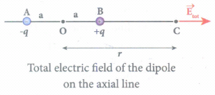
NOTE: If the point C is chosen on the left side of the dipole, the total electric field is still in the direction of \(\vec { p } \).
Case (ii) Electic field due to an electric dipole at a point on the equatorial plane:
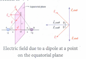
Consider a point C at a distance r from the midpoint O of the dipole on the equatorial plane. Since the point C is equidistant from +q and -q, the magnitude of the electric fields of +q and -q are the same. The direction of \({ \vec { E } }_{ + }\) is along BC and the direction of \({ \vec { E } }_{ - }\) is along CA. \({ \vec { E } }_{ + }\) and \({ \vec { E } }_{ - }\) are resolved into two components; one component parallel to the dipole axis and the other perpendicular to it. The perpendicular components \(|{ \vec { E } }_{ + }|\) sinθ and \(|{ \vec { E } }_{ -}|\) sinθ are equal in magnitude and oppositely directed and cancel each other. The magnitude of the total electric field at point C is the sum of the parallel components of \({ \vec { E } }_{ + }\) and \({ \vec { E } }_{ - }\) and its direction is along \(-\hat{p}\) as shown in the Figure.
\({ \vec { E } }_{ tot }=-|{ \vec { E } }_{ + }|cos\theta \hat { p } -|{ \vec { E } }_{ - }|cos\theta \hat { p } \) ...(6)
The magnitudes \({ \vec { E } }_{ + }\) and \({ \vec { E } }_{ - }\) are the same and given by,
\(|{ \vec { E } }_{ + }|=|{ \vec { E } }_{ - }|=\frac { 1 }{ 4\pi { \varepsilon }_{ 0 } } \frac { q }{ (r^2+a^2) } \) ...(7)
By substituting equation (7) into equation (6), we get
\({ \vec { E } }_{ tot }=\frac { 1 }{ 4\pi { \varepsilon }_{ 0 } } \frac { 2qcos\theta }{ ({ r }^{ 2 }+{ a }^{ 2 }) } \hat { p } ....(8)\)
\(=-\frac { 1 }{ 4\pi { \varepsilon }_{ 0 } } \frac { 2qa }{ ({ r }^{ 2 }+{ a }^{ 2 })^{ \frac { 3 }{ 2 } } } \hat { p } \)
Since \(cos \theta =\frac { a }{ \sqrt { { r }^{ 2 }+{ a }^{ 2 } } } \)
\({ \vec { E } }_{ tot }=\frac { 1 }{ 4\pi { \varepsilon }_{ 0 } } \frac { \vec { p } }{ ({ r }^{ 2 }+{ a }^{ 2 })^{ \frac { 3 }{ 2 } } } \)
Since \(\vec { p } \) = 2qa\(\hat { p } \) ...(9)
At very large distances (r >> a), the equation (9) becomes
\({ \vec { E } }_{ tot }=\frac { 1 }{ 4\pi { \varepsilon }_{ 0 } } \frac { \vec { p } }{ { r }^{ 3 } } (r>>a)\) ...(10)
Negative sign shows that direction of Electric field is opposite to the direction of dipole moment vector.
30.
(i) In photo emissive cell emission of electrons from a metal cathode is due to irradiation of light or other radiations.
(ii) In photo voltaic cell, sensitive element made of semiconductor is used which generates voltage proportional to the intensity of light or other radiations.
(iii) In photo conductive cell, the resistance of the semiconductor charges in accordance with the radiant energy incident on it.
31.
There is a smallest value of frequency for which the incident light can eject the photo electrons out of the metal. Light of frequencies smaller than vo cannot eject photoelectrons, no matter how much high is its intensity, Such a frequency is called 'threshold frequency' or 'critical frequency'.
32.
The high voltage in Van de Graaff generator is used to accelerate protons and deuterons for the nuclear disintegrations and other applications.
33.
The electric field due to a collection of point charges at an arbitrary point is simply equal to the vector sum of the electric fields created by the individual point charges. This is called superposition principle of electric fields.
34.
(i) Photo cells are used as switches and sensors.
(ii) Automatic switch on and off of street lights.
(iii) They are used for reproduction of sound in motion pictures
(iv) They are used as timers to measure the speed of athletes during a race.
(v) In photography, they are used to measure the intensity of the given light and to calculate the exact time of exposure.
35.
Laws of photoelectric effect:
(i) For a given surface, the emission of photoelectrons takes place only if the frequency of incident light is greater than a certain minimum frequency called the threshold frequency.
(ii) For a given frequency of incident light, the number of photoelectrons emitted is directly proportional to the intensity of the incident light. The saturation current is also directly proportional to the intensity of incident light.
(iii) Maximum kinetic energy of the photoelectrons is independent of the intensity of the incident light.
(iv) Maximum kinetic energy of the photoelectrons from a given metal is directly proportional to the frequency of incident light.
(v) There is no time lag between the incidence of light and the ejection of photoelectrons.
36.
An alpha particle contains 2 protons and 2 neutrons. Therefore, the mass M of the alpha particle is 4 times that of a proton (mp) (or a neutron) and its charge q is twice that of a proton (+e).
The de Broglie wavelength associated with it is
\(\lambda=\frac { h }{ \sqrt { 2MqV } } =\frac { h }{ \sqrt { 2\times (4m_{ p })\times (2e)\times V } } \)
\(=\frac { 6.626\times { 10 }^{ -34 } }{ \sqrt { 2\times 4\times 1.67\times 10^{ -27 }\times 2\times 1.6\times { 10 }^{ -19 }\times 400 } } \)
\(=\frac { 6.626\times 10^{ -34 } }{ 4\times 20\times { 10 }^{ -23 }\sqrt { 1.67\times 1.6 } } \) = 0.00507 \(\mathring { A }\)
37.
Energy stored in the capacitor
i) Capacitor not only stores the charge but also it stores energy. When a battery is connected to the capacitor, electrons of total charge - Q are transferred from one plate to the other plate. To transfer the charge, work is done by the battery. This work done is stored as electrostatic potential energy in the capacitor.
ii) To transfer an infinitesimal charge dQ for a potential difference V, the work done is given by
dW = V dQ
Where \(V=\frac { Q }{ C } \) .....(1)
iii) The total work done to charge a capacitor is
\(W=\int _{ 0 }^{ Q }{ \frac { Q }{ C } } dQ=\frac { { Q }^{ 2 } }{ 2C } \quad \quad ....(2)\)
This work done is stored as electrostatic potential energy (UE) in the capacitor.
\({ U }_{ E }=\frac { { Q }^{ 2 } }{ 2C } =\frac { 1 }{ 2 } { CV }^{ 2 },\quad (\therefore Q=CV)\quad ....(3)\)
(iv) This stored energy is thus directly proportional to the capacitance of the capacitor and the square of the voltage between the plates of the capacitor.Substituting \(C=\frac { { \varepsilon }_{ 0 }A }{ d } \) and V = Ed.
\(U=\frac { 1 }{ 2 } \left( \frac { { \varepsilon }_{ 0 }A }{ d } \right) { (Ed) }^{ 2 }=\frac { 1 }{ 2 } { \varepsilon }_{ 0 }(Ad){ E }^{ 2 }\quad \quad \quad \quad \quad ...(4)\)
where Ad = volume of the space between the capacitor plates. The energy stored per unit volume of space is defined as energy density \({ u }_{ E }=\frac { U }{ Volume } \)
Equation (4) ⇒ \({ u }_{ E }=\frac{1}{2}{ \varepsilon }_{ 0 }{ E }^{ 2 }\).....(5)
(v) From equation (5),
(a) We infer that the energy is stored in the electric field existing between the plates of the capacitor. Once the capacitor is allowed to discharge, the energy is retrieved.
(b) The energy density depends only on the electric field and not on the size of the plates of the capacitor.
(c) This is true for the electric field due to any type of charge configuration.
38.
Electric potential due to a point charge:
Consider a positive charge q kept fixed at the origin. Let P be a point at distance r from the charge q. This is shown in Figure.
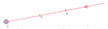
Electrostatic potential at a point P
The electric potential at the point P is
\(V=\int _{ \infty }^{ r }{ \left( -\vec { E } \right) d\vec { r } } =-\int _{ \infty }^{ r }{ \vec { E } } .d\vec { r } \) ...(1)
Electric field due to positive point charge q is
\(\vec { E } =\frac { 1 }{ 4\pi { \varepsilon }_{ 0 } } \frac { q }{ { r }^{ 2 } } \hat { r } \)
\(V=\frac { -1 }{ 4\pi { \varepsilon }_{ 0 } } \int _{ \infty }^{ r }{ \frac { q }{ { r }^{ 2 } } \hat { r } .d\vec { r } } \)
The infinitesimal displacement vector, \(d\vec { r } =dr\hat { r } \) and using \(\hat { r } \).\(\hat { r } \) = 1, we have
\(V=\frac { 1 }{ 4\pi { \varepsilon }_{ 0 } } \int _{ \infty }^{ r }{ \frac { q }{ { r }^{ 2 } } \hat { r } .dr\hat { r } =\frac { 1 }{ 4\pi { \varepsilon }_{ 0 } } \int _{ \infty }^{ r }{ \frac { q }{ { r }^{ 2 } } dr } } \)
After the integration,
\(V=-\frac { 1 }{ 4\pi { \varepsilon }_{ 0 } } q{ \left\{ -\frac { 1 }{ r } \right\} }_{ \infty }^{ r }=\frac { 1 }{ 4\pi { \varepsilon }_{ 0 } } \frac { q }{ r } \)
Hence, the electric potential due to a point charge q at a distance r is
\(V=\frac { 1 }{ 4\pi { \varepsilon }_{ 0 } } \frac { q }{ r } \) ....(2)

12th Standard Syllabus & Materials
12th Standard
TN 12th Computer Applications வலையமைப்பு வடமிடல் Sample Question Papers Study Material - QB365 Set A
NEW12th Standard
TN 12th Computer Applications களப்பெயர் முறைமை (DNS) Sample Question Papers Study Material - QB365 Set A
NEW12th Standard
TN 12th Computer Applications வலையமைப்பு எடுத்துக்காட்டுகள் மற்றும் நெறிமுறைகள் Sample Question Papers Study Material - QB365 Set A
NEW12th Standard
TN 12th Computer Applications கணினி வலையமைப்பு ஓர் அறிமுகம் Sample Question Papers Study Material - QB365 Set A



Tamilnadu Stateboard 12th Standard Subjects

Maths

Chemistry
Physics

Biology

Computer Science

Business Maths and Statistics

Economics

Commerce

Accountancy

History

Computer Applications
Biology
Computer Technology
Computer Applications
Computer Science
Business Maths and Statistics
Commerce
Economics
Maths
Chemistry
Physics
Computer Technology
History
Accountancy

Tamil

English

French
Tamilnadu Stateboard Standards


