
 100% FREE ACCESS
12th Standard Syllabus & Materials
12th Standard
TN 12th Computer Applications மின்னணு தரவு பரிமாற்றம் Sample Question Papers Study Material - QB365 Set A
NEW12th Standard
TN 12th Computer Applications மின் - வணிக பாதுகாப்பு அமைப்புகள் Sample Question Papers Study Material - QB365 Set A
NEW12th Standard
TN 12th Computer Applications மின்னணு செலுத்தல் முறைகள் Sample Question Papers Study Material - QB365 Set A
NEW12th Standard
TN 12th Computer Applications மின் - வணிகம் Sample Question Papers Study Material - QB365 Set A
NEW12th Standard
TN 12th Computer Applications திறந்த மூல கருத்துருக்கள் Sample Question Papers Study Material - QB365 Set A
NEW12th Standard
TN 12th Computer Applications வலையமைப்பு வடமிடல் Sample Question Papers Study Material - QB365 Set A

Published on: 28/11/2025
Download Tamil Nadu 12th Standard Physics question papers, model tests, one-mark questions, important questions, and public exam papers in PDF format. Free study materials and answer keys for TN State Board students.
Questions + Answers key
Take MCQ Physics Test
1.
A proton and an electron have same kinetic energy. Which one has greater de Broglie wavelength. Justify.
2.
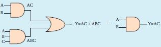
Prove the Boolean identity AC + ABC = AC and give its circuit description.
3.
The wavelength of a light is 450 nm. How much phase it will differ for a path of 3 mm?
4.
If the focal length is 150 cm for a lens, what is the power of the lens?
5.
Calculate the radius of \(_{ 79 }^{ 197 }{ Au }\) Au nucleus.
6.
Suppose a cyclotron is operated to accelerate protons with a magnetic field of strength 1 T. Calculate the frequency in which the electric field between two Dees could be reversed.
7.
A square coil of side 30 cm with 500 turns is kept in a uniform magnetic field of 0.4 T. The plane of the coil is inclined at an angle of 30o to the field. Calculate the magnetic flux through the coil.
8.
The relative magnetic permeability of the medium is 2.5 and the relative electrical permittivity of the medium is 2.25. Compute the refractive index of the medium.
9.
10.
Resistance of a material at 20oC and 40oC are 45 Ω and 85 Ω respectively. Find its temperature coefficient of resistivity.
11.
Photon carries _______
energy
mass
volume
electrons
12.
How many NAND gates are used to form AND gate ____________.
1
2
3
4
13.
The blue print for making ultra durable synthetic material is mimicked from _____.
Lotus leaf
Morpho butterfly
Parrot fish
Peacock feather
14.
The work functions for metals A, B and C are 1.92 eV, 2.0 eV and 5.0 eV respectively. The metal/metals which will emit photoelectrons for a radiation of wavelength 4100 Å is/are _____.
A only
both A and B
all these metals
none
15.
The radius of curvature of curved surface at a thin planoconvex lens is 10 cm and the refractive index is 1.5. If the plane surface is silvered, then the focal length will be, ______.
5 cm
10 cm
15 cm
20 cm
16.
An example for a Non-polar molecule is ____________.
H2O
N2O
CO2
NH3
17.
A circular coil of radius 5 cm and 50 turns carries a current of 3 ampere. The magnetic dipole moment of the coil is nearly ____.
1.0 A m2
1.2 A m2
0.5 A m2
0.8 A m2
18.
19.
20.
The internal resistance of a 2.1 V cell which gives a current of 0.2 A through a resistance of 10 Ω is ______.
0.2 Ω
0.5 Ω
0.8 Ω
1.0 Ω
21.
22.
Describe the function of a transistor as an amplifier with the neat circuit diagram. Sketch the input and output wave forms.
23.
Discuss the diffraction at a grating and obtain the condition for the mth maximum.
24.
Explain the ampitude modulation with necessary diagrams.
25.
Derive the equation for refraction at single spherical surface.
26.
Explain the J.J. Thomson experiment to determine the specific charge of electron.
27.
Discuss the conversion of galvanometer into an ammeter and also a voltmeter.
28.
Explain the construction and working of transformer.
29.
Calculate the electric field due to a dipole on its axial line and equatorial plane.
30.
Explain the determination of unknown resistance using meter bridge.
1.
The de Broglie wavelength associated with the kinetic energy K is \(\lambda=\frac{h}{\sqrt{2 m k}}\)
Where m is the mass of the particle
Since proton and electron have same KE, the wavelength is inversely proportional to square root of the mass \(\lambda \alpha \frac{1}{\sqrt{m}}\)
Mass of proton is 1840 times greater them that of electron. Therefore, de Broglie's wavelength of electron is greater than the proton.
2.
Step 1: AC (1 + B) = AC.1 [OR law-2]
Step 2: AC . 1 = AC [AND law – 2]
Therefore, AC + ABC = AC
Thus the Boolean identity is proved.
Circuit Description
3.
Wavelength is, λ = 450 nm = 450 x 10-9m
Path difference is, ઠ = 3mm = 3 x 10⁻³m
Relation between phase difference and path difference is \(\phi =\cfrac { 2\pi }{ \lambda } \times \delta \)
Substituting,
\(\phi =\cfrac { 2\pi }{ 450\times { 10 }^{ -9 } } \times 3\times { 10 }^{ -3 }=\cfrac { \pi }{ 75 } \times { 10 }^{ 6 }\)
\(\phi=\frac{\pi}{75} \times 10^{6} \mathrm{rad}=4.19 \times 10^{4} \mathrm{rad}.\)
4.
Given, focal length, f = 150 cm = 1.5 m
Equation for power of lens is, \(p=\cfrac { 1 }{ f } \)
Substituting the values,
\(p=\cfrac { 1 }{ 1.5 } =0.67 D\)
As the power is positive, it is a converging lens.
5.
R = R0A\(\frac13\)
R = 1.2 x 10−15 x (197)\(\frac13\) = 6.97 x 10⁻¹⁵ m
Or R = 6.97 F
6.
Magnetic field B = 1 T
Mass of the proton, mp = 1.67 x 10⁻²⁷kg
Charge of the proton, q = 1.60 x 10⁻¹⁹C
\(f=\frac { qB }{ { { 2\pi m }_{ p } } } =\frac { \left( 1.60\times { 10 }^{ -19 } \right) \left( 1 \right) }{ 2\left( 3.14 \right) \left( 1.67\times { 10 }^{ -27 } \right) } \)
= 15.3 x 10⁶ Hz = 15.3 MHz
7.
Number of turns, N = 500
Area of cross section, A = 30 x 30 x 10-4
= 900 x 10-4 m2
Magnetic field, B = 0.4 T
Angle of inclination θ = 900 - 300= 600
∴ Magnetic flux Φ = NAB cos θ
∴ Φ = 500 x 900 x 10-4 x 0.4 x cos600
= 45 x 104 x 10-4 x 4 x 10-1 x \(\frac{1}{2}\)
Φ= 9 x 10-1 = 9.0 Wb
∴ Magnetic flux Φ = 9.0 Wb
8.
Dielectric constant (relative permittivity of the medium) is εr = 2.25
Magnetic permeability is μr = 2.5
Refractive index of the medium,
n = \(\sqrt { { \varepsilon }_{ r }{ \mu }_{ r } } =\sqrt { 2.25\times 2.5 } \) = 2.37
9.
10.
T0 = 20oC, T = 40oC, Ro = 45 Ω , R = 85 Ω
\(\alpha =\frac { 1 }{ { R }_{ 0 } } \frac { \Delta R }{ \Delta T } \)
\(\alpha=\frac{1}{45}\left(\frac{85-45}{40-20}\right)=\frac{1}{45}(2)\)
\(\alpha=0.044 \text { per }^{\circ} C\)
11.
(a)
energy
12.
(c)
3
13.
Parrot fish's source of bite → mimic → Ultra durable synthetic material.
Lotus leaf surface → SEM → Self Cleaning Process
The scales on the wings of a morpho butterfly → mimic → Interaction of colours.
Peacock feathers → mimic → Glowing in different colours.
14.
\(E=\frac{12400 \stackrel{o}A}{4100 \stackrel{o}A}=3.02 eV\)
15.
\(\frac{1}{f} =(n-1)\left(\frac{1}{R_1}-\frac{1}{R_2}\right) \)
\(=(1.5-1)\left(\frac{1}{\infty}-\frac{1}{(-10)}\right)\)
(Since plano convex lens)
\(=0.5\left[\frac{1}{10}\right]=\frac{1}{20} \)
\(\mathrm{f}_t =20 \mathrm{~cm}\)
Formula for silvered lenses
\(\frac{1}{\mathrm{~F}} =\frac{2}{\mathrm{f}_1}+\frac{1}{\mathrm{f}_m} \)
\(\frac{1}{\mathrm{~F}} =\frac{2}{20}+\frac{1}{\infty} \)
\(\therefore \mathrm{F} =\frac{20}{2}=10 \mathrm{~cm}\)
16.
(c)
CO2
17.
Dipole moment, \(\vec{p}_m=n\times I\times\vec{A}\)
\(\vec{p}_m\) = 50 x 3 x 3.14 x 25 x 10-4 ≈ 1.2 A m2
18.
(a)
19.
(b)
20.
I = 0.2 A, R = 10 Ω, E = 2.1 V
\(I=\frac{ɛ}{R+r}\)
\(0.2=\frac{2.1}{10+r}\)
0.2 x (10 + r) = 2.1
2 + 0.2 r = 2.1
0.2 r = 2.1 - 2 = 0.1
Internal resistance, \(r=\frac{0.1}{0.2}=\frac{1}{2}\)
r = 0.5 Ω
21.
22.
Construction:
(a) The amplification of an electrical signal is explained with a single-stage transistor amplifier as shown in figure.
(b) Single stage indicate that the circuit consists of one transistor with the allied components.
.JPG)
(i) An NPN transistor is connected in the common-emitter configuration
(ii) To start with, the Q point or the operating point of the transistor is fixed, so as to get the maximum signal swing at the output (neither towards saturation point nor towards cut-off).
(iii) A load resistance, RC is connected in series with the collector circuit to measure the output voltage.
The resistance R1, R2, and RE, form the biasing and stabilization circuit.
(iv) The capacitor C, allows only the AC signal to pass through.
(v) The emitter by pass capacitor CE provides a low reactance path to the amplified AC signal
(vi) The coupling capacitor CC is used to couple one stage of the amplifier with the next stage, while constructing multistage amplifiers
Vs is the sinusoidal input signal source applied across the base-emitter. The output is taken across the collector-emitter.
Collector current IC = βIB [∵β = IC/IB]
Applying Kirchhoff's voltage law to the output loop, the collector-emitter voltage is given by
VCE = VCC - ICRC
Working of the amplifier :
During the positive half cycle :
(i) Input signal (Vs) increases the forward voltage across the emitter base. As a result, the base current (IB in μA) increases. consequently the collector current (ICin mA) increases β times.
(ii) This increase the voltage drop across RC(ICRC) which in turn decreases the collector-emitter voltage (vCE). Therefore, the input signal in the positive direction produces an amplified signal in the negative direction at the output. Hence the output signal is reversed by 1800 as shown in figure
.JPG)
During the negative half cycle:
(i) Input signal (Vs) decreases the forward voltage across the emitter base. As a result base current (IB in μA) decreases and in tum increases the collector current (IB in μA).
(ii) The increase in collector current (IC) decreases the potential drop across RC and increases the collector - emitter voltage (VCE).
(iii) Thus the input signal in the negative. direction produces an amplified signal in the positive direction at the output.
(iv) Therefore, 180 phase reverse is observed during the negative half cycle of the input signal as well as shown in figure.
23.
(i) Gratting has multiple slits with equal widths of size comparable to the wavelength of diffracting light.
(ii) Grating is a plane sheet of transparent material on which opaque rulings are made with a fine diamond pointer.
(iii) The modern commercial grating contains about 6000 lines per centimeter. The rulings act as obstacles having a definite width b and the transparent space between the rulings act as slit of width a.
(iv) The combined width of a ruling and a slit is called Gratting element (e = a + b).
(v) points on slit separated by a distance equal to the grating element are called corresponding points.
(vi) A plane transmission grating is represented by AB in Figure. Let a plane wavefront of monochromatic light with wavelength λ be incident on the grating.
(vii) As the width of the slits is comparable to that of wavelength, the incident light undergoes diffraction.
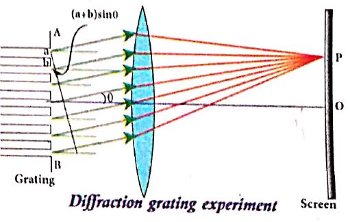
(viii) A diffraction pattern is obtained on the screen when the diffracted waves are focused on a screen using a convex lens.
(ix) Let us consider a point P at an angle θ with the perpendicular drawn from the center of the grating to the screen.
(x) The path difference ઠ between the diffracted waves from one pair of corresponding points is,
\(\delta =(a+b)sin\theta \) ........(1)
This path difference is the same for any pair of corresponding points. The point P on the screen will be maximum, when
ઠ= m λ where m = 0,1,2,3 ........(2)
Combining the above two equations, we get,
(a + b) sin θ = mλ ...............(3)
Here, m is called order of diffraction.
Condition for mth order maximum :
(i) On the side of central maxima different higher orders of diffraction maxima are formed at different angular positions. If we take,
\(N=\cfrac { 1 }{ a+b } \) .................(4)
(ii) Then, N gives the number of grating elements or rulings drawn per unit width of the grating. Normally, this number N is specified on the grating itself. Now, the equation becomes,
\(\cfrac { 1 }{ N } sin\theta =m\lambda \) (or) \(sin\theta =Nm\lambda \) ...............(5)
24.
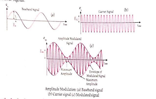
(i) If the amplitude of the carrier signal is modified according to the instantaneous amplitude of the baseband signal, then it is called amplitude modulation Here the frequency and the phase, of the carrier signal remain constant. Amplitude modulation is used in radio and TV broadcasting.
(ii) The signal shown in Figure (a) is the baseband signal that carries information. Figure(b) show the high-frequency carrier signal and Figure (c) gives amplitude modulated signal. We can see that amplitude of the carrier wave is modified in proportion to the amplitude or the baseband signal.
25.
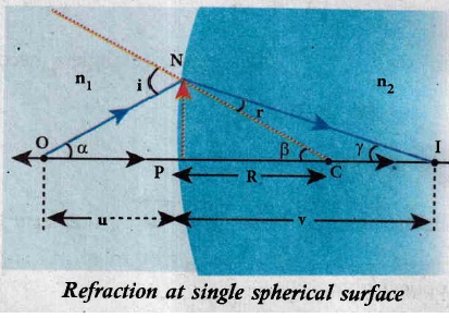
(i) Let us consider two transparent media with refractive indices n, and n, which are separated by a spherical surface. Let C be the centre of curvature of the spherical surface. Let a point object O be in the medium n.
(ii) The line OC cuts the spherical surface at the pole P of the surface. As the rays considered are paraxial rays, the perpendicular dropped for the point of incidence to the principal axis is very close to the pole (or) passes through the pole itself.
(iii) Light from O falls on the refracting surface at N. The normal drawn at the point of incidence passes through the centre of curvature C.
(iv) As n2 > n1 light in the denser medium deviates towards the normal and meets the principal axis at I where the image is formed.
(v) Snell's law in product form for the refraction at the point N can be written from the cquation,
n1 sin i = n2 sin r ...(1)
(vi) As the angles are small, sine of the angle could be approximated to the angle itself,
n1 i = n2r .........(2)
Let the angles be,
\(\angle NOP=\alpha ,\angle NCP=\beta ,\angle NIP=\gamma \)
From the right angle triangles, ∆NOP, ∆NCP and ∆NIP
\(tan\alpha =\cfrac { PN }{ PO } ;tan\beta =\cfrac { PN }{ PC } ;tan\gamma =\cfrac { PN }{ PI } \)
As these angles are small, tan of the angle could be approximated to the angle itself.
\(\alpha =\cfrac { PN }{ PO } ;\beta =\cfrac { PN }{ PC } ;\gamma =\cfrac { PN }{ PI } \) ................(3)
For the triangle, ΔONC,
\(i=\alpha +\beta \) ......(4)
For the triangle, ΔINC,
\(\beta =r+\gamma (or)r=\beta -\gamma \) ...............(5)
Substituting for i and r from equations (4) and (5) in equation (2),
\({ n }_{ 1 }(\alpha +\beta )={ n }_{ 2 }\left( { \beta -\gamma } \right) \)
After rearranging,
\({ n }_{ 1 }a+{ n }_{ 2 }\gamma =\left( { n }_{ 2 }-{ n }_{ 1 } \right) \beta \)
Substituting for α, β and y from equation
\({ n }_{ 1 }\left( \cfrac { PN }{ PO } \right) +{ n }_{ 2 }\left( \cfrac { PN }{ PI } \right) ={ (n }_{ 2 }-{ n }_{ 1 })\left( \cfrac { PN }{ PC } \right) \)
Further simplifying by cancelling PN,
\(\cfrac { { n }_{ 1 } }{ PO } +\cfrac { { n }_{ 2 } }{ PI } =\cfrac { { n }_{ 2 }-{ n }_{ 1 } }{ PC } \) .............(6)
Following sign conventions, PO = -u, PI = +v and PC = +R in equation (6)
\(\cfrac { { n }_{ 1 } }{ -u } +\cfrac { { n }_{ 2 } }{ v } =\cfrac { \left( { n }_{ 2 }-{ { n }_{ 1 } } \right) }{ R } \)
After rearranging, finally we get,
\(\cfrac { { n }_{ 1 } }{ -u } +\cfrac { { n }_{ 2 } }{ v } =\cfrac { \left( { n }_{ 2 }-{ { n }_{ 1 } } \right) }{ R } \) ..................(7)
(vii) If the first medium is air then, n1 = 1 and the second medium is taken just as n2 = n, then the equation (7) is reduced to,
\(\cfrac { n }{ v } -\cfrac { 1 }{ u } =\cfrac { \left( n-1 \right) }{ R } \) ....(8)
26.
Principle:
Cathode rays are deflected in electric and magnetic fields.
By the variation of electric and magnetic fields, mass normalized charge or the specific charge (charge per unit mass) of the cathode rays is measured.
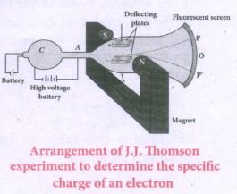
Construction and Working:
(i) Cathode rays (electron beam) produced at cathode of a highly evacuated discharge tube. Cathode rays are attracted towards anode disc A.
(ii) Pin hole in the anode disc allows only a narrow beam of cathode rays.
(iii) These cathode rays are now allowed to pass through the parallel metal plates, maintained at high voltage.
(iv) Further, discharge tube is kept in between pole pieces of magnet.
(v) Electric and magnetic fields are perpendicular to each other.
(vi) When the cathode rays strike the zinc sulphide coated screen (O), produces scintillation and hence bright spot is observed.
(i) Determination of velocity of cathode rays:
(a) For a fixed electric field between the plates, the magnetic field is adjusted such that the cathode rays (electron beam) strike at the original position O.
(b) This means that the magnitude of electric force is balanced by the magnitude of force due to magnetic field.
(ie) Ee = Bev
\(\Rightarrow v=\frac { E }{ B } \) ...(1)
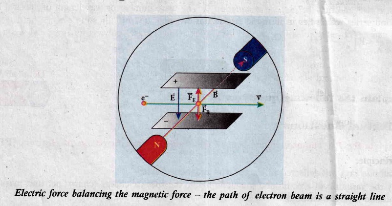
(ii) Determination of specific charge:
(a) Since accelerated from cathode to anode, the potential energy of the electron beam at the cathode is converted into kinetic energy of the electron beam at the anode.
(b) Let V be the potential difference between anode and cathode, then the potential energy is eV.
Then from law of conservation of energy,
\(eV=\frac { 1 }{ 2 } { mv }^{ 2 } \)
\(\frac { e }{ m } =\frac { { v }^{ 2 } }{ 2V } \) ....(2)
Substituting (1) in (2),
\(\frac { e }{ m } =\frac { 1 }{ 2V } \frac { { E }^{ 2 } }{ { B }^{ 2 } } \)
By substituting known values, we get
\(\frac { e }{ m } =1.7\times { 10 }^{ 11 }{ CKg }^{ -1 }\)
The specific charge \(\frac{\mathrm{e}}{\mathrm{m}}\) is independent of (a) gas used (b) nature of the electrodes
27.
(i) Galvanometer to an Ammeter:
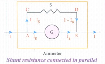
(i) Ammeter is an instrument used to measure current flowing in the electrical circuit.
(ii) The Ammeter must offer low resistance such that it will not change the current passing through it. So, ammeter is connected in series to measure the circuit current.
(iii) A galvanometer is converted into an ammeter by connecting a low resistance in parallel with the galvanometer.
(iv) Let I be the current passing through the circuit. When current I reaches the junction A, it divides into two components.
a) Ig → Current passing through the galvanometer
b) I - Ig → Current passing through the shunt resistance.
(v) The potential difference across the galvanometer is same as the potential difference across the shunt resistance.
\(\mathrm{V}_{\text {galvanometer }} =\mathrm{V}_{\text {shunt }} \)
\(\Rightarrow \mathrm{I}_{\mathrm{g}} \mathrm{R}_{\mathrm{g}} =\left(\mathrm{I}-\mathrm{I}_{g}\right) \mathrm{S} \)
\(\mathrm{S} =\frac{I_{g}}{\left(I-I_{g}\right)} R_{g} \) (or)
\(\mathrm{I}_{\mathrm{g}}=\frac{S}{S+R_{g}} I \Rightarrow I_{g} \propto I\)
Since, the deflection in the galvanometer is proportional to the current passing through it.
\(\theta=\frac{1}{G} I_{g} \Rightarrow \theta \propto I_{g} \Rightarrow \theta \propto I\)
Where, Rg → Galvanometer resistance, S → Shunt resistance.
Since shunt resistance is connected in parallel to galvanometer,
Effective resistance,\(\frac{1}{R_{e f f}}=\frac{1}{R_{g}}+\frac{1}{S} \Rightarrow R_{e f f}=\frac{R_{g} S}{R_{g}+S}=R_{a}\)
Ra ⇒ low resistance. An ideal ammeter has zero resistance.
The percentage error in measuring a current through an ammeter is,
\(\frac{\Delta I}{I} \times 100 \%=\frac{I_{i d e a l}-I_{a c t u a l}}{I_{a c t u a l}} \times 100 \%\)
(ii) Galvanometer to a voltmeter:
i) A voltmeter is an instrument used to measure potential difference across any two points in the electrical circuits.
ii) Voltmeter must have high resistance and when it is connected in parallel, it will rot draw appreciable current so that it will indicate the true potential difference.
iii) A galvanometer is converted into a voltmeter by connecting high resistance Rh in series with galvanometer.
iv) Let Rg be the resistance of galvanometer and Ig be the current with which the galvanometer produces full scale deflection.
v) Since the galvanometer is connected in series with high resistance, the current in the electrical circuit is same as the current passing through the galvanometer.
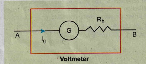
\(\mathrm{I}=\mathrm{I}_{\mathrm{g}} \)
\(\mathrm{I}=I_{g} \Rightarrow I_{g}=\frac{\text { potential difference }}{\text { total resistance }} \)
Since the galvanometer and high resistance are connected in series, the voltmeter resistance is,
\(R_{v} =R_{g}+R_{h} \)
Therefore,
\(I_{g} =\frac{V}{R_{g}+R_{h}} \)
\(\Rightarrow R_{h} =\frac{V}{I_{g}}-R_{g} \)
Note that \(I_{g} \propto V\)
Rh is very large. An ideal voltmeter has infinite resistance
28.
Principle:
The principle of transformer is the mutual induction between two coils. That is, when an electric current passing through a coil changes with time, an emf is induced in the neighbouring coil.
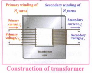
Construction:
(i) In the simple construction of transformers, there are two coils of high mutual inductance wound over the same transformer core.
(ii) The core is generally laminated and is made up of a good magnetic material like silicon steel. Coils are electrically insulated but magnetically linked via transformer core.
(iii) The coil across which alternating voltage is applied is called primary coil P and the coil from which output power is drawn out is called secondary coil S. The assembled core and coils are kept in a container which is filled with suitable medium for better insulation and cooling purpose.
Working:
(i) If the primary coil is connected to a source of alternating voltage, an alternating magnetic flux is set up in the laminated core.
(ii) If there is no magnetic flux leakage, then whole of magnetic flux linked with primary coil is also linked with secondary coil.
(iii) This means that rate at which magnetic flux changes through each turn is same for both primary and secondary coils.
(iv) As a result of flux change, emf is induced in both primary and secondary coils. The emf induced in the primary coil vp or back of εp is given by,
vp = εp = -Np \(\frac{dФ_B}{dt}\) ........(1)
(vi) The frequency of alternating magnetic flux in the core is same as the frequency of the applied voltage. Therefore, induced emf in secondary will also have same frequency as that of applied voltage. The emf induced in the secondary coil εs is given by ,
εs = -Ns\(\frac{dФ_B}{dt}\)
Where Np and Ns are the number of turns in the primary and secondary coil respectively. If the secondary circuit is open, then εs = ሀs where u is the voltage ሀs across secondary coil
ሀs = εs = -Ns \(\frac{dФ_B}{dt}\) ........(2)
From equations (1) and (2),
\(\frac{v_s}{v_p}=\frac{N_s}{N_p}\) = K ........(3)
(vii) This constant K is known as voltage transformation ratio. For an ideal transformer, input power vpip= Output power vsis
where ip and is are the currents in the primary and secondary coil respectively.
(ix) Therefore,
\(\frac{V_s}{V_p}=\frac{N_s}{N_p}=\frac{I_p}{I_s}\) ........(4)
Equation (4) is written in terms of amplitude of corresponding quantities
\(\frac{V_s}{V_p}=\frac{N_s}{N_p}=\frac{I_p}{I_s}\) = K
i) If Ns> Np (or K > 1), ∴ Vs > Vp and Is < Ip This is the case of step-up transformer in which voltage is increased and the corresponding current is decreased.
ii) If Ns< Np (or K < 1), ∴ Vs < Vp and Is > Ip This is step-down transformer where voltage is decreased and the current is increased.
Efficiency of a transformer:
The efficiency η of a transformer is defined as the ratio of the useful output power to the input power. Thus,
\(η=\frac{Outpur \ power}{Input \ power}\times100% \) % ....(5)
29.
Case (i): Electric field due to an electric dipole at points on the axial Iine:
Consider an electric dipole placed on the x-axis as shown in Figure. A point C is located at a distance of r from the midpoint O (of the dipole) along the axial line.
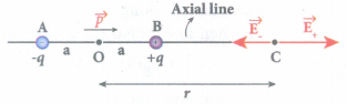
The electric field at a point C due to +q is
\({ \vec { E } }_{ + }=\frac { 1 }{ 4\pi { \varepsilon }_{ 0 } } \frac { q }{ { (r-a) }^{ 2 } } \) along BC
Since the electric dipole moment vector \(\vec { p } \) is from -q to +q and is directed along BC, the above equation is rewritten as
\({ \vec { E } }_{ + }=\frac { 1 }{ 4\pi { \varepsilon }_{ 0 } } \frac { q }{ { (r-a) }^{ 2 } } \hat { p } \) ....(1)
When \(\vec { p } \) is the electric dipole moment unit vector from -q to +q. The electric field at a point C due to -q is
\({ \vec { E } }_{ - }=-\frac { 1 }{ 4\pi { \varepsilon }_{ 0 } } \frac { q }{ { (r+a) }^{ 2 } } \hat { p } \) ....(2)
Since +q is located closer to the point C than -q, \({ \vec { E } }_{ + }\) is stronger than \({ \vec { E } }_{ - }\). Therefore, the length of the \({ \vec { E } }_{ + }\) vector is drawn larger than that of \({ \vec { E } }_{ - }\) vector.
The total electric field at point C is calculated using the superposition principle of the electric field.
\({ \vec { E } }_{ tot }={ \vec { E } }_{ + }+{ \vec { E } }_{ - }\)
\(=\frac { 1 }{ 4\pi { \varepsilon }_{ 0 } } \frac { q }{ { (r-a) }^{ 2 } } \hat { p } -\frac { 1 }{ 4\pi { \varepsilon }_{ 0 } } \frac { q }{ { (r+a) }^{ 2 } } \hat { p } \)
\({ \vec { E } }_{ tot }=\frac { q }{ 4\pi { \varepsilon }_{ 0 } } \left( \frac { 1 }{ { (r-a) }^{ 2 } } -\frac { 1 }{ { (r+a) }^{ 2 } } \right) \hat { p } \) ....(3)
\({ \vec { E } }_{ tot }=\frac { 1 }{ 4\pi { \varepsilon }_{ 0 } } q\left( \frac { 4ra }{( { r }^{ 2 }-{ a }^{ 2 })^2 } \right) \hat { p } \) ...(4)
Note that the total electric field is along \({ \vec { E } }_{ + }\), since +q is closer to C than -q.
If the point C is very far away from the dipole then (r >> a). Under this limit the term \(({ r }^{ 2 }-{ a }^{ 2 })\approx { r }^{ 2 }\).
Substituting this into equation (4), we get
\({ \vec { E } }_{ tot }=\frac { 1 }{ 4\pi { \varepsilon }_{ 0 } } \left( \frac { 4aq }{ { r }^{ 3 } } \right) \hat { p } (r>>a)\)
\(since\quad 2aq\hat { p } =\vec { p } \)
\({ \vec { E } }_{ tot }=\frac { 1 }{ 4\pi { \varepsilon }_{ 0 } } \frac { 2\vec { p } }{ { r }^{ 3 } } (r>>a)\) ...(5)
The direction \({ \vec { E } }_{ tot }\) is shown in Figure.
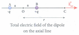
NOTE: If the point C is chosen on the left side of the dipole, the total electric field is still in the direction of \(\vec { p } \).
Case (ii) Electic field due to an electric dipole at a point on the equatorial plane:
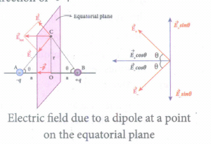
Consider a point C at a distance r from the midpoint O of the dipole on the equatorial plane. Since the point C is equidistant from +q and -q, the magnitude of the electric fields of +q and -q are the same. The direction of \({ \vec { E } }_{ + }\) is along BC and the direction of \({ \vec { E } }_{ - }\) is along CA. \({ \vec { E } }_{ + }\) and \({ \vec { E } }_{ - }\) are resolved into two components; one component parallel to the dipole axis and the other perpendicular to it. The perpendicular components \(|{ \vec { E } }_{ + }|\) sinθ and \(|{ \vec { E } }_{ -}|\) sinθ are equal in magnitude and oppositely directed and cancel each other. The magnitude of the total electric field at point C is the sum of the parallel components of \({ \vec { E } }_{ + }\) and \({ \vec { E } }_{ - }\) and its direction is along \(-\hat{p}\) as shown in the Figure.
\({ \vec { E } }_{ tot }=-|{ \vec { E } }_{ + }|cos\theta \hat { p } -|{ \vec { E } }_{ - }|cos\theta \hat { p } \) ...(6)
The magnitudes \({ \vec { E } }_{ + }\) and \({ \vec { E } }_{ - }\) are the same and given by,
\(|{ \vec { E } }_{ + }|=|{ \vec { E } }_{ - }|=\frac { 1 }{ 4\pi { \varepsilon }_{ 0 } } \frac { q }{ (r^2+a^2) } \) ...(7)
By substituting equation (7) into equation (6), we get
\({ \vec { E } }_{ tot }=\frac { 1 }{ 4\pi { \varepsilon }_{ 0 } } \frac { 2qcos\theta }{ ({ r }^{ 2 }+{ a }^{ 2 }) } \hat { p } ....(8)\)
\(=-\frac { 1 }{ 4\pi { \varepsilon }_{ 0 } } \frac { 2qa }{ ({ r }^{ 2 }+{ a }^{ 2 })^{ \frac { 3 }{ 2 } } } \hat { p } \)
Since \(cos \theta =\frac { a }{ \sqrt { { r }^{ 2 }+{ a }^{ 2 } } } \)
\({ \vec { E } }_{ tot }=\frac { 1 }{ 4\pi { \varepsilon }_{ 0 } } \frac { \vec { p } }{ ({ r }^{ 2 }+{ a }^{ 2 })^{ \frac { 3 }{ 2 } } } \)
Since \(\vec { p } \) = 2qa\(\hat { p } \) ...(9)
At very large distances (r >> a), the equation (9) becomes
\({ \vec { E } }_{ tot }=\frac { 1 }{ 4\pi { \varepsilon }_{ 0 } } \frac { \vec { p } }{ { r }^{ 3 } } (r>>a)\) ...(10)
Negative sign shows that direction of Electric field is opposite to the direction of dipole moment vector.
30.
(i) The meter bridge is another form of Wheatstone's bridge. It consists of a uniform manganin wire AB of one meter length.
(ii) This wire is stretched along a meter scale on a wooden board between two copper strips C and D. Between these two copper strips another copper strip E is mounted to enclose two gaps G1 and G2.
(iii) An unknown resistance P is connected in G1 and a standard resistance Q is connected in G2. A jockey (conducting wire) is connected to the terminal E on the central copper strip through a galvanometer (G) and a high resistance (HR).
(iv) The exact position of jockey on the wire can be read on the scale. A Lechlanche cell and a key (K) are connected across the ends of the bridge wire.

(v) The position of the jockey on the wire is adjusted so that the galvanometer shows zero deflection. Let the position of jockey at the wire be at J.
(vi) The resistances corresponding to AJ and JB of the bridge wire now form the resistance R and S of the Wheatstone's bridge. Then for the bridge balance.
\(\cfrac { P }{ Q } =\cfrac { R }{ S } =\cfrac { { r }.AJ }{ { r }.JB } \)
where r' is the resistance per unit length of wire
\(\cfrac { P }{ Q } =\cfrac { AJ }{ JB } =\cfrac { { l }_{ 1 } }{ { l }_{ 2 } } \)
\(P=Q\cfrac { { l }_{ 1 } }{ { l }_{ 2 } } \)
(vii) By interchanging P and Q, another set of readings are taken and the average value of P is value of unknown resistance.

12th Standard Syllabus & Materials
12th Standard
TN 12th Computer Applications களப்பெயர் முறைமை (DNS) Sample Question Papers Study Material - QB365 Set A
NEW12th Standard
TN 12th Computer Applications வலையமைப்பு எடுத்துக்காட்டுகள் மற்றும் நெறிமுறைகள் Sample Question Papers Study Material - QB365 Set A
NEW12th Standard
TN 12th Computer Applications கணினி வலையமைப்பு ஓர் அறிமுகம் Sample Question Papers Study Material - QB365 Set A
NEW12th Standard
TN 12th Computer Applications PHP-உடன் MySQL-ஐ இணைத்தல் Sample Question Papers Study Material - QB365 Set A



Tamilnadu Stateboard 12th Standard Subjects

Maths

Chemistry
Physics

Biology

Computer Science

Business Maths and Statistics

Economics

Commerce

Accountancy

History

Computer Applications
Biology
Computer Technology
Computer Applications
Computer Science
Business Maths and Statistics
Commerce
Economics
Maths
Chemistry
Physics
Computer Technology
History
Accountancy

Tamil

English

French
Tamilnadu Stateboard Standards


