
 100% FREE ACCESS
12th Standard Syllabus & Materials
12th Standard
TN 12th Maths Applications of Matrices and Determinants Sample Question Papers Study Material - QB365 Set A
NEW12th Standard
TN 12th Computer Applications மின்னணு தரவு பரிமாற்றம் Sample Question Papers Study Material - QB365 Set A
NEW12th Standard
TN 12th Computer Applications மின் - வணிக பாதுகாப்பு அமைப்புகள் Sample Question Papers Study Material - QB365 Set A
NEW12th Standard
TN 12th Computer Applications மின்னணு செலுத்தல் முறைகள் Sample Question Papers Study Material - QB365 Set A
NEW12th Standard
TN 12th Computer Applications மின் - வணிகம் Sample Question Papers Study Material - QB365 Set A
NEW12th Standard
TN 12th Computer Applications திறந்த மூல கருத்துருக்கள் Sample Question Papers Study Material - QB365 Set A

Published on: 28/11/2025
Download Tamil Nadu 12th Standard Physics question papers, model tests, one-mark questions, important questions, and public exam papers in PDF format. Free study materials and answer keys for TN State Board students.
Questions + Answers key
Take MCQ Physics Test
1.
Which of the following graphs correctly represents the variation of particle momentum with associated de Broglie wavelength?
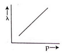
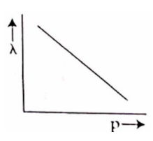
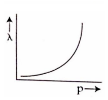

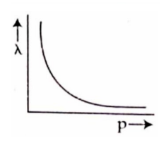
2.
In a concave mirror experiment, an object is placed at a distance x, from, the focus and the image is formed at a distance x2 from the focus. The focal length of the mirror would be ______________.
xI x2
\(\sqrt { { x }_{ 1 }{ x }_{ 2 } } \)
\(\cfrac { { x }_{ 1 }+{ x }_{ 2 } }{ 2 } \)
\(\sqrt { \cfrac { { x }_{ 1 } }{ { x }_{ 2 } } } \)
3.
Equation of length contraction is ________
l-l0 =\(\sqrt { 1-\frac { { v }^{ 2 } }{ { c }^{ 2 } } } \)
\(\frac { l }{ { l }_{ 0 } } \sqrt { 1-\frac { { v }^{ 2 } }{ { c }^{ 2 } } } \)
l0=\(\sqrt { 1-\frac { { v }^{ 2 } }{ { c }^{ 2 } } } \)
\(\frac { { v }^{ 2 } }{ { c }^{ 2 } } \)=(l-l0)2+1
4.
The ratio between the base-emitter voltage to the corresponding change in base current is _________
input impedance
output impedance
total impedance
total current
5.
The echo signal of a RADAR is demodulated by a _________.
decoder
transmitter
superhet receiver
rectifier
6.
The alloys used for muscle wires in Robots are _____.
Shape memory alloys
Gold copper alloys
Gold silver alloys
Two dimensional alloys
7.
The barrier potential of a silicon diode is approximately, ______.
0.7 V
0.3 V
2.0 V
2.2 V
8.
The half-life period of a radioactive element A is same as the mean life time of another radioactive element B. Initially both have the same number of atoms. Then _____.
A and B have the same decay rate initially
A and B decay at the same rate always
B will decay at faster rate than A
A will decay at faster rate than B
9.
10.
Emission of electrons by the absorption of heat energy is called ______ emission.
photoelectric
field
thermionic
secondary
11.
12.
One of the of Young’s double slits is covered with a glass plate as shown in figure. The position of central maximum will,_____.
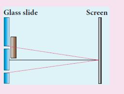
get shifted downwards
get shifted upwards
will remain the same
data insufficient to conclude
13.
Two point white dots are 1 mm apart on a black paper. They are viewed by eye of pupil diameter 3 mm approximately. The maximum distance at which these dots can be resolved by the eye is_____. [take wavelength of light, λ = 500 nm]
1 m
5 m
3 m
6 m
14.
If the velocity and wavelength of light in air is Va and λa and that in water is Vw and λw, then the refractive index of water is______.
\(\frac{V_W}{V_a}\)
\(\frac{V_a}{V_W}\)
\(\frac{\lambda_W}{\lambda_a}\)
\(\frac{{V_a}\lambda_a}{{V_W}\lambda_W}\)
15.
The speed of light in an isotropic medium depends on, ______.
its intensity
its wavelength
the nature of propagation
the motion of the source w.r.t medium
16.
What do you mean by skip distance?
17.
Calculate the cut-off wavelength and cutoff frequency of x-rays from an x-ray tube of accelerating potential 20,000 V.
18.
State de Broglie hypothesis.
19.
What is photoelectric effect?
20.
Mention any two advantages and disadvantages of Robotics.
21.
22.
Define impact parameter.
23.
State Huygens’ principle.
24.
Why do stars twinkle?
25.
List out the advantages and limitations of frequency modulation.
26.
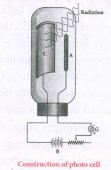
Give the applications photocell.
27.
Why is yellow light preferred to during fog?
28.
Derive an expression for de Broglie wavelength of electrons.
29.
30.
Explain the idea of carbon dating.
31.
State and obtain Malus’ law. (or) State Malus' Law.
32.
What is Fresnel’s distance? Obtain the equation for Fresnel’s distance.
33.
Derive the relation between f and R for a spherical mirror.
34.
Describe briefly Davisson – Germer experiment which demonstrated the wave nature of electrons.
35.
36.
Draw the circuit diagram of a half-wave rectifier and explain its working.
37.
Explain the Young’s double slit experimental setup and obtain the equation for path difference.
38.
Obtain lens maker’s formula and mention its significance.
39.
Obtain the law of radioactivity.
40.
Explain the ampitude modulation with necessary diagrams.
41.
Discuss the spectral series of hydrogen atom.
42.
Derive the mirror equation and the equation for lateral magnification.
43.
Explain the J.J. Thomson experiment to determine the specific charge of electron.
1.
(d)
2.
(b)
\(\sqrt { { x }_{ 1 }{ x }_{ 2 } } \)
3.
(b)
\(\frac { l }{ { l }_{ 0 } } \sqrt { 1-\frac { { v }^{ 2 } }{ { c }^{ 2 } } } \)
4.
(a)
input impedance
5.
(c)
superhet receiver
6.
They are thin strands of wire made of shape memory alloys. They can contract by 5% when electric current is passed through them.
7.
(a)
0.7 V
8.
TA1/2 = ፒB
\(\frac{0.6931}{\lambda_{\mathrm{A}}}=\frac{1}{\lambda_{\mathrm{B}}} \)
\(\lambda_{\mathrm{B}}=\frac{\lambda_{\mathrm{A}}}{0.6931}=1.44 \lambda_{\mathrm{A}}\)
Hence, B will decay at faster rate than A
9.
(b)
10.
(c)
thermionic
11.
(b)
12.
(b)
get shifted upwards
13.
λ = 500 nm = 500 x 10-9 m
x = 3 mm = 3 x 10⁻³ m
a = 1 mm = 1 x 10⁻³ m
\(d=\frac{xa}{1.22 \lambda}\)
\(d=\frac{3 \times1\times10^{-6}}{1.22 \times500\times10^{-9}}\)
\(=\frac{3 \times1\times10^{-6}}{6.10 \times 10^{-7}}\)
\(d=\frac{30}{6.1}=5 m\)
14.
Refractive index of water \(=\frac{Velocity \ of \ light \ in \ air(V_s)}{Velocity \ of \ light \ in \ water(V_w)}\)
15.
v = nג
In an isotropic medium, there is no change in the frequency of the light. So, the speed of light depends on wavelength of light.
16.
The shortest distance between the transmitter and the point of reception of the sky wave along the surface is called as the skip distance.
17.
The cut-off wavelength of the characteristic x - rays is
\({ \lambda }_{ ° }\frac { 12400 }{ V } \mathring { A } =\frac { 12400 }{ 20000 } \mathring { A }\)
= 0.62 \(\mathring { A } \)
The corresponding frequency is
\({ \upsilon }_{ o }=\frac { c }{ { \lambda }_{ o } } =\frac { 3\times 10^{ 8 } }{ 0.62\times 10^{ -10 } }\) = 4.84 x 10¹⁸ Hz
18.
According to de Broglie hypothesis, if radiation has a dual nature, then the moving particles of matter Iike electrons, protons, neutrons in motion should exhibit wave like character under an appropriate conditions. These waves are called de Broglie waves or matter waves.
19.
The ejection of electrons from the metal plate when illuminated by light or any electromagnetic radiation of suitable wavelength (or frequency) is called photoelectric effect.
20.
Advantages of Robotics:
(i) Robots are more precise and error free in performing the task.
(ii) Robots never get tired like humans. It can work for 24 x 7. Hence absenteeism in work place can be reduced.
Disadvantages of Robotics:
(i) Unemployment problem will increase.
(ii) Robots can perform defined tasks and cannot handle unexpected situations.
21.
22.
The impact parameter is defined as the perpendicular distance between the centre of the gold nucleus and the direction of velocity vector of alpha particle when it is at a large distance in the Rutherford's alpha particles scattering experiment.
23.
According to Huygens's principle, each point of the wavefront is the source of secondary wavelets emanating from these points spreading out in all directions with the speed of the wave. These are called as secondary wavelets.
24.
Stars appear twinkling because of the movement of the atmospheric layer with varying refractive indices due to refraction.
25.
Advantages of FM:
i) In FM, there is a large decrease in noise. This leads to an increase in signal-noise ratio.
ii) The operating range is quite large.
iii) The transmission efficiency is very high as all the transmitted power is useful
iv) FM Bandwidth covers the entire frequency range which humans can hear. Due to this, FM radio has better quality compared to AM radio.
Limitations of FM:
i) FM requires a much wider channel.
ii) FM transmitters and receivers are more complex and costly.
iii) In FM reception, less area is covered compared to AM.
26.
(i) Photo cells are used as switches and sensors.
(ii) Automatic switch on and off of street lights.
(iii) They are used for reproduction of sound in motion pictures
(iv) They are used as timers to measure the speed of athletes during a race.
(v) In photography, they are used to measure the intensity of the given light and to calculate the exact time of exposure.
27.
Yellow light is preferred to during fog because of penetrates deeply due to its longer wave length it is much smaller than fog particles (The scattering effect of fog is independent of wave length).
28.
(i) An electron of mass m is accelerated through a potential difference of V volt. The kinetic energy acquired by the electron is given by
\(\cfrac { 1 }{ 2 } { mv }^{ 2 }=ev\)
(ii) Therefore, the speed v of the electron is
\(v=\sqrt { \cfrac { 2ev }{ m } } \)
Hence, the de Broglie wavelength of the matter waves associated with electron is
\(\lambda =\cfrac { h }{ mv } =\cfrac { h }{ \sqrt { 2mev } } \)
(iii) Substituting the known values in the above equation, we get
\(\lambda =\cfrac { 6.26\times { 10 }^{ -34 } }{ \sqrt { 2V\times 1.6\times { 10 }^{ -19 }\times 9.11\times { 10 }^{ -31 } } } \)
= \(\cfrac { 12.27\times { 10 }^{ -10 } }{ \sqrt { V } } m\)
\(\lambda =\cfrac { 12.27 }{ \sqrt { V } } \overset { o }{ A } \)
(iv) Since the kinetic energy of the electron, K = eV, then the de Broglie wavelength associated with electron can be also written as
\(\lambda =\cfrac { h }{ \sqrt { 2mK } } \)
29.
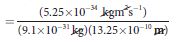
30.
(i) The application of beta decay is radioactive dating or carbon dating.
(ii) Using this technique, the age of an ancient object can be calculated.
(iii) All living organisms absorb carbon dioxide (CO2) from air to synthesize organic molecules.
(iv) In this absorbed CO2, the major part is \(_{ 6 }^{ 12 }{ C }\) and very small fraction (1.3 x 10⁻¹²) is radioactive \(_{ 6 }^{ 14 }{ C }\)whose half-life is 5730 years
(v) Carbon-14 in the atmosphere is always decaying but at the same time, cosmic rays from outer space are continuously bombarding the atoms in the atmosphere which produces \(_{ 6 }^{ 14 }{ C }\)
(v) So the Continuous production and decay of \(_{ 6 }^{ 14 }{ C }\) in the atmosphere keep the ratio of \(_{ 6 }^{ 14 }{ C }\) always constant.
(vi) Since our human body, tree or any living organism continuously absorbs CO2 from the atmosphere, the ratio of \(_{ 6 }^{ 14 }{ C }\) to \(_{ 6 }^{ 12 }{ C }\) in the living organism is also nearly constant.
(vii) But when the organism get dies, it stops absorbing CO2
(viii) Now \(_{ 6 }^{ 14 }{ C }\) starts to decay, the ratio of \(_{ 6 }^{ 14 }{ C }\) to \(_{ 6 }^{ 12 }{ C }\) in a dead organism or specimen decreases over the years.
(ix) Suppose the ratio of \(_{ 6 }^{ 14 }{ C }\) to \(_{ 6 }^{ 12 }{ C }\) in the ancient tree pieces excavated is known, then the age of the tree pieces can be calculated.
31.
When a beam of plane polarised light of intensity (Io) is incident on an analyser, the intensity of light (I) transmitted from the analyser varies directly as the square of the cosine of angle between the transmission axes of polariser and analyser.
\(I={ I }_{ o }cos^{ 2 }\theta \)
Consider the plane of polariser and analyser are inclined to each other at an angle ፀ. Let Io be the intensity and 'a' be the amplitude of the electric vector transmitted by the polariser. The amplitude 'a' of the incident light has two rectangular components, (acosθ) and (asinθ) which are the parallel and perpendicular components to the axis of transmission of the analyser. Only the component (acosθ) will be transmitted by the analyzer.
According to Malus's law
\(I\propto \left( acos\theta \right) ^{ 2 }\)
\(I=k\left( acos\theta \right) ^{ 2 }\)
Where k is constant of proportionality,
I = ka2 cos2 θ
I = Io = cos2 θ
Where Io = ka2 is the maximum intensity of light transmitted from the analyser.
32.
Fresnel's distance is the distance upto which the ray optics is valid in terms of rectilinear propagation of light.
(or)
Fresnel's distance is the distance upto which ray optics is obeyed and beyond which ray optics is not obeyed but, wave optics becomes significant,
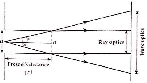
The diffraction equation for first minimum is, sinθ \(=\frac{ \lambda}{2};\)
When θ is small, θ \(=\frac{ \lambda}{2}\)
From the definition of Fresnel's distance, 2θ\(=\frac{a}{z}\) (or) θ \(=\frac{a}{2z}\)
Equating the above two equation for θ gives, \(\frac{\lambda}{a}=\frac{a}{2z}\)
After rearranging, we get Fresnel's distance z as,
\(z=\cfrac { { a }^{ 2 } }{ 2\lambda } \)
33.
Relation between f and R:
C ⇒ Center of curvature
F ⇒ Principal focus
i ⇒ Angle of incidence
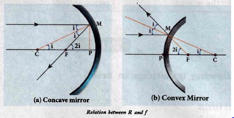
The angles
\(\tan i=\frac{P M}{P C} \text { and } \tan 2 i=\frac{P M}{P F}\)
As the angles are small, tan i = i and tan 2i = 2i.
\(\mathrm{i}=\frac{\mathrm{PM}}{\mathrm{PC}} \text { and } 2 \mathrm{i}=\frac{\mathrm{PM}}{\mathrm{PF}}\)
Simplifying further,
\(2 \frac{\mathrm{PM}}{\mathrm{PC}}=\frac{\mathrm{PM}}{\mathrm{PF}} ; 2 \mathrm{PF}=\mathrm{PC}, \mathrm{R}=2 \mathrm{f}\)
PF is focal length f and PC is the radius of curvature R.
R = 2f (or) f = R/2
34.
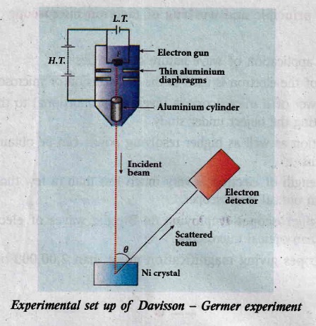
Davisson - Germer experiment
(i) The filament F is heated by a low tension (L . T) battery. Electrons are emitted from the hot filament by thermionic emission.
(ii) They are then accelerated due to the potential diference between the filament and the anode aluminum cylinder by a high tension (H.T) battery.
(iii) Electron beam is collimated by using two thin aluminum diaphragms and is allowed to strike a single crystal of Nickel.
(iv) The electrons scattered by Niatoms in diflerent directions are received by the electron detector which measures the intensity of scattered electron beam.
(v) The detector is capable of rotation in the plane of the paper, so that the angle (\(\theta\)) between the incident beam and the scattered beam can be changed at our will.
(vi) The intensity of the scattered electron beam is measured as a function of the angle \(\theta\).
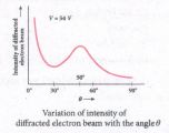
(i) Figure shows the variation of intensity of the scattered electrons with the angle \(\theta\) for the accelerating voltage of 54 V.
(ii) For a given accelerating voltage V, the scattered wave shows a peak or maximum at an angle of 50o to the incident electron beam.
(iii) This peak in intensity is attributed to the constructive interference of electrons diffracted from various atomic layers of the target material.
(iv) From the known value of interplanar spacing of Nickel, the wavelength of the electron wave has been experimentally calculated as 1.65\(\overset { o }{ A }\).
(v) The wavelength can also be calculated from de Broglie relation for V = 54 V from equation as
\(\lambda =\cfrac { 12.27 }{ \sqrt { V } } \overset { o }{ A } =\cfrac { 12.27 }{ \sqrt { 54 } } \)
\(\lambda =1.67\overset { o }{ A } \)
(vi) This value agrees very well with the experimentally observed wavelength of 1.65 \(\overset { o }{ A }\). Thus this experiment directly verifies de Broglie's hypothesis of the wave nature of moving particles.
35.
36.
HaIf wave rectifier:
Only one half of the input wave reaches the output. Therefore it is called half wave rectifier.
Construction:
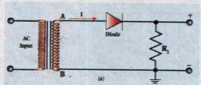
(i) The circuit consists of a transformer, a p-n junction diode and a resistor
(ii) In a half wave rectifier circuit, either a positive half or the negative half of the AC input is passed through by the diode while the other half is blocked
(iii) It acts as a rectifier diode.
.jpg)
(iv) Efficiency (η) is the ratio of the output DC power to the AC input power circuit. supplied to the circuit.
(v) The efficiency (η) of a half wave rectifier is found to be 40.6 %.
.jpg)
37.
Experimental setup:
(i) S is a source s1 and s2 the double slits which are at equidistances from 's'. Wavefronts from s1 and s2 spread out and overlap on other side of double slit.
(ii) When a screen is placed at a distance of about 1 meter from the slits, alternate bright and dark fringes which are equally spaced appear on the screen. These are called interference fringes or bands.
(iii) Using an eyepiece the fringes can be seen directly. At the center point O on the screen, waves from s1 and s2 travel equal distances and arrive in-phase as shown in Figure.
(iv) These two waves constructively interfere and bright fringe is observed at O. This is called cental bright fringe.
(v) When one of the slits is closed, The fringes disappear and there in uniform illumination on the screen.
(vi) This shows clearly that the bands are due to interference.
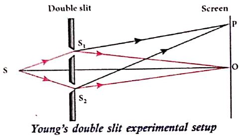
Equation for path difference :
(i) The Let d be the distance between the double slits s1 and s2 which act as coherent sources of wavelength λ.
(ii) A screen is placed parallel to the double slit at a distance D from it.
(iii) P is any point at a distance y from O.
(iv) The waves from S1 and S2 meet at P either in-phase or out-of-phase depending upon the path difference between the two waves.
.JPG)
The path difference \(\delta\) between the light waves from s1 and s2 to the point p is,
\(\delta=\mathrm{S}_{2} \mathrm{P}-\mathrm{S}_{1} \mathrm{P}\)
\(\delta=\mathrm{S}_{2} \mathrm{P}-\mathrm{MP}=\mathrm{S}_{2} \mathrm{M}\) .........(1)
\(\angle \mathrm{OCP}=\angle \mathrm{S}_{2} \mathrm{~S}_{1} \mathrm{M}=\theta\)
In right angle triangle \(\Delta \mathrm{S}_{1} \mathrm{S}_{2} \mathrm{M}\), the path difference S2M = d sin \(\theta\)
\(\delta=d \sin \theta\) ...........(2)
If the angle \(\theta\) is small, \(\sin \theta \approx \tan \theta \approx \theta\)
From the right angle triangle \(\Delta \mathrm{OCP}, \tan \theta=\frac{\mathrm{y}}{\mathrm{D}}\)
The path differences \(\delta=\frac{d y}{D}\) ...........(3)
Based on the condition of the path difference, the point P may have a bright (or) dark fringe
38.
(i) Let us consider a thin lens made up of a medium of refractive index n2 is placed in a medium of refractive index n1. Let R1 and R2 be the radii of curvature of two spherical surfaces (1) and (2) respectively and P be the pole.
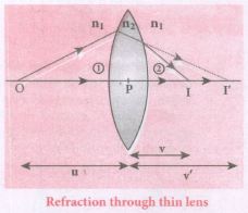
(ii) Consider a point object 'O' on the principal axis. A paraxial ray from 'O' which falls very close to P, after refraction at the surface (1) forms image at 1'.
(iii) Before it does so, it is again refracted by the surface (2). Therefore the final image is formed at I.
(iv) The general equation for the refraction at a single spherical surface is given from Equation,
\(\cfrac { { n }_{ 2 } }{ v } -\cfrac { { n }_{ 1 } }{ v} =\cfrac { \left( { n }_{ 2 }-{ n }_{ 1 } \right) }{ { R } } \)
For the refracting surface (1), the light goes from n1 to n2
\(\cfrac { { n }_{ 2 } }{ v' } -\cfrac { { n }_{ 1 } }{ u } =\cfrac { \left( { n }_{ 2 }-{ n }_{ 1 } \right) }{ { R }_{ 1 } } \) .....(1)
For the refracting surface (2), the light goes from n2 to n1
\(\frac{n_{1}}{v}+\frac{n_{2}}{v^{\prime}}=\frac{\left(n_{1}-n_{2}\right)}{R_{2}}\) ......(2)
For surface (2) I' acts as virtual object.
Adding the above two equations (1) and (2)
\(\cfrac { { n }_{ 1 } }{ v } -\cfrac { { n }_{ 1 } }{ u } =\left( { n }_{ 2 }-{ n }_{ 1 } \right) \left( \cfrac { 1 }{ { R }_{ 1 } } -\cfrac { 1 }{ { R }_{ 2 } } \right) \)
on further simplifying and rearranging,
\(\cfrac { 1 }{ v } -\cfrac { 1 }{ u } =\left( \cfrac { { n }_{ 2 }-{ n }_{ 1 } }{ { n }_{ 1 } } \right) \left( \cfrac { 1 }{ { R }_{ 1 } } -\cfrac { 1 }{ { R }_{ 2 } } \right) \)
\(\cfrac { 1 }{ v } -\cfrac { 1 }{ u } =\left( \cfrac { { n }_{ 2 } }{ n_{ 1 } } -1 \right) \left( \cfrac { 1 }{ { R }_{ 1 } } -\cfrac { 1 }{ { R }_{ 2 } } \right) \) ....(3)
If the object is at infinity, the image is formed at the focus of the lens. Thus, for u = \(\infty\), v = f. Then the equation becomes.
\(\cfrac { 1 }{ f } -\cfrac { 1 }{ \infty } =\left( \cfrac { { n }_{ 2 } }{ { { n }_{ 1 } } } -1 \right) \left( \cfrac { 1 }{ { R }_{ 1 } } -\cfrac { 1 }{ { R }_{ 2 } } \right) \)
\(\cfrac { 1 }{ f } =\left( \cfrac { { n }_{ 2 } }{ { n }_{ 1 } } -1 \right) \left( \cfrac { 1 }{ { R }_{ 1 } } -\cfrac { 1 }{ { R }_{ 2 } } \right) \) ......(4)
If the lens is kept in air, then we can take n2 = n and n1 = 1. So the equation (4) becomes,
\(\\ \cfrac { 1 }{ f } =\left( n-1 \right) \left( \cfrac { 1 }{ { R }_{ 1 } } -\cfrac { 1 }{ { R }_{ 2 } } \right) \) ..(5)
The above equation is called the lens maker's formula.
Significance:
It tells the lens manufacturers what curvature is needed to make a lens of desired focal length with a material of particular refractive index to make a lens of desired focal length. This formula holds good also for a concave lens.
39.
(i) At any instant t, the number of decays per unit time, called rate of decay \(\left( \frac { dN }{ dt } \right) \) is proportional to the number of nuclei (N) at the same instant.
\(\left( \frac { dN }{ dt } \right) \propto N\)
\(\frac { dN }{ dt } =-\lambda N\) ...(1)
(ii) Here, proportionality constant \( \lambda\) is called decay constant which is different for different radioactive sample and the negative sign in the equation implies that the N is decreasing with time. From (1)
\(\frac{\mathrm{dN}}{\mathrm{N}}=-\lambda \mathrm{dt}\) ...(2)
(iii) Here, dN represents number of nuclei decaying in the time interval dt.
(iv) Let us assume that at time t = 0 s, the number of nuclei present in the radioactive sample is No.
(v) By integrating the equation (2), we can calculate the number of undecayed nuclei N at any time t.
\(\int_{N_{0}}^{N} \frac{d N}{N}=-\int_{0}^{t} \lambda d t \)
\({[\ln N]_{N_{0}}^{N}=-\lambda t} \)
\(\ln \left[\frac{N}{N_{0}}\right]=-\lambda t \)
Taking exponential on both sides, we get
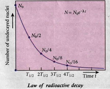
\(\mathrm{N}=\mathrm{N}_{0} \mathrm{e}^{-\lambda t}\) .....(3)
(vi) Equation (3) is called the law of radioactive decay.
(vii) Here N denotes the number of undecayed nuclei present at any time t and No denotes the number of nuclei present initially time t = 0.
(viii) From equation (3) the number of atoms is decreasing exponentially over the time. This implies that the time taken for all the radioactive nuclei to decay will be infinite.
40.
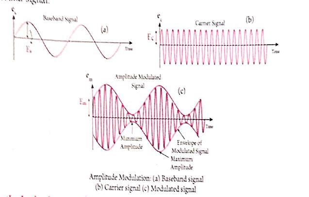
(i) If the amplitude of the carrier signal is modified according to the instantaneous amplitude of the baseband signal, then it is called amplitude modulation Here the frequency and the phase, of the carrier signal remain constant. Amplitude modulation is used in radio and TV broadcasting.
(ii) The signal shown in Figure (a) is the baseband signal that carries information. Figure(b) show the high-frequency carrier signal and Figure (c) gives amplitude modulated signal. We can see that amplitude of the carrier wave is modified in proportion to the amplitude or the baseband signal.
41.
When electron jumps from higher energy stationary orbit (m) to lower energy stationary orbit (n), emit radiation.
Wave number (or) Wave length of the emitted radiation is given by,
\(\frac{1}{\lambda}=R\left[\frac{1}{n^{2}}-\frac{1}{m^{2}}\right]=\bar{v}\)
V - Ware number; R- Rydberg constant = 1.09737 x 10⁷ m-1
m > n (where m, n are integers)
(a) Lyman series:
When electron jumps from any outer orbit to first orbit, (n = 1 and m = 2,3,4.......) the wave number or wavelength of spectral lines lies in ultra-violet region is
\(\bar{v}=\frac{1}{\lambda}=\mathrm{R}\left[\frac{1}{1^{2}}-\frac{1}{\mathrm{~m}^{2}}\right]\)
(b) Balmer series:
Wher electron jumps from any outer orbit to second orbit, (n = 2 and m = 3, 4, 5.......) the wave number or wavelength of spectral lines lies in visible region is,
\(\bar{v}=\frac{1}{\lambda}=R\left[\frac{1}{2^{2}}-\frac{1}{m^{2}}\right]\)
(c) Paschen series:
When electron jumps from any outer orbit to third orbit, (n = 3 and m = 4, 5, 6.......) the wave number or wavelength of spectral lines lies in infra red (Near IR) region is
\(\bar{v}=\frac{1}{\lambda}=R\left[\frac{1}{3^{2}}-\frac{1}{m^{2}}\right]\)
(d) Bracket series:
When electron jumps from any outer orbit to fourth orbit, (n = 4 and m = 5, 6, 7.......) the wave number or wavelength of spectral lines lies in infra red (Middle IR) region is
\(\bar{v}=\frac{1}{\lambda}=R\left[\frac{1}{4^{2}}-\frac{1}{m^{2}}\right]\)
(e) Pfund series:
When electron jumps from any outer orbit to fifth orbit, (n - 5 and m = 6, 7, 8.......) the wave number or wavelength of spectral lines lies in infra red (far IR) region is
\(\bar{v}=\frac{1}{\lambda}=R\left[\frac{1}{5^{2}}-\frac{1}{m^{2}}\right]\)
42.
Mirror Equation :
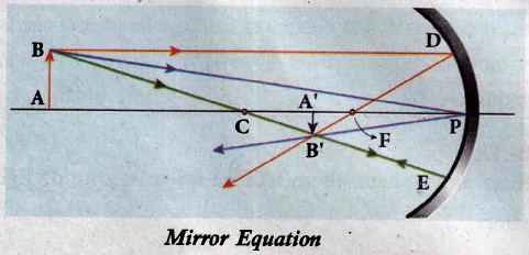
(i) AB is an object which is placed on the principal axis of a concave mirror beyond the center of curvature C. A' B' is an image which is formed between the point pole P, and the centre of curvature.
(ii) From the figure As per law of reflection, the angle of incidence ∠BPA is equal to the angle of reflection ∠B'PA'.
(iii) The triangles ∠BPA and ∠B'PA' are similar. Thus, from the rule of similar triangles,
\(\cfrac { { A }^{ ' }{ B }^{ ' } }{ AB } =\cfrac { { PA }^{ ' } }{ PA } \) ................(1)
(iv) The other set of similar triangles are, ΔDPF and ΔB'A'F. (PD is almost a straight vertical line)
\(\cfrac { { A }^{ ' }B' }{ PD } =\cfrac { A'F }{ PF } \)
(v) As, PD = AB the above equation becomes,
\(\cfrac { A'B' }{ AB } =\cfrac { A'F }{ PF } \) ......(2)
(vi) From equations (1) and (2) we can write,
\(\cfrac { PA' }{ PA } =\cfrac { A'F }{ PF } \)
(vii) As, A'F = PA' - PF, the above equation becomes,
\(\cfrac { PA' }{ PA } =\cfrac { PA'-PF }{ PF } \) .....(3)
(viii) We can apply the sign conventions for the various distances in the above equation
PA = - u, PA' = -v, PF = - f
(ix) All the three distances are negative as per sign convention, because they are measured to the left of the pole. Now, the equation (3) becomes,
\(\cfrac { -v }{ -u } =\cfrac { -v-\left( -f \right) }{ -f } \)
On further simplification,
\(\cfrac { v }{ u } =\cfrac { v-f }{ f } ;\cfrac { v }{ u } =\cfrac { v }{ f } -1 \)
Dividing either side with v,
\(\cfrac { 1 }{ u } =\cfrac { 1 }{ f } -\cfrac { 1 }{ v } \)
After rearranging,
\(\cfrac { 1 }{ v } +\cfrac { 1 }{ u } =\cfrac { 1 }{ f } \)
The above equation is called mirror equation.
Lateral magnification:
The lateral or transverse magnification is defined as the ratio of the height of the image to the height of the object. The height of the object and image are measured perpendicular to the principal axis.
Magnification (m) \(=\frac{\text { height of the image }\left(h^{\prime}\right)}{\text { height of the image }(h)} \)
\(m=\frac{h^{\prime}}{h} \) ....(1)
Applying proper sign conventions for equation,
\(\frac{A^{\prime} B^{\prime}}{A B}=\frac{P A^{\prime}}{P A} \)
\(A^{\prime} B^{\prime}=-h^{\prime}, A B=h, P A^{\prime}=-v, P A=-u \)
\(-\frac{h}{h}=\frac{-v}{-u} \)
On simplifying we get,
\(\mathrm{m}=\frac{\mathrm{h}^{\prime}}{\mathrm{h}}=-\frac{\mathrm{v}}{\mathrm{u}}\) ...(2)
Using mirror equation, we can further write the magnification as,
\(m=\frac{h^{\prime}}{h}=\frac{f-v}{f}=\frac{f}{f-u}\) ..(3)
43.
Principle:
Cathode rays are deflected in electric and magnetic fields.
By the variation of electric and magnetic fields, mass normalized charge or the specific charge (charge per unit mass) of the cathode rays is measured.
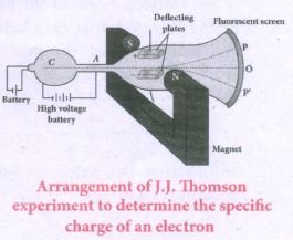
Construction and Working:
(i) Cathode rays (electron beam) produced at cathode of a highly evacuated discharge tube. Cathode rays are attracted towards anode disc A.
(ii) Pin hole in the anode disc allows only a narrow beam of cathode rays.
(iii) These cathode rays are now allowed to pass through the parallel metal plates, maintained at high voltage.
(iv) Further, discharge tube is kept in between pole pieces of magnet.
(v) Electric and magnetic fields are perpendicular to each other.
(vi) When the cathode rays strike the zinc sulphide coated screen (O), produces scintillation and hence bright spot is observed.
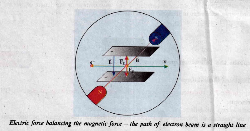
(i) Determination of velocity of cathode rays:
(a) For a fixed electric field between the plates, the magnetic field is adjusted such that the cathode rays (electron beam) strike at the original position O.
(b) This means that the magnitude of electric force is balanced by the magnitude of force due to magnetic field.
(ie) Ee = Bev
\(\Rightarrow v=\frac { E }{ B } \) ...(1)
(ii) Determination of specific charge:
(a) Since accelerated from cathode to anode, the potential energy of the electron beam at the cathode is converted into kinetic energy of the electron beam at the anode.
(b) Let V be the potential difference between anode and cathode, then the potential energy is eV.
Then from law of conservation of energy,
\(eV=\frac { 1 }{ 2 } { mv }^{ 2 } \)
\(\frac { e }{ m } =\frac { { v }^{ 2 } }{ 2V } \) ....(2)
Substituting (1) in (2),
\(\frac { e }{ m } =\frac { 1 }{ 2V } \frac { { E }^{ 2 } }{ { B }^{ 2 } } \)
By substituting known values, we get
\(\frac { e }{ m } =1.7\times { 10 }^{ 11 }{ CKg }^{ -1 }\)
The specific charge \(\frac{\mathrm{e}}{\mathrm{m}}\) is independent of (a) gas used (b) nature of the electrodes

12th Standard Syllabus & Materials
12th Standard
TN 12th Computer Applications வலையமைப்பு வடமிடல் Sample Question Papers Study Material - QB365 Set A
NEW12th Standard
TN 12th Computer Applications களப்பெயர் முறைமை (DNS) Sample Question Papers Study Material - QB365 Set A
NEW12th Standard
TN 12th Computer Applications வலையமைப்பு எடுத்துக்காட்டுகள் மற்றும் நெறிமுறைகள் Sample Question Papers Study Material - QB365 Set A
NEW12th Standard
TN 12th Computer Applications கணினி வலையமைப்பு ஓர் அறிமுகம் Sample Question Papers Study Material - QB365 Set A



Tamilnadu Stateboard 12th Standard Subjects

Maths

Chemistry
Physics

Biology

Computer Science

Business Maths and Statistics

Economics

Commerce

Accountancy

History

Computer Applications
Biology
Computer Technology
Computer Applications
Computer Science
Business Maths and Statistics
Commerce
Economics
Maths
Chemistry
Physics
Computer Technology
History
Accountancy

Tamil

English

French
Tamilnadu Stateboard Standards


