100% FREE ACCESS
10th Standard CBSE Syllabus & Materials
10th Standard CBSE
CBSE 10th Social Science ECO - Globalisation and the Indian Economy - New Model Questions Papers Study Material - QB365 Set A
NEW10th Standard CBSE
CBSE 10th Social Science ECO - Money and Credit - New Model Questions Papers Study Material - QB365 Set A
NEW10th Standard CBSE
CBSE 10th Social Science ECO - Sectors of the Indian Economy - New Model Questions Papers Study Material - QB365 Set A
NEW10th Standard CBSE
CBSE 10th Social Science ECO - Development - New Model Questions Papers Study Material - QB365 Set A
NEW10th Standard CBSE
CBSE 10th Social Science PS - Outcomes of Democracy - New Model Questions Papers Study Material - QB365 Set A
NEW10th Standard CBSE
CBSE 10th Social Science PS - Gender, Religion and Caste - New Model Questions Papers Study Material - QB365 Set A

Published on: 26/10/2025
Download CBSE Class 10th Standard CBSE Science question papers, sample papers, important questions, and previous year solved papers in PDF format. Get free study materials, NCERT solutions, and exam preparation resources for Class 10th Standard CBSE Science
Questions + Answers key
Take MCQ Science Test
1.
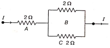
Three \(2 \Omega\) resistors A, B and C are connected as shown in figure. Each of them dissipates energy and can withstand a maximum power of 18 W without melting. Find the maximum current that can flow through the three resistors.
2.
(i) It would cost a man ₹ 3.50$ to buy 1.0 kWh of electrical energy from the main electricity board. His generator has a maximum power of 2.0 kW . The generator produces energy at this maximum power for 3 h . Calculate how much it would cost to buy the same amount of energy from the main electricity board.
(ii) A student boils water in an electric kettle for 20 min . Using the same mains supply, he wants to reduce the boiling time of water. To do so should he increase or decrease the length of the heating element? Justify your answer.
3.
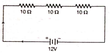
You are given three Identical \(10 \Omega\) resistors and a 12 V cell. Draw the circuit diagram to show how the resistors can be connected with the 12 V cell, so that the total heat produced in the circuit is the minimum.Competency Based Que.
4.
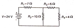
Calculate the total resistance and the total current in the circuit.
5.
There are three resistors of \(10 \Omega, 20 \Omega\) and \(30 \Omega\) Joined in parallel In a clrcuit. The potential difference across the electric clrcuit is 10 V .
(i) Draw a circuit diagram for the above case.
(ii) Find the total resistance of the combination of resistors.
(iii) Calculate the electric current drawn from the same source.
6.
Draw a schematic diagram of a circuit consisting of a battery of four dry cells of 1.5 V each, a \(2 \Omega\) resistor, a \(6 \Omega\) resistor, \(16 \Omega\) resistor and a plug key all connected in series. Put an ammeter to measure the current in the circuit and a voltmeter across the \(16 \Omega\) resistor to measure potential difference across its two ends. Use Ohm's law to determine.
(a) ammeter reading, and
(b) voltmeter reading when key is closed
7.
B1, B2 and B3 are three identical bulbs connected as shown in figure. Ammeters \(A_1, A_2\) and A3 are connected as shown in figure.
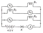
When all the bulbs glow, then the current of 3 A is recorded by ammeter A.
(i) What happens to the glow of the other two bulbs when bulb B1 gets fused?
(ii) What happens to the reading of \(A_1, A_2, A_3\) and A when the bulb B2 gets fused?
(iii) How much power is dissipated in the circuit when all the three bulbs glow together?
8.
(i) Define electric power and state its Sl unit. The commercial unit of electrical energy is known as 'unit'. Write the relation between this 'unit' and Joule.
(ii) In a house, 2 bulbs of 50 W each are used for 6 h daily and an electric geyser of 1kW is used for 1 h daily. Calculate the total energy consumed in al month of 30 days and its cost at the rate of Rs.8.00 per kWh.
9.
(i) A current of 1 A flows in a series circuit having an electric lamp and a conductor of 5 Ω when connected to a 10 V battery. Calculate the resistance of the electric lamp.
(ii) Now, if a resistance of 10Ω is connected in parallel with this series combination, then what change (if any) in current flowing through 5Ω conductor and potential difference across the lamp will take place? Give reason.
10.
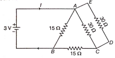
(i) Find the value of current l in the circuit given as below.
(ii) You have four resistors of 8Ω each. Show how would you connect these resistors to have effective resistance of 8 Ω?
11.
(i) How will you infer with the help of an experiment that the same current flows through every part of the circuit containing three resistors R1,R2 and R3 in series connected to a battery of V volts?
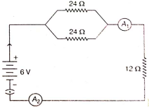
(ii) Study the following circuit and find out the (a) current in 12Ω resistor.
(b) difference in the reading of A1 and A2 if any
 2019
2019
12.
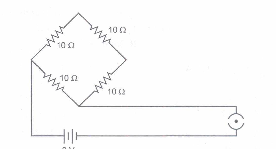
Find the current drawn from the battery by the network of four resistors shown in the figure
13.
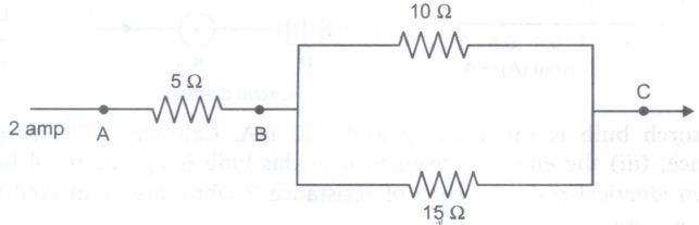
(i) Three resistors are connected as shown in the circuit diagram. Through the resistor 5 ohm, a current of 2 ampere is flowing.
(a) What is the current through the other two resistors?
(b) What is the p.d. across AB?
(c) What is the total resistance?
(ii) Can you change the set up and arrange the resistance in a manner to get the least resistance?
14.
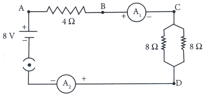
Find out the following in the electric circuit given in Figure
(a) Effective resistance of two 8 \(\Omega\) resistors in the combination
(b)Current flowing through 4 \(\Omega\) resistor
(c) Potential difference across 8 \(\Omega\) resistance
(d) Power dissipated in 4 \(\Omega\) resistor
(e) Difference in ammeter readings, if any.
15.
1. Join three resistors of different values in series. Connect them with a battery, an ammeter and a plug key, as shown in Fig.
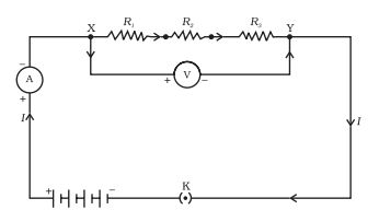
2. You may use the resistors of values like 1 Ω, 2 Ω, 3 Ω etc., and a battery of 6 V for performing this Activity.
3. Plug the key. Note the ammeter reading.
4. Change the position of ammeter to anywhere in between the resistors. Note the ammeter reading each time.
5. Do you find any change in the value of current through the ammeter?
16.
Aditya decided to complete his Physics Project. He purchased three resistors 4 Ω, 8 Ω and 8 Ω from the shop. Later he purchased a 8 V battery, switch (which works as key) and two ammeters to complete his circuit as shown below:
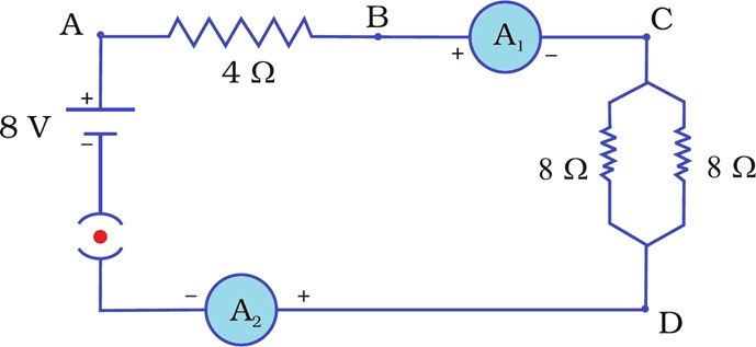
(i) Find the effective resistance of two 8 resistors in the combination
(a) 2 Ω (b) 4 Ω (c) 3 Ω (d) 5 Ω
(ii) Find the current flowing through the circuit.
(a) 1.2 A (b) 1.5 A (c) 1 A (d) 2 A
(iii) Find the potential difference across 4 Ω resistance.
(a) 2 V (b) 3 V (c) 4 V (d) 5 V
(iv) Find the power dissipated in 4 Ω resistor
(a) 2 W (b) 3 W (c) 4 W (d) 5 W
(v) Find the difference in ammeter readings.
(a) 1 (b) 2 (c) 3 (d) No difference
17.
Aditya decided to complete his Physics Project. He purchased three resistors 5 Ω, 10 Ω and 30 Ω from the shop. Later he purchased a 6 V battery, switch (which works as key) and an ammeter to complete his circuit as shown below:
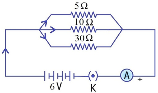
(i) Find the current through 5 Ω.
(a) 1.2 A (b) 1.5 A (c) 1 A (d) 2 A
(ii) Find the current through 10 Ω.
(a) 0.6 A (b) 0.2 A (c) 1 A (d) 0.5 A
(iii) Find the current through 30 Ω.
(a) 0.6 A (b) 0.2 A (c) 1 A (d) 0.5 A
(iv) Find the total current in the circuit.
(a) 1.2 A (b) 1.5 A (c) 1 A (d) 2 A
(v) Find the total resistance of the circuit.
(a) 2 Ω (b) 4 Ω (c) 3 Ω (d) 5 Ω
18.
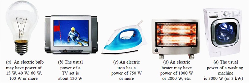
Every electrical appliance like an electric bulb, radio or fan has a label or engraved plate on it which tells us the voltage (to be applied) and the electrical power consumed by it. The power rating of an electrical appliance tells us the rate at which electrical energy is consumed by the appliance. For example, a power rating of 100 watts on the bulb means that it will consume electrical energy at the rate of 100 joules per second. If we know the power P and voltage V of an electrical appliance, then we can very easily find out the current I drawn by it. This can be done by using the formula: P = V x I.
(i) Which of the following does not represent electrical power in a circuit?
(a) I²R (b) IR² (c) VI (d)V²/R
(ii) An electric bulb is rated 220 V and 100 W. What is the resistance of the bulb?
(a) 448 Ω (b) 488 Ω (c) 484 Ω (d) 482 Ω
(iii) When the bulb in (ii) is operated on 110 V, the power consumed will be :
(a) 100 W (b) 75 W (c) 50 W (d) 25 W
(iv) The commercial unit of energy is :
(a) watt (b) watt-hour (c) kilowatt-hour (d) kilo-joule
(v) What will be the current drawn by an electric bulb of 40 W when it is connected to a source of 220 V?
(a) 0.15 A (b) 0.18 A (c) 0.20 A (d) 0.24 A
19.
In household electric circuits, the mains supply is delivered to our homes using three core cable as shown here. The cable consists of three wires, live wire, neutral wire and earth wire. The live wire is at potential difference of 220 V for the domestic supply and the potential difference between live and neutral wire is 220 volts. The live wire is connected to electric meter through a fuse or a circuit breaker of higher rating. The neutral wire is connected directly to the electric meter.
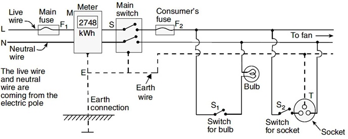
(i) Potential difference between live and neutral wire is
(a) 1000 V (b) 100 V (c) 500 V (d) 220 V
(ii) Switches are connected in household circuit with which wire?
(a) Earth wire (b) Neutral wire (c) Live wire (d) None of these
(iii) What is usual current rating of the fuse wire in the line if electric iron, geysers, room heater etc. are in use?
(a) 15 A (b) 5 A (c) 10 A (d) 25 A
(iv) For all electrical appliances which property of circuit is recommended?
(a) Earthing (b) Neutralising
(c) Connecting with fuse (d) None of these
(v) Home circuit is connected in parallel because
(a) in parallel circuit resistance is maximum
(b) in parallel circuit, if one device is damaged, then it does not affect other devices
(c) both of these
(d) none of these
20.
Derlve an expression for equivalent resistance in the following case
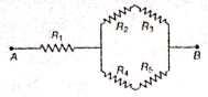
Decide which resistances are in series and parallel. Solve for series and then for parallel. Combine both the results to get the equivalent resistance.
21.
(a) State Ohm's law. Write formula for the equivalent resistance R2 of the parallel combination of three resistors of values R1, R2 and R3
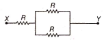
(b) Find the resistance of the following network of resistance.
1.
Given, resistance, \(R=2 \Omega\)
Maximum power, \(P_{\max }=18 \mathrm{~W}\)
Maximum current, \(I_{\max }=\) ?
As we know, \( P=I^2 R\)
\(\Rightarrow \quad I=\sqrt{\frac{P}{R}}=\sqrt{\frac{18}{2}}=3 \mathrm{~A}=I_{\max }\)
Maximum current that can flow through \(2 \Omega\) resistor is 3 A . This current divides along B and C because they are in parallel combination.
Voltage across B and C remain same and hence \(I \propto \frac{1}{R}\). Since, B and C have same resistance same current flows through them.
i.e. \(\frac{3}{2}=15, A\) flows through B and C.
2.
(i) Given, power of generator, \(P \approx 2 \mathrm{~kW}\)
Time, t=3h
therefore Energy consumed, \(E=P \times t=2 \times 3=6 \mathrm{kWh}\)
Since, cost of 1 kWh of electrical energy is ₹ 3.50.
Therefore Cost of 6 kWh of electrical energy =6 x 350 =₹ 21.0
(ii) As we know that, Heat, \(H=t^2 R t\)
Here, I is constant, so to reduce the boiling time ( f ), R should be increased.
Since, \(R=\rho \frac{l}{A}\) or \(R \propto l\)
So, the length of the heating element should be increased.
3.
As we know, \(H=I^2 R t\)
or \(H=P \times t \quad\left(\because P=I^2 R\right)\)
From above equation, we conclude that if power is minimum, then heat produced will be minimum.
So, in series combination, we get minimum power \(\left(\frac{V^2}{R}\right)\) and minimum heat. Produced in the circuit.
4.
Here, resistances $R_3$ and $R_4$ are in series, so their equivalent resistance is
\(R =R_3+R_4 =6+4=10 \Omega\)
The circuit is reduced to
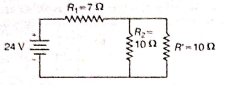
Now, resistances R2 and R' are in parallel, so their equivalent resistance,
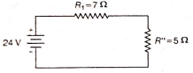
\(R^{\prime}=\frac{R_2 R^{\prime}}{R_2+R^{\prime}}=\frac{10 \times 10}{10+10}=\frac{100}{20}=5 \Omega\)
The circuit now becomes
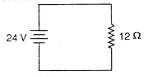
The resistances R1 and R' are in series, so their equivalent or total resistance of circuit, \(R_{\mathrm{eq}}=R_1+R^{\prime}=7+5=12 \Omega\)
The final circuit is as shown
By Ohm's law, \(I=\frac{V}{R_{\text {eq }}}=\frac{24}{12}=2 \mathrm{~A}\)
5.
(i) 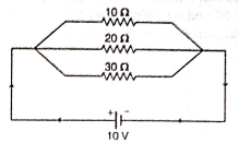
(ii) Total resistance,
\(\Rightarrow \frac{1}{R_T}=\frac{1}{R_1}+\frac{1}{R_2}+\frac{1}{R_3}\)
\(\Rightarrow \frac{1}{R_T}=\frac{1}{10}+\frac{1}{20}+\frac{1}{30} \)
\(\Rightarrow R_T=5.45 \Omega\)
(iii) Current, I=V / R
\(I =\frac{10}{R_T}=\frac{10}{5.45} =1.83 \mathrm{~A}\)
6.
Circuit diagram consisting of battery, resistors and key is
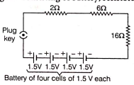
Total voltage of battery, \(V=1.5 \times 4=6.0 \mathrm{~V}\)
Equivalent resistance, \(R=2 \Omega+6 \Omega+16 \Omega=24 \Omega\)
(a) Current in the circuit (ammeter reading)
\(\Rightarrow\) using ohm's law, V=I R
\(I=\frac{V}{R}=\frac{6}{24}=0.25 \mathrm{~A}\)
(b) Voltage across the \(16 \Omega\) resistor (voltmeter reading when key is closed) in series, current is same in all resistors.
Potential across \(16 \Omega\) resistor will be, \(V=I R=0.25 \times 16=4 \mathrm{~V}\)
7.
Resistance of combination of three bulbs in parallel,
\(R_{\mathrm{eq}}=\frac{V}{I}=\frac{4.5}{3}=1.5 \Omega\)
If R is the resistance of each wire, then
\(\frac{1}{R_{e q}}=\frac{1}{R}+\frac{1}{R}+\frac{1}{R}\)or \(\frac{1}{R_{\mathrm{eq}}}=\frac{3}{R}\)
or \(R=3 R_{\mathrm{eq}}=3 \times 15=4.5 \Omega\)
Current in each bulb, \(I=\frac{V}{R}=\frac{4.5 \mathrm{~V}}{4.5 \Omega}=1 \mathrm{~A}\)
(i) When bulb B1 gets fused, then the currents in B2 and B3 remain same \(I_2=I_3=1 \mathrm{~A}\), so their glow remains unaffected.
(ii) When bulb B2 gets fused, then the current in B2 becomes zero and currents in B1 and B3 remain 1 A.
Total current,
\(I =I_1+I_2+I_3 =1+0+1=2 \mathrm{~A}\)
Current in ammeter \(A_1, I_1=1 \mathrm{~A}\)
Current in ammeter \(A_2, l_2=0\)
Current in ammeter \(\mathrm{A}_3, I_3=1 \mathrm{~A}\)
Current in ammeter \(A, I=2 \mathrm{~A}\)
(iii) When all the three bulbs are connected, then power dissipated,
\(P =\frac{V^2}{R_{\mathrm{eq}}}=\frac{(4.5)^2}{1.5} =135 \mathrm{~W}\)
8.
(i) Electric energy:
1. The energy is generated by the movement of electrons from one point to another.
2. The joule or watt-second is the fundamental unit of electrical energy.
3. A joule is defined as one ampere of current flowing through a circuit for one second when a potential difference of one volt is applied across it.
4. The kilowatt-hour (kWh), also known as the Board of Trade unit, is the commercial unit of electrical energy (B.O.T).
5. 1kwh =1000×60×60 watt-second 1kwh=3.6×10⁶W sor Joules. Generally, one kWh is called one unit.
Electric power:
1. Electrical power is defined as the rate at which an electrical circuit transfers electrical energy per unit of time. Electrical energy can be either kinetic or potential energy in this context.
2. In most cases, potential energy is taken into account, which is the energy stored as a result of the relative positions of charged particles or electric fields. P denotes electrical power, which is measured in Watts.
3. SI Unit is Watt, joule per second and Formula, P=VI Where, V is the potential difference (volts), I is the electric current.
(ii) ) Energy consumed by 2 bulbs/day = (2 x 50 x 6) = 600W - h = 0.6kWh
Total energy consumption/day = 0.6 + 1 = 1.6kWh
Total energy consumption/month = (1.6 x 30) = 48kWh,
Total cost = 48 x 8 = Rs. 384
9.
According to Ohm's law,
R=V/I
Here, R=10/1=10 Ω
Since the heater and conductor are in series, resistance of electric lamp = Total resistance- Resistance of the conductor
Hence resistance= 10−5=5 Ω
Now, when a resistance of 10 Ω is connected in parallel with this series combination, the total resistance is reduced to half of the original value and hence the total current is double the original value.
Therefore, there will be no change in the current flowing through 5Ω conductors and the potential difference across the lamp will also remain the same.
10.
(i) \(R_{A C}\) and \(R_{E D}\) are in parallel, so
\(\frac{1}{R_p^{\prime}}=\frac{1}{R_{A C}}+\frac{1}{R_{E D}}=\frac{1}{30}+\frac{1}{30}=\frac{1}{15}\)
\(\Rightarrow \quad R_p^{\prime}=15 \Omega\)
Now, \(R_p\) and \(R_{B C}\) are in series, so
\(R_s =R_p^{\prime}+R_{B C} =15+15=30 \Omega\)
Again, \(R_{A B}\) and \(R_s\) are in parallel, so
\(\frac{1}{R_p^n} =\frac{1}{R_{A B}}+\frac{1}{R_S^{\prime}} =\frac{1}{15}+\frac{1}{30}=\frac{1}{10}\)
\(\therefore \quad R_p^n =10 \Omega\)
So, current flowing through the circuit,
\(I=\frac{V}{R_p^{\prime \prime}}=\frac{3}{10}=0.3 \mathrm{~A}\)
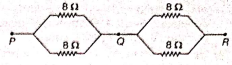
(ii) Two 8Ω resistors are connected in parallel. Two such parallel combination must be connected in series to get effective resistance of 8 Ω.
Such combination is shown as below
11.
(i) The experimental set up comprise three resistors R1,R2 and R3 of three different values such as 1 Ω, 2 Ω and 3 Ω which are connected in series.
Connect them with a battery of 6 V , an ammeter and plug key, as shown in figure
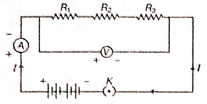
The key K is closed and the ammeter reading is recorded. Now, the position of ammeter is changed to anywhere in between the resistors again, the ammeter reading is recorded each time. It's observed that there was identical reading each time, which shows that same current flows through every part of the circuit containing three resistances in series connected to a battery.
(ii) (a) Equivalent resistance of given circuit is R, then
\(R =(24 \| 24)+12=\frac{24 \times 24}{24+24}+12\) =12+12=24 Ω
Therefore Current through $12 Ω resistor,
\(I=\frac{V}{R}=\frac{6}{24}=0.25 \mathrm{~A}\)
(b) Difference in reading of A1 and A2 = \((0.25-0.25) \mathrm{A}=0 \mathrm{~A} \)
12.
Equivalent resistance of the given network is
\(\overset { 1 }{ \underset { R }{ \_ \_ } } =\overset { { V } }{ \underset { { R }_{ 4 } }{ \_ \_ } } +\overset { 1 }{ \underset { { R }_{ 1 }+{ R }_{ 2 }+{ R }_{ 3 } }{ \_ \_ \_ \_ } } =\overset { 1 }{ \underset { 10 }{ \_ \_ } } +\overset { 1 }{ \underset { 10+10+10 }{ \_ \_ \_ \_ } } \)
\(\overset { 1 }{ \underset { 10 }{ \_ \_ } } +\overset { 1 }{ \underset { 30 }{ \_ } } =\overset { 3+1 }{ \underset { 30 }{ \_ \_ } } =\overset { 4 }{ \underset { 30 }{ \_ \_ } } \)
\(\therefore\) R = \(\overset { V }{ \underset { R }{ \_ \_ } } =\overset { 3 }{ \underset { 7.5 }{ \_ \_ } } =7.5\Omega \)
Current drawn from the battery
I =\(\overset { V }{ \underset { R }{ \_ \_ } } =\overset { 3 }{ \underset { 7.5 }{ \_ \_ } } =\overset { 30 }{ \underset { 75 }{ \_ \_ } } =\overset { 2 }{ \underset { 5 }{ \_ \_ } } \)
I = 0.4 A
13.
(i) (a) In Parallel \(I=\overset { V }{ \underset { R }{ \_ \_ } } \) or 2 x 5 = V = 10 V
For I0 \(\Omega \) resistance I = \(\overset { V }{ \underset { R }{ \_ \_ } } =\overset { 10 }{ \underset { 10 }{ \_ \_ } } \) =1A
For 15 \(\Omega \) resistance I = \(\overset { V }{ \underset { R }{ \_ \_ } } =\overset { 10 }{ \underset { 10 }{ \_ \_ } } \) = 0.7A
(b) \(I=\overset { V }{ \underset { R }{ \_ \_ } } \)
or, 2 =\(\overset { V }{ \underset { 5 }{ \_ \_ } } \)
or V=10 V
(c) Resistance in Parallel
\(\overset { 1 }{ \underset { R }{ \_ \_ } } =\overset { 1 }{ \underset { 10 }{ \_ \_ } } +\overset { 1 }{ \underset { 15 }{ \_ \_ } } =\overset { 1 }{ \underset { 30 }{ \_ \_ } } =\overset { 1 }{ \underset { 6 }{ \_ \_ } } \)
So, R= 6 \(\Omega \)
So, Total resistance across AC
= 5 + 6 = 11\(\Omega \)
(ii)
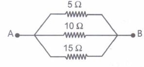
If we connect all the resistance in parallel we will get the least total resistance.
14.
(a) Since two \(8\Omega \) resistors are in parallel, their effective resistance (\({ R }_{ P }\)) is given by,
\(\frac { 1 }{ { R }_{ P } } =\frac { 1 }{ 8 } +\frac { 1 }{ 8 } +\frac { 1 }{ 4 } \) or \({ R }_{ P }=4\Omega \)
(b) Total resistance in the circuit
\(R=4\Omega +{ R }_{ P }=4\Omega +4\Omega =84\Omega \)
Current through the electric circuit
\(I=\frac { V }{ R } =\frac { 8V }{ 8\Omega } =1A\)
(c) The potential difference \(4\Omega \) resistor V
I \(=IR=1\times 4=4V\)
(d) Power dissipated in \(4\Omega \) resistor P=\({ (I) }^{ 2 }\)
\(R={ (1) }^{ 2 }(4)=4W\)
(e) There is no difference in the readings of ammeters \({ A }_{ 1 }\) and \({ A }_{ 2 }\) as same current flows through all elements in a series circuit.
15.
Resistors in series: Join 3 resistors R1, R2 and R3 of three different values in series as shown in the figure. Connect them with battery, an ammeter, a plug key. Use resistors of value 1 Ω, 2 Ω, 3 Ω etc, and a battery of 6 V for performing this activity.
Note the ammeter reading.
Change the position of ammeter to anywhere in between the resistors.
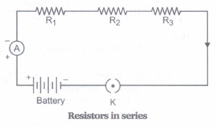
Observations: The value of current I in the ammeter is same. Let it be placed anywhere in the circuit.
Conclusion: In series combination of resistors, the value of current is the same in every part of the circuit.
16.
(i) (b) 4 Ω
(ii) (c) 1 A
(iii) (c) 4 V
(iv) (c) 4 W
(v) (d) No difference
17.
(i) (c) 24 Ω
(ii) (a) 0.25 A
(iii) (a) 5 V
(iv) (d) 1 V
(v) (b) 1.25 W
18.
(i) (b) IR²
(ii) (c) 484 Ω
(iii) (d) 25 W
(iv) (c) kilowatt-hour
(v) (b) 0.18 A
19.
(i) (d) 220 V
The potential different between live and neutral wire is 220 Volts
(ii) (c) Live wire
Switches are connected in the live wire because when the switch is in the off position, no point of the connected electrical appliance will be at higher potential (220 V).
(iii) (a) 15 A
A fuse of rating 15 A is usually used for appliance electric iron, geysers and room heater etc.
(iv) (a) Earthing
The earthing of any electrical appliance is done to protect the user from any accidental electrical shock due to leakage of current.
(v) (b) in parallel circuit if one device is damaged, then it does not affect other devices.
20.
R2 and R3 are in series, thus for this combination,
\(R^{\prime}=R_2+R_3\)
Similarly, R4 and R5 are in series.
So, \(R^{\prime \prime}=R_4+R_5\)
K' and \(R^{\prime}\) are in parallel.
R1 and R''' are in series.
\(\therefore R_{\text {eq }}=R_1+\frac{\left(R_2+R_3\right)\left(R_4+R_5\right)}{R_2+R_3+R_4+R_5}\)
\(\therefore \quad R^{\prime \prime}=\frac{R^{\prime} R^{\prime \prime}}{R^{\prime}+R^{\prime}} \)
\(R^{\prime \prime \prime}=\frac{\left(R_2+R_3\right)\left(R_4+R_5\right)}{R_2+R_3+R_4+R_5}\)
21.
(a) Ohm's law states that the current flowing through a metallic conductor is directly proportional to the potential difference applied across the ends of the metallic conductor, provided the physical conditions remain the same, i.e., temperature.
Equivalent resistance \(R_p\) of the parallel combination of three resistor of values \(R_1, R_2\) and \(R_3\) is given by
\(\frac{1}{R_p}=\frac{1}{R_1}+\frac{1}{R_2}+\frac{1}{R_3}\)
(b) Across the length \(X Y\) of wire, three resistors lies between the wire.
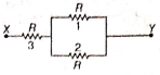
Resistors 1 and 2 are in parallel combination,
\( \frac{1}{R}=\frac{1}{R}+\frac{1}{R}=\frac{2 R}{R^2}\)
\(\Rightarrow R^{\prime}=\frac{R}{2}\) and \(R^{\prime}\) and resistor 3 are in series combination
\(R^{\prime \prime}=R+R=\frac{R}{2}+R=\frac{3 R}{2}\)

10th Standard CBSE Syllabus & Materials
10th Standard CBSE
CBSE 10th Social Science PS - Federalism - New Model Questions Papers Study Material - QB365 Set A
NEW10th Standard CBSE
CBSE 10th Social Science PS - Power Sharing - New Model Questions Papers Study Material - QB365 Set A
NEW10th Standard CBSE
CBSE 10th Social Science GEO - Manufacturing Industries - New Model Questions Papers Study Material - QB365 Set A
NEW10th Standard CBSE
CBSE 10th Social Science GEO - Minerals and Energy Resources - New Model Questions Papers Study Material - QB365 Set A



NCERT Books

Syllabus

Exam Pattern

Sample Question Papers

Previous year Question Papers

Important Notes

MCQ Practice test

NCERT Exemplers

Case study Questions

Image Based Questions

Passage based Questions

HOT Questions

Value Based Questions

Model Questions Papers
NCERT ( Book Back ) Questions

Assertion and Reason
Important Questions And Answers

CBSE 10th Standard CBSE Subjects
CBSE Standards