100% FREE ACCESS
12th Standard CBSE Syllabus & Materials
12th Standard CBSE
CBSE 12th Economics Government Budget and the Economy Previous year Question Papers Study Material - QB365 Set A
NEW12th Standard CBSE
CBSE 12th Computer Science Interface Python with MySQL - New Previous year Question Papers Study Material - QB365 Set A
NEW12th Standard CBSE
CBSE 12th Computer Science Database Concept - New Previous year Question Papers Study Material - QB365 Set A
NEW12th Standard CBSE
CBSE 12th Computer Science Data Communication - New Previous year Question Papers Study Material - QB365 Set A
NEW12th Standard CBSE
CBSE 12th Computer Science Data Structures - New Previous year Question Papers Study Material - QB365 Set A
NEW12th Standard CBSE
CBSE 12th Computer Science Functions - New Previous year Question Papers Study Material - QB365 Set A

Published on: 25/10/2025
Download CBSE Class 12th Standard CBSE Physics question papers, sample papers, important questions, and previous year solved papers in PDF format. Get free study materials, NCERT solutions, and exam preparation resources for Class 12th Standard CBSE Physics
Questions + Answers key
Take MCQ Physics Test
1.
Prove mathematically that the average value of alternating current over one complete cycle is zero.
2.
In a series LCR circuit, define the quality factor (Q) at resonance. Illustrate its significance by giving one example.
Show that power dissipated at resonance in LCR circuit is maximum.
3.
Define root mean square current. Also, obtain its expression.
4.
A 60 μF capacitor is connected to a 110 V, 60 Hz ac supply. Determine the rms value of the current in the circuit.
5.
A 15.0 µF capacitor is connected to a 220 V, 50 Hz source. Find the capacitive reactance and the current (rms and peak) in the circuit. If the frequency is doubled, what happens to the capacitive reactance and the current?
6.
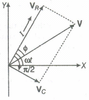
A source of AC voltage V = V0 \(sin\ \omega t\) is connected to a series combination of a resistor 'R' and a capacitor 'C. Draw the phasor diagram and use it to obtain the expression for (i) impedance of the circuit and (ii) phase angle.
7.
A charged 30\(\mu \)F capacitor is connected to a 27mH inductor. What is the angular frequency of free oscillations of the circuit?
8.
A plane electromagnetic wave of frequency 25 MHz travels in free space along the x-direction. At a particular point in space and time, \( { E } =6.3 \hat { j } \)V/m. What is B at this point?
9.
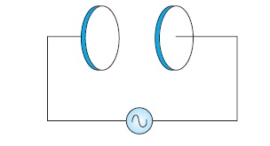
A parallel plate capacitor (Fig) made of circular plates each of radius R = 6.0 cm has a capacitance C = 100 pF. The capacitor is connected to a 230 V ac supply with a (angular) frequency of 300 rad s–1.
(a) What is the rms value of the conduction current?
(b) Is the conduction current equal to the displacement current?
(c) Determine the amplitude of B at a point 3.0 cm from the axis between the plates.
10.
Given bellow shows a series LCR circuit connected to a variable frequency 230 V source. L = 5.0 H, C = 80μF, R = 40 Ω.
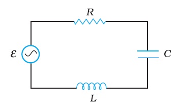
(a) Determine the source frequency which drives the circuit in resonance.
(b) Obtain the impedance of the circuit and the amplitude of current at the resonating frequency.
(c) Determine the rms potential drops across the three elements of the circuit. Show that the potential drop across the LC combination is zero at the resonating frequency.
11.
A series LCR circuit with R = 20 Ω, L = 1.5 H and C = 35 μF is connected to a variable-frequency 200 V ac supply. When the frequency of the supply equals the natural frequency of the circuit, what is the average power transferred to the circuit in one complete cycle?
12.
(a) The peak voltage of an AC supply is 300 V. What is its rms voltage?
(b) The rms value of current in an AC circuit is 10 A. What is the peak current?
13.
A 100 Ω resistor is connected to a 220 V, 50 Hz ac supply
(a) What is the rms value of current in the circuit?
(b) What is the net power consumed over a full cycle?
14.
(a) For circuits used for transporting electric power, a low power factor implies large power loss in transmission. Explain.
(b) Power factor can often be improved by the use of a capacitor of appropriate capacitance in the circuit. Explain
15.
A resistor of 200 Ω and a capacitor of 15.0 μF are connected in series to a 220 V, 50 Hz ac source. (a) Calculate the current in the circuit; (b) Calculate the voltage (rms) across the resistor and the capacitor. Is the algebraic sum of these voltages more than the source voltage? If yes, resolve the paradox.
16.
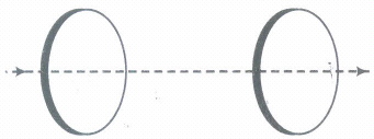
Figure shows a capacitor made of two circular plates each of radius 12 cm, and separated by 5.0 cm. The capacitor is being charged by an external source (not shown in the figure). The charging current is constant and equal to 0.15A.
(a) Calculate the capacitance and the rate of change of potential difference between the plates.
(b) Obtain the displacement current across the plates.
(c) Is Kirchhoff’s first rule (junction rule) valid at each plate of the capacitor? Explain.
17.
A sinusoidal voltage of peak value 283 V and frequency 50 Hz is applied to a series LCR circuit in which R = 3 Ω, L = 25.48 mH, and C = 796 μF. Find (a) the impedance of the circuit; (b) the phase difference between the voltage across the source and the current; (c) the power dissipated in the circuit; and (d) the power factor.
1.
Alternating current can be represented by \(\mathrm{I}=\mathrm{I}_0 \sin (2 \pi \mathrm{t} / \mathrm{T})\)
\(\mathrm{I}_{\text {avg }}=\int_0^{\mathrm{T}} \mathrm{I}_0 \sin (2 \pi \mathrm{t} / \mathrm{T}) \mathrm{dt}=0\)
2.
Q-factor of a resonant LCR circuit is defined as the ratio of the voltage drop across the inductor (or capacitor) to the applied voltage.
It is a measure of sharpness of resonance. If the resonance is less sharp, the circuit is close to resonance for a larger range Δω of frequencies and the tuning of the circuit will not be good, i.e. selectivity of the circuit will be less. In the tuning mechanism of a radio or a TV set, an antenna accepts signals from many broadcasting stations to hear or watch a particular station we tune the circuit. The tuning will be better, if Q-factor is larger. Power dissipated in a series LCR circuit \(P=I_{r m s}^{2} R\)
At resonance, XL = XC
\(Z=\sqrt{R^{2}+\left(X_{L}-X_{C}\right)^{2}}\)
It will have minimum value, i.e.Z = R.
\(\text { As } I_{\mathrm{rms}}=\frac{E_{\mathrm{rms}}}{Z}\)
Irms will have the maximum value.
So, power dissipation at resonance in an LCR circuit will be maximum (from the relation P = I2rmsR).
3.
The rms current is that value of current which produces the same amount of heat as is produced by the alternating current when flows through the same conductor for the same time period.
Let an instantaneous current I = Im sin rot is passing through a resistor R. Let it be constant for a very short duration of time dt.
Then, very small amount of heat produced is given by dH = I2R dt
Heat produced for one complete cycle is given by
\(H=\int_{o}^{T} d H=\int_{o}^{T} I^{2} R d t\)
\( \therefore \ H =\int_{0}^{T} I_{m}^{2}\left(\sin ^{2} \omega t\right) R d t=I_{m}^{2} R \int_{0}^{T} \sin ^{2} \omega t d t \)
\(=I_{m}^{2} R \int_{t=0}^{T}\left(\frac{1-\cos 2 \omega t}{2}\right) d t \)
\(H =\frac{I_{m}^{2} R}{2}\left[\int_{0}^{T} d t-\int_{0}^{T}(\cos 2 \omega t) d t\right] \)
\(=\frac{I_{m}^{2} R}{2}\left\{T-\left[\frac{\sin 2 \omega t}{2 \omega}\right]_{0}^{T}\right\} \)
\( \text { As } \omega=2 \pi / T \)
\(\mathrm{H}=\frac{I_{m}^{2} R T}{2}-\frac{I_{m}^{2} R}{2}\left[\sin 2 \times \frac{2 \pi}{T} \times T-\sin 0\right] \)
\((\because \sin 4 \pi=\sin 0=0) \)
\(\therefore \ \mathrm{H}=\frac{I_{m}^{2} R T}{2}\)
\(\)If Irms is steady current flowing through the same circuit for the same time interval T producing the same amount of heat H, then the heat produced is
\(H=I_{\mathrm{rms}}^{2} R T\) .......(ii)
Equating (i) and (ii), we get
\( \frac{I_{\mathrm{m}}^{2} R T}{2}=I_{\mathrm{rms}}^{2} R T \)
\(\therefore \frac{I_{\mathrm{m}}}{\sqrt{2}}=I_{\mathrm{rms}} \ \text { or } \ I_{\mathrm{rms}}=0.707 I_{\mathrm{m}} \)
4.
The capacitance of the capacitor in the circuit is C = 60 μ F or 60 x 10 -6 F
The source voltage is V = 110 V
The frequency of the source is ν = 60 Hz
The angular frequency can be calculated using the following relation,
ω = 2πν
The capacitive reactance in the circuit is calculated as follows:
\(X_{C}=\frac{1}{\omega C}=\frac{1}{2 \pi \nu C}=\frac{1}{2 \pi \times 60 \times 60 \times 10^{-6}} \Omega\)
Now, the RMS value of the current is determined as follows:
\(I=\frac{V}{X_{C}}=\frac{220}{2 \pi \times 60 \times 60 \times 10^{-6}}=2.49 A\)
Therefore, the RMS current is 2.49 A.
5.
The capacitive reactance is
\(X_{C}=\frac{1}{2 \pi v C}=\frac{1}{2 \pi(50 \mathrm{~Hz})\left(15.0 \times 10^{-6} \mathrm{~F}\right)}=212 \Omega\)
The rms current is
\(I=\frac{V}{X_{C}}=\frac{220 \mathrm{~V}}{212 \Omega}=1.04 \mathrm{~A}\)
The peak current is
\(i_{m}=\sqrt{2} I=(1.41)(1.04 A)=1.47 A\)
This current oscillates between +1.47A and -1.47 A, and is ahead of the voltage by π/2.
If the frequency is doubled, the capacitive reactance is halved and consequently, the current is doubled.
6.
V = V0 sin \(\omega t\)
From the diagram, by parallelogram law of vector addition. VR + VC = V
Using the Pythagorean theorem,
we get
\({V}^{2}={V }_{R }^{2 }+{ V }_{ C }^{ 2 }={(IR)}^{2}+{({IX}_{C})}^{2}\)
V2 = I2( R2 + \({ X }_{ C }^{ 2 }\) )
I = \({{V}\over{\sqrt{{R}^{2}+{ X }_{ C }^{ 2 }}}}={{V}\over{Z}}\)
where, Z = \(\sqrt{{R}^{2}+{ X }_{ C }^{ 2 }}=\sqrt{{R}^{2}+{{1}\over{{\omega}^{2}{C}^{2}}}}\)
Z = impedance.
The phase angle \(\phi\) between resultant voltage and current is given by
tan \(\phi={{{V}_{C}}\over{{V}_{R}}}={{{IX}_{C}}\over{IR}}={{{X}_{C}}\over{R}}={{1\omega/C}\over{R}}={{1}\over{\omega RC}}\)
7.
Capacitance, C = 30μF = 30 × 10−6F
Inductance, L = 27 mH = 27 × 10−3 H
Angular frequency is given as:
\({ \omega }_{ r }=\frac { 1 }{ \sqrt { LC } } =\frac { 1 }{ \sqrt { 27\times { 10 }^{ -3 }\times 30\times { 10 }^{ -6 } } } =\frac { { 10 }^{ 4 } }{ 9 } =1.1\times { 10 }^{ 3 }rad/s\)
Hence, the angular frequency of free oscillations of the circuit is 1.11 × 10³ rad/s.
8.
Using Eq, the magnitude of B is
\(B=\frac { E }{ c } \)
\(=\frac { 6.3V/m }{ 3\times { 10 }^{ 8 }m/s } =2.1\times { 10 }^{ -8 }T\)
To find the direction, we note that E is along y-direction and the wave propagates along x-axis. Therefore, B should be in a direction perpendicular to both x- and y-axes. Using vector algebra, E × B should be along x-direction.
Since, \((+\overrightarrow{\mathbf{j}}) \times(+\hat{\mathbf{k}})=\overrightarrow{\mathbf{i}}, \mathbf{B}\) is along the z-direction.
Thus, \(\mathbf{B}=2.1 \times 10^{-8} \hat{\mathbf{k}} \mathrm{T}\)
9.
Radius of each circular plate, R = 6.0 cm = 0.06 m
Capacitance of a parallel plate capacitor, C = 100 pF = 100 x 10−12 F
Supply voltage, V = 230 V
Angular frequency, ω = 300 rad s−1
(a) Rms value of conduction current, \(I=\frac{V}{X_{c}}\)
Where,
XC = Capacitive reactance
\(=\frac{1}{\omega C}\)
∴ I = V x ωC
= 230 x 300 x 100 x 10−12
= 6.9 x 10⁻⁶ A
= 6.9 μA
Hence, the rms value of conduction current is 6.9 μA.
(b) Yes, conduction current is equal to displacement current.
(c) Magnetic field is given as:
\(B=\frac{\mu_{0} r}{2 \pi R^{2}} I_{0}\)
Where,
μ0 = Free space permeability \(=4 \pi \times 10^{-7} N A^{-2}\)
I0 = Maximum value of current \(=\sqrt{2} I\)
r = Distance between the plates from the axis = 3.0 cm = 0.03 m
\(\therefore B=\frac{4 \pi \times 10^{-7} \times 0.03 \times \sqrt{2} \times 6.9 \times 10^{-6}}{2 \pi \times(0.06)^{2}}\)
= 1.63 x 10⁻¹¹ T
Hence, the magnetic field at that point is 1.63 x 10⁻¹¹ T.
10.
Given that the Inductance of the inductor in the circuit is, L = 5.0 H
Given that the Capacitance of the capacitor in the circuit is , C = 80 μH = 80 x 10 - 6 F
Given that Resistance of the resistor in the circuit, R = 40 Ω
Value of Potential of the variable voltage supply, V = 230 V
(a) We know that the Resonance angular frequency can be obtained by the following relation :
\(\omega_{r}=\frac{1}{\sqrt{L C}} \omega_{r}=\frac{1}{\sqrt{5 x 80 x 10-6}} \omega_{r}=\frac{10^{3}}{20}=50 \mathrm{rad} / \mathrm{sec}\)
Thus, the circuit encounters resonance at a frequency of 50 rad/s.
(b) We know that the Impedance of the circuit can be calculated by the following relation :
\(Z=\sqrt{R^{2}+\left(X_{L}-X_{C}\right)^{2}}\)
At resonant condition,
X L = X C
Z = R = 40 Ω
At resonating frequency amplitude of the current can be given by the following relation :
\(I_{0}=\frac{V_{0}}{Z}\)
where,
V 0 = peak voltage = \(\sqrt{2} V\)
Therefore,
\(I_{0}=\frac{\sqrt{2 V}}{Z}=\frac{\sqrt{2} \times 230}{40}=8.13 \mathrm{~A}\)
Thus, at resonant condition, the impedance of the circuit is calculated to be 40 Ω and the amplitude of the current is found to be 8.13 A
c) rms potential drop across the inductor in the circuit,
( V L ) rms = I x ω r L
Where,
\(I_{r m s}=\frac{I_{0}}{\sqrt{2}}=\frac{\sqrt{2} V}{\sqrt{2} Z}=\frac{230}{40}=\frac{23}{4} A\)
Therefore, ( V L ) rms
\(\frac{23}{4} \times 50 \times 5=1437.5 \mathrm{~V}\)
We know that the Potential drop across the capacitor can be calculated with the following relation :
\(\left(V_{c}\right)_{r m s}=I \times \frac{1}{\omega_{r} C}=\frac{23}{4} \times \frac{1}{50 \times 80 \times 10^{-6}}=1437.5 V\)
We know that the Potential drop across the resistor can be calculated with the following relation :
\(\left(V_{R}\right)_{r m s}=I R=\frac{23}{4} \times 40=230 \mathrm{~V}\)
Now, Potential drop across the LC connection can be obtained by the following relation :
V L C = I ( X L − X C )
At resonant condition,
X L = X C
V L C = 0
Therefore, it has been proved from the above equation that the potential drop across the LC connection is equal to zero at a frequency at which resonance occurs.
11.
The supply frequency and the natural frequency are equal at resonance condition in the circuit.
Given Resistance of the resistor, R = 20 Ω
Given Inductance of the inductor, L = 1.5 H
Given Capacitance of the capacitor , C = 35 μF = 30 x 10 - 6 F
An AC source with a voltage of V = 200 V is connected to the LCR circuit,
We know that the Impedance of the above combination can be calculated by the following relation,
\(Z=\sqrt{R^{2}+\left(X_{L}-X_{C}\right)^{2}}\)
At resonant condition in the circuit , X L = X C
Therefore , Z = R = 20 Ω
We know that Current in the network is given by the relation :
\(I=\frac{V}{Z}=\frac{200}{20}=10 A\)
Therefore, the average power that is being transferred to the circuit in one full cycle :
V I = 200 x 10 = 2000 W
12.
a) Given: The peak voltage of supply is 100 V.
The rms voltage is give as,
v m = 2 ×V
Where, the peak value of supply voltage is v m and its rms value is V.
By substituting the given values in the above equation, we get
300= 2 ×V V= 300 2 =212.1 V
Thus, the value of rms voltage is 212.1V.
b) Given: The rms current in an ac circuit is 10 A.
The peak current in the circuit is given as,i m = 2 ×I
Where, the peak current in an ac circuit is i m and its rms value is I.
By substituting the given values in the above equation, we get
i m = 2 ×10 =14.1 A
Thus, the value of peak current in the given ac circuit is 14.1 A.
13.
Given: The values of resistor is 100 Ω and the supply voltage is 100 V.
(a)
The RMS current is given as,
I= V R
Where, the supply voltage is V and the value of resistor is R.
By substituting the given values in the above equation, we get,
I= 220 100 =2.2 A
Thus, the value of RMS current in the conductor is 2.2 A.
(b) Power consumed over a full cycle is given as,
P=VI
Where, the supply voltage is V and the RMS current is I.
By substituting the given values in the above equation, we get
P=220×2.2 =484 W
Thus, power consumed over a full cycle is 484 W.
14.
(a) We know that P = I V cos\(\phi \) where cos\(\phi \) is the power factor. To supply a given power at a given voltage, if cos\(\phi \) is small, we have to increase current accordingly. But this will lead to large power loss (I2R) in transmission.
(b) Suppose in a circuit, current I lags the voltage by an angle \(\phi \). Then power factor \(\phi \) = R/Z.
We can improve the power factor (tending to 1) by making Z tend to R. Let us understand, with the help of a phasor diagram.
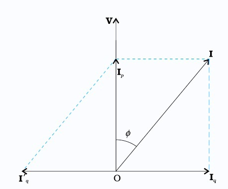
how this can be achieved. Let us resolve I into two components. Ip along the applied voltage V and Iq perpendicular to the applied voltage. Iq as you have learnt in Section 7.7, is called the wattless component since corresponding to this component of current, there is no power loss. IP is known as the power component because it is in phase with the voltage and corresponds to power loss in the circuit.
It’s clear from this analysis that if we want to improve power factor, we must completely neutralize the lagging wattless current Iq by an equal leading wattless current I'q. This can be done by connecting a capacitor of appropriate value in parallel so that Iq and I′q cancel each other and P is effectively Ip V.
15.
Given
R = 200Ω, C = 15.0μF = 15.0 x 10⁻⁶F
V = 220 V, ν = 50 Hz
(a) In order to calculate the current, we need the impedance of the circuit. It is
\(Z=\sqrt{R^{2}+X_{C}^{2}}=\sqrt{R^{2}+(2 \pi v C)^{-2}}\)
\(=\sqrt{(200 \Omega)^{2}+\left(2 \times 3.14 \times 50 \times 15.0 \times 10^{-6} \mathrm{~F}\right)^{-2}}\)
\(=\sqrt{(200 \Omega)^{2}+(212.3 \Omega)^{2}}\)
= 291.67Ω
Therefore, the current in the circuit is
\(I=\frac{V}{Z}=\frac{220 \mathrm{~V}}{291.5 \Omega}=0.755 \mathrm{~A}\)
(b) Since the current is the same throughout the circuit, we have
\(V_{R}=I R=(0.755 \mathrm{~A})(200 \Omega)=151 \mathrm{~V}\)
\(V_{C}=I X_{C}=(0.755 \mathrm{~A})(212.3 \Omega)=160.3 \mathrm{~V}\)
The algebraic sum of the two voltages, VR and VC is 311.3 V which is more than the source voltage of 220 V. How to resolve this paradox? As you have learnt in the text, the two voltages are not in the same phase. Therefore, they cannot be added like ordinary numbers. The two voltages are out of phase by ninety degrees. Therefore, the total of these voltages must be obtained using the Pythagorean theorem:
\(V_{R+C}=\sqrt{V_{R}^{2}+V_{C}^{2}}\)
= 220 V
Thus, if the phase difference between two voltages is properly taken into account, the total voltage across the resistor and the capacitor is equal to the voltage of the source.
16.
A) Step 1: Find capacitance between the two plates. Formula used: \(C=\frac{\varepsilon_0 A}{d}\)
Given, Distance between the plates, d=5 cm=0.05m
Radius of each circular plate,
r = 12cm = 0.12m
Now, area of each plate, A=πr2
A = 3.14 (0.12)2 = 0.045216 m2
Capacitance between two plates,
\(C=\frac{\varepsilon_0 A}{d}\)
Here, ϵ0 = permittivity of free space =8.85 × 10⁻¹²C2/Nm2
C=8.85×10−12× 0.045216/0.05
C = 8.0032×10⁻¹²
Step 2: Find change of potential difference between the two plates. Formula used: q = CV
Given, charging current, I=0.15A
Charge on each plate, q=CV
Where, V = Potential difference across the plates
Differentiating both sides with respect to time (t), we get,
\(\begin{array}{rlr} \Rightarrow \quad \frac{d q}{d t} & =C \cdot \frac{d V}{d t} \end{array}\)
\(\begin{array}{rlr} \Rightarrow \quad I & =C \cdot \frac{d V}{d t} \end{array}\) \(\left[\because \frac{d q}{d t}=I\right]\)
\(\begin{array}{rlr} \Rightarrow \quad \frac{d V}{d t} & =\frac{I}{C}=\frac{0.15}{8.0032
\times 10^{-12}} \end{array}\)
Step 2 : Find change of potential difference between teh two plates.
Formula used: q = CV
dV/dt= 1.87 × 10¹⁰V/s
The rate of change of potential difference between the plates is 1.87×10¹⁰V/s
Final answer : C=8.0032×10−12,1.87×1010V/s
B) Formula used: id=ϵ0(dϕEdt)
Given, charging current or conduction current, I=0.15 A
The displacement current across the plates, id=ϵ0(dϕE/dt)
Using Gauss's law, electric flux ϕE=qϵ0
id=ϵ0(1dq/ϵ0dt)=dq/dt
id=dqdt = conduction current =0.15A
Hence, the displacement current, id is 0.15 A.
Final answer : 0.15 A.
C) Kirchhoff’s first rule (junction rule):
It states that at a junction in an electrical circuit, the sum of currents flowing into the junction is equal to the sum of currents flowing out of the junction.
Kirchhoff’s first rule is valid at each plate of the capacitor provided that we consider the current to be the sum of both conduction and displacement currents.
17.
(a) To find the impedance of the circuit, we first calculate \(X_{\mathrm{L}}\) and \(X_{\mathrm{C}}\).
\( X_L=2 \pi v L \)
\(=2 \times 3.14 \times 50 \times 25.48 \times 10^{-3} \Omega=8 \Omega \)
\(X_c=\frac{1}{2 \pi v C} =\frac{1}{2 \times 3.14 \times 50 \times 796 \times 10^{-6}}=4 \Omega\)
Therefore.
\(Z =\sqrt{R^2+\left(X_L-X_C\right)^2}=\sqrt{3^2+(8-4)^2} =5 \Omega\)
\(Z =\sqrt{R^2+\left(X_L-X_C\right)^2}=\sqrt{3^2+(8-4)^2} =5 \Omega\)
(b) Phase difference, \(\phi=\tan ^{-1} \frac{X_C-X_L}{R}\)
\(=\tan ^{-1}\left(\frac{4-8}{3}\right)=-53.1^{\circ}\)
Since \(\phi\) is negative, the current in the circuit lags the voltage across the source.
(c) The power dissipated in the circuit is
\(P=I^2 R\)
Now, \(I=\frac{i_m}{\sqrt{2}}=\frac{1}{\sqrt{2}}\left(\frac{283}{5}\right)=40 \mathrm{~A}\)
Therefore, \(P=(40 \mathrm{~A})^2 \times 3 \Omega=4800 \mathrm{~W}\)
(d) Power factor \(=\cos \phi=\cos \left(-53.1^{\circ}\right)=0.6\)

12th Standard CBSE Syllabus & Materials
12th Standard CBSE
CBSE 12th Computer Science Python Revision Tour I - New Previous year Question Papers Study Material - QB365 Set A
NEW12th Standard CBSE
CBSE 12th Business Studies Planning Important Questions And Answers Study Material - QB365 Set A
NEW12th Standard CBSE
CBSE 12th Business Studies Business Environment Important Questions And Answers Study Material - QB365 Set A
NEW12th Standard CBSE
CBSE 12th Business Studies Principles of Management Important Questions And Answers Study Material - QB365 Set A



NCERT Books

Syllabus

Exam Pattern

Sample Question Papers

Previous year Question Papers

Important Notes

MCQ Practice test

NCERT Exemplers

Case study Questions

Image Based Questions

Passage based Questions

HOT Questions

Value Based Questions

Model Questions Papers
NCERT ( Book Back ) Questions

Assertion and Reason
Important Questions And Answers

CBSE 12th Standard CBSE Subjects
CBSE Standards