100% FREE ACCESS
12th Standard CBSE Syllabus & Materials
12th Standard CBSE
CBSE 12th Economics Government Budget and the Economy Previous year Question Papers Study Material - QB365 Set A
NEW12th Standard CBSE
CBSE 12th Computer Science Interface Python with MySQL - New Previous year Question Papers Study Material - QB365 Set A
NEW12th Standard CBSE
CBSE 12th Computer Science Database Concept - New Previous year Question Papers Study Material - QB365 Set A
NEW12th Standard CBSE
CBSE 12th Computer Science Data Communication - New Previous year Question Papers Study Material - QB365 Set A
NEW12th Standard CBSE
CBSE 12th Computer Science Data Structures - New Previous year Question Papers Study Material - QB365 Set A
NEW12th Standard CBSE
CBSE 12th Computer Science Functions - New Previous year Question Papers Study Material - QB365 Set A

Published on: 25/10/2025
Download CBSE Class 12th Standard CBSE Physics question papers, sample papers, important questions, and previous year solved papers in PDF format. Get free study materials, NCERT solutions, and exam preparation resources for Class 12th Standard CBSE Physics
Questions + Answers key
Take MCQ Physics Test
1.
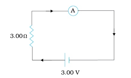
In the circuit the current is to be measured. What is the value of the current if the ammeter shown
(a) is a galvanometer with a resistance RG = 60.00 Ω;
(b) is a galvanometer described in (a) but converted to an ammeter by a shunt resistance rs = 0.02 Ω;
(c) is an ideal ammeter with zero resistance?
2.
A 15.0 µF capacitor is connected to a 220 V, 50 Hz source. Find the capacitive reactance and the current (rms and peak) in the circuit. If the frequency is doubled, what happens to the capacitive reactance and the current?
3.
An electric dipole is kept in a uniform electric field. Derive an expression for the net torque acting on it and write its direction. State the conditions under which the dipole is in
(i) stable equilibrium
(ii) unstable equilibrium.
4.
Write the expression for the electrostatic energy stored in a capacitor of capacitance 'C' and having charge 'Q'. How will the
(i) energy stored and
(ii) the electric field inside the capacitor be affected when it is completely filled with a dielectric material of dielectric constant 'K'?
5.
A solenoid 50 cm long has 4 layers of winding of 350 turns each. The radius of the lowest layer is 1.4 cm. If the current carried is 6.0 A, estimate the magnitude of B
(a) near the centre of the solenoid on its axis, and off its axis.
(b) near its ends on its axis.
(c) outside the solenoid near its centre.
6.
(a) Three resistors \(1\Omega ,2\Omega \ and\ 3\Omega \) are combined in series. What is the total resistance of the combination?
(b) If the combination is connected to a battery of emf 12 V and negligible internal resistance, obtain the potential drop across each resistor.
7.
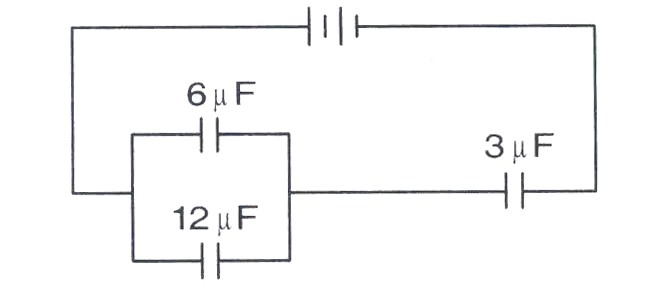
In the arrangement of capacitors shown here,the energy stored \(6\mu F\)capacitor is E. Find the following:
Energy stored in the \(12\mu F\) capacitor
Energy stored in the \(3\mu F\) capacitor
Total energy drawn from the battery.
8.
A \(100\mu F\) capacitor in series with a \(40\Omega \) is connected to a 110 V, 60 Hz supply.
(a) What is the maximum current in the circuit?
(b) What is the time lag between the current maximum and the voltage maximum?
9.
At room temperature (27.0oC) the resistance of a heating element is 100 \(\Omega\). What is the temperature of the element if the resistance is found to be 117\(\Omega\) given that the temperature coefficient of the material of the resistor is 1.70 x 10⁻⁴ oC-1.
10.
The magnetic flux through a coil perpendicular to the plane is given by \(\phi=5 t^{3}+4 t^{2}+2 t\). Calculate induced emf through the coil at t = 2s.
11.
What is the magnitude of the equatorial and axial fields due to a bar magnet of length 5.0 cm at a distance of 50 cm from its mid-point? The magnetic moment of the bar magnet is 0.40 A m2, the same as in.
12.
The instantaneous value of current in an AC circuit is \(I=2\sin { \left( 100\pi t+\pi /3 \right) A } \). At what first time, the current will be maximum?
13.
Write the expression for Lorentz magnetic force on a particle of charge q moving with velocity V in a magnetic field B. Show that no work is done by this force on the charged particle.
14.
In which orientation is the force experienced by a current-carrying conductor placed in a magnetic field (i) minimum (ii) maximum ?
15.
Define the term mobility of charge carriers in a conductor. Write its SI unit.
16.
Three capacitors each of capacitance 9 pF are connected in series.
(a) What is the total capacitance of the combination?
(b) What is the potential difference across each capacitor, if the combination is connected to a 120 V supply?
17.
The four arms of a Wheatstone bridge Figure have the following resistances:
AB = 100Ω, BC = 10Ω, CD = 5Ω, and DA = 60Ω.
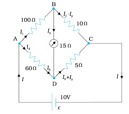
A galvanometer of 15Ω resistance is connected across BD. Calculate the current through the galvanometer when a potential difference of 10 V is maintained across AC.
18.
(a) Obtain the expression for the magnetic energy stored in a solenoid in terms of magnetic field B, area A and length l of the solenoid.
(b) How does this magnetic energy compare with the electrostatic energy stored in a capacitor?
19.
A solenoid has a core of a material with relative permeability 400. The windings of the solenoid are insulated from the core and carry a current of 2A. If the number of turns is 1000 per metre, calculate (a) H, (b) M, (c) B and (d) the magnetising current Im.
20.
Derive an expression for the impedance of a series LCR circuit connected to an AC supply of variable frequency.
Plot a graph showing variation of current with the frequency of the applied voltage. Explain briefly how the phenomenon of resonance in the circuit can be used in the tuning mechanism of a radio or a TV set.
21.
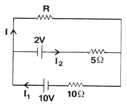
Two cells of voltages 10V and 2V and internal resistances \(10\Omega\ and\ 5\Omega \) respectively are connected in parallel with the positive end of 10V battery connected to negative pole of 2V battery. Find the effective voltage and effective resistance of the combination.
22.
A 15Ω resistor, an 80 mH inductor and a capacitor of capacitance Care connected in series with a 50 Hz AC source. If the source voltage and current in the circuit are in phase, then the value of capacitance is
100 µF
127 µF
142 µF
160 µF
23.
A magnet of dipole moment M is aligned in equilibrium position in a magnetic field of intensity B. The work done to rotate it through an angle θ with the magnetic field is
MB sin θ
MB cos θ
MB (1 - cos θ)
MB(l - sin θ)
24.
The maximum current that can be measured by a galvanometer of resistance 40 Ω is 10 mA. It is converted into voltmeter that can read upto 50 V. The resistance to be connected in the series with the galvanometer is
2010 Ω
4050 Ω
5040 Ω
4960 Ω
25.
The Wheatstone bridge and its balance condition provide a practical method for determination of an
known resistance
unknown resistance
Both (a) and (b)
None of the above
26.
Two magnets have the same length and the same pole strength. But one of the magnets has a small hole at its centre. Then,
both have equal magnetic moment
one with hole has small magnetic moment
one with hole has large magnetic moment
one with hole loses magnetism through the hole
27.
If an electric dipole of moment \(\vec P\) isplaced in electric field of strergth \(\vec E\), then which of the following gives the ential energy of the dipole?
\(\vec P.\vec E\)
\(-\vec P.\vec E\)
\(|\vec P\times\vec E|\)
None of the above
28.
What is the resistance across A and B in the fig?
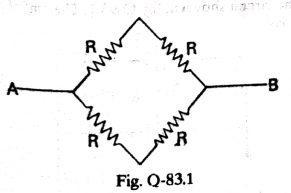
\(\frac{R}{2}\)
R
2R
4R
29.
In an alternating current circuit consisting of elements in series, the current increases on increasing the frequency of supply. Which of the following elements are likely to constitute the circuit?
Only resistor
Resistor and an inductor
Resistor and a capacitor
Only a capacitor
30.
A positive charge is moving towards an observer. The direction of magnetic induction lines is
clockwise
anticlockwise
right
left
31.
The correct relation between electric intensity E and electric potential V is
\(E=-{dV\over dr}\)
\(E={dV\over dr}\)
\(V=-{dE\over dr}\)
\(V={dE\over dr}\)
32.
At a particular point, electric field depends upon
Source charge Q only
test charge qo only
both Q and q0
neither Q nor qo
33.
When number of turns of a soleniod is doubled, its self inductance becomes k times, where k =
2
1
8
4
34.
Assertion (A) : An induced emf is generated when magnet is withdrawn from the solenoid.
Reason (R) : The relative motion between magnet and solenoid induces emf
Codes:
(a) Both A and R are true and R is the correct explanation of A
(b) Both A and R are true but R is NOT the correct explanation of A
(c) A is true but R is false
(d) A is false and R is also false
35.
Assertion: The current flowing through a conductor is directly proportional to the drift velocity.
Reason: As the drift velocity increases the current following through the conductor decreases
Codes:
(a) Both A and R are true and R is the correct explanation of A
(b) Both A and R are true but R is NOT the correct explanation of A
(c) A is true but R is false
(d) A is false and R is also false
36.
Assertion (A) : Electric potential of the earth is zero.
Reason (R) : The electric field due to the earth is zero.
Codes:
(a) Both A and R are true and R is the correct explanation of A
(b) Both A and R are true but R is NOT the correct explanation of A
(c) A is true but R is false
(d) A is false and R is also false
37.
Ampere's law gives a method to calculate the magnetic field due to given current distribution. According to it, the circulation \(\oint \vec{B} \cdot d \vec{l}\) of the resultant magnetic field along a closed plane curve is equal to \(\mu_{0}\) times the total current crossing the area bounded by the closed curve provided the electric field inside the loop remains constant. Ampere's law is more useful under certain symmetrical conditions. Consider one such case of a long Straight wire with circular cross-section (radius R) carrying current I uniformly distributed across this cross-section.
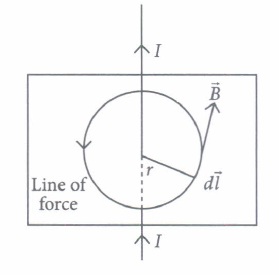
(i) The magnetic field at a radial distance r from the centre of the wire in the region r > R, is
| \(\text { (a) } \frac{\mu_{0} I}{2 \pi r}\) | \(\text { (b) } \frac{\mu_{0} I}{2 \pi R}\) | \(\text { (c) } \frac{\mu_{0} I R^{2}}{2 \pi r}\) | \(\text { (d) } \frac{\mu_{0} I r^{2}}{2 \pi R}\) |
(ii) The magnetic field at a distance r in the region r < R is
| \(\text { (a) } \frac{\mu_{0} I}{2 r}\) | \(\text { (b) } \frac{\mu_{0} I r^{2}}{2 \pi R^{2}}\) | \(\text { (c) } \frac{\mu_{0} I}{2 \pi r}\) | \(\text { (d) } \frac{\mu_{0} I r}{2 \pi R^{2}}\) |
(iii) A long straight wire of a circular cross section (radius a) carries a steady current I and the current I is uniformly distributed across this cross-section. Which of the following plots represents the variation of magnitude of magnetic field B with distance r from the centre of the wire?

(iv) A long straight wire of radius R carries a steady current I. The current is uniformly distributed across its cross-section. The ratio of magnetic field at R/2 and 2R is
| \(\text { (a) } \frac{1}{2}\) | (b) 2 | \(\text { (c) } \frac{1}{4}\) | (d) 1 |
(v) A direct current I flows along the length of an infinitely long straight thin walled pipe, then the magnetic field is
| (a) uniform throughout the pipe but not zero | (b) zero only along the axis of the pipe |
| (c) zero at any point inside the pipe | (d) maximum at the centre and minimum at the edges. |
38.
Wheatstone bridge is an arrangement of four resistances P, Q, Rand S connected as shown in the figure. Their values are so adjusted that the galvanometer G shows no deflection. The bridge is then said to be balanced when this condition is achieved happens. In the setup shown here, the points Band D are at the same potential and it can be shown that \(\frac{P}{Q}=\frac{R}{S}\)
This is called the balancing condition. If any three resistances are known, the fourth can be found.
The practical form of Wheatstone bridge is slide wire bridge or Meter bridge. Using this the unknown resistance can be determined as \(S=\left(\frac{100-l}{l}\right) \times R\) ,where I is the balancing length of the Meter bridge.
(i) In a Wheatstone bridge circuit, \(P=5 \Omega, Q=6 \Omega, R=10 \Omega\) and \(S=5 \Omega\) What is the value of additional resistance to be used in series with S, so that the bridge is balanced?
| \(\text { (a) } 9 \Omega\) | \(\text { (b) } 7 \Omega\) | \(\text { (c) } 10 \Omega\) | \(\text { (d) } 5 \Omega\) |
(ii) A Wheatstone bridge consisting of four arms of resistances P, Q, R, S is most sensitive when
| (a) all the resistances are equal |
| (b) all the resistances are unequal |
| (c) the resistances P and Q are equal but R > > P and S > > Q |
| (d) the resistances P and Q are equal but R < < P and S < < Q |
(iii) When a metal conductor connected to left gap of a meter bridge is heated, the balancing point
| (a) shifts towards right | (b) shifts towards left | (c) remains unchanged | (d) remains at zero |
(iv) The percentage error in measuring resistance with a meter bridge can be minimized by adjusting the balancing point close to
| (a) 0 | (b)·20cm | (c) 50cm | (d) 80cm |
(v) In a meter bridge experiment, the ratio ofleft gap resistance to right gap resistance is 2 : 3. The balance point from left is
| (a) 20 cm | (b) 50 cm | (c) 40 cm | (d) 60 cm |
1.
(a) Total resistance in the circuit is,
RG+3 = 63 Ω. Hence, I = 3 / 63 = 0.048 A.
(b) Resistance of the galvanometer converted to an ammeter is,
\(\frac{R_{G} r_{s}}{R_{G}+r_{s}}=\frac{60 \Omega \times 0.02 \Omega}{(60+0.02) \Omega}=0.02 \Omega\)
Total resistance in the circuit is,
0.02Ω + 3Ω = 3.02Ω . Hence, I = 3 / 3.02 = 0.99 A.
(c) For the ideal ammeter with zero resistance,
I = 3 / 3 = 1.00 A
2.
The capacitive reactance is
\(X_{C}=\frac{1}{2 \pi v C}=\frac{1}{2 \pi(50 \mathrm{~Hz})\left(15.0 \times 10^{-6} \mathrm{~F}\right)}=212 \Omega\)
The rms current is
\(I=\frac{V}{X_{C}}=\frac{220 \mathrm{~V}}{212 \Omega}=1.04 \mathrm{~A}\)
The peak current is
\(i_{m}=\sqrt{2} I=(1.41)(1.04 A)=1.47 A\)
This current oscillates between +1.47A and -1.47 A, and is ahead of the voltage by π/2.
If the frequency is doubled, the capacitive reactance is halved and consequently, the current is doubled.
3.
(i) When θ = 0; ፔ = O and p and E are parallel and the dipole is in a position of stable equilibrium.
(ii) When θ = 180°, ፔ = 0 and p and E are anti-parallel and the dipole is in a position of unstable equilibrium.
4.
When a capacitor is charged by a battery, work is done by the charging battery at the expense of its chemical energy.
This work is stored in the capacitor in the form of electrostatic potential energy. Consider a capacitor of capacitance C. Initial charge on capacitor is zero. Initial potential difference between capacitor plates = zero. Let a charge Q be given to it in small steps. When charge is given to capacitor, the potential difference between its plates increases. Let at any instant when charge on capacitor be q, the potential difference between its plates V = q/C.
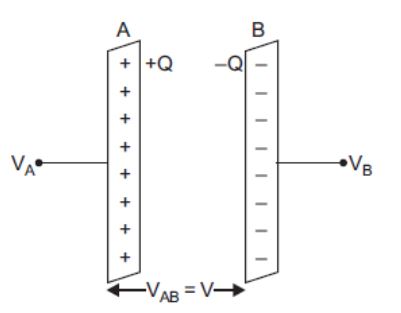
Now work done in giving an additional infinitesimal charge dq to capacitor
dW = Vdq = q/C(dq)
The total work done in giving charge from 0 to Q will be equal to the sum of all such infinitesimal works, which may be obtained by integration. Therefore total work
\(\begin{aligned}
W & =\int_0^Q V d q=\int_0^Q \frac{q}{C} d q \\
\end{aligned}\)
\(\begin{aligned}
=\frac{1}{C}\left[\frac{q^2}{2}\right]_0^Q=\frac{1}{C}\left(\frac{Q^2}{2}-\frac{0}{2}\right)=\frac{Q^2}{2 C}
\end{aligned}\)
If V is the final potential difference between capacitor plates, then Q =CV
\(\therefore \quad W=\frac{(C V)^2}{2 C}=\frac{1}{2} C V^2=\frac{1}{2} Q V\)
This work is stored as electrostatic potential energy of capacitor i.e.,
Electrostatic potential energy,
U=Q2/2C = 1/2(CV2) = 1/2(QV)
When battery is disconnected (i) Energy stored will be decreased. The energy becomes,
\(U=\frac{Q_0^2}{2 C}=\frac{Q_0^2}{2 K C_0}=\frac{U_0}{K}\)
Thus, energy is reduced to1/K times the initial energy.
(ii) In the presence of dielectric the electric field is reduced to E =E/K= 0.
5.
The ratio of length to radius of the solenoid is quite large (about 35). Therefore, to estimate B approximately, we can use the exact result for a closely wound infinitely long solenoid.
(a) At the centre or near it,
\(B={ \mu }_{ 0 }nI\)
Where n is the number of turns per unit length.
Note 1. the radius of the wire does not enter this equation. Therefore, to get n, simply multiply number of turns per layer and divide the product by the length of the solenoid.
\(n=\frac { 350\times 4 }{ 0.50 } =2800{ m }^{ -1 }\)
Now \(I=6.0A,\)
and \({ \mu }_{ 0 }=4\pi \times { 10 }^{ -7 }T{ mA }^{ -1 },\)
Which gives \(B=2.1\times { 10 }^{ -2 }T\)
Note 2. This estimate of B is for both on and off the axis, since for an infinitely long solenoid, the internal field near the centre is uniform over the entire cross-section.
(b) At the end of the solenoid,
\(B=\frac { { \mu }_{ 0 }nI }{ 2 }\)
\(=1.05\times { 10 }^{ -2 }T\)
(c) The outside field near the centre of long solenoid is negligible to the internal field.
6.
Given
\({ R }_{ 1 }=1\Omega ,{ R }_{ 2 }=2\Omega ,{ R }_{ 3 }=3\Omega \)
(a) Total resistance of series combination
\({ R }_{ s }={ R }_{ 1 }+{ R }_{ 2 }+{ R }_{ 3 }\)
\({ R }_{ s }\) = 1 + 2 + 3 = \(6\Omega \)
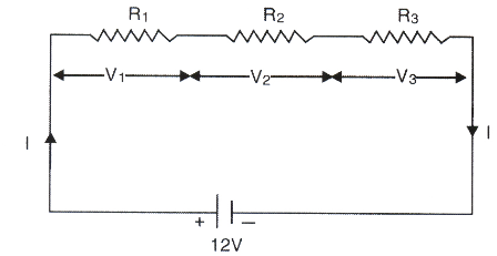
(b) Since E = I (R + r)
I = \(\frac { E }{ { R }_{ s }+0 } =\frac { E }{ { R }_{ s } } =2A\)
\({ V }_{ 1 }={ IR }_{ 1 }=2\times 1=2V\)
\({ V }_{ 2 }={ IR }_{ 2 }=2\times 2=4V\)
\({ V }_{ 3 }={ IR }_{ 3 }=2\times 3=6V\)
7.
Energy stored in 6 μF capacitor = E
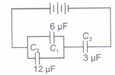
\( \therefore \ \frac{1}{2} C_{1} V_{1}^{2}=E \Rightarrow V_{1}^{2}=\frac{2 E}{C_{1}}=\frac{E}{3} \)
\(\because C_{1} \text { and } C_{2} \text { are in parallel, } \therefore V_{1}^{2}=V_{2}^{2}=\frac{E}{3} \)
Now, \(C_{12}=6+12=18 \mu \mathrm{F}\)
\( \therefore \text { Charge on } C_{12}=q_{12}=C_{12} . V_{12}=18 \times \sqrt{\frac{E}{3}} \)
\(\therefore \text { Charge on } C_{3}=q_{12}=18 \sqrt{\frac{E}{3}} \)
(a) Now, energy stored in 12 μF capacitor
\(=\frac{1}{2} C_{2} V_{1}^{2}=\frac{1}{2} \times 12 \times \frac{E}{3}=2 E\)
(b) Energy stored in 3 μF capacitor
\(=\frac{q_{3}^{2}}{2 C_{3}}=\frac{1}{2} \times\left(\frac{18}{3}\right)^{2} E=18 E\)
\((c) \because C_{e q}=\left(\frac{18 \times 3}{18+3}\right) \mu \mathrm{F}=\frac{18}{7} \mu \mathrm{F}, Q=18 \sqrt{\frac{E}{3}}\)
Energy drawn from the battery,
\(U=\frac{Q^{2}}{2 C_{e q}}=\frac{18 \times 18 \times E \times 7}{3 \times 18}=42 E\)
8.
(a) Io = 3.23A
(b) 1.55ms
9.
Given, resistance of heating element at temperature 27°C,
R27 = 100 \(\Omega\)
Resistance of heating element at temperature t°C,
Rt = 117 \(\Omega\)
\(\alpha\)=1.70 \(\times\)10-4 °C-1, t = ?
By using the formula of temperature coefficient of resistance,
\(\alpha=\frac{R_2-R_1}{R_1\left(t_2-t_1\right)}\) ...(i)
Here, R1 = Rt, R1 = R27, t2 = t and t1 = 27°C
Such that, \(\alpha=\frac{R_t-R_{27}}{R_{27}(t-27)}\)
Substituting given values in Eq. (i), we get
\(\begin{aligned} 1.70 \times 10^{-4} & =\frac{117-100}{100(t-27)} \\ \end{aligned}\)
\(\begin{aligned} \text { or } \quad t-27 & =\frac{17}{100 \times 1.70 \times 10^{-4}} \end{aligned}\)
or t = 1000 + 27 = 1027°C
10.
As we know that, \(e=\frac{d \phi}{d t}\)
As, \(\phi =5{t}^{3}+4{t}^{2}+2t\)
So, \(e=15{t}^{2}+8t+2\)
For \(t=2s, \ e=15\times {2}^{2}+8\times 2+2\)
= 60 + 16 + 2 = 78 V
11.
\(B_{E}=\frac{\mu_{0} m}{4 \pi r^{3}}=\frac{10^{-7} \times 0.4}{(0.5)^{3}}=\frac{10^{-7} \times 0.4}{0.125}=3.2 \times 10^{-7} \mathrm{~T}\)
From Eq \(B_{A}=\frac{\mu_{0} 2 m}{4 \pi r^{3}}=6.4 \times 10^{-7} \mathrm{~T}\)
12.
\(I=2 \sin (100 \pi t+\pi / 3) A\)
Since, the relation between current and time gives us
\(
\frac{2 \pi t}{T}=100 \pi t \\
\therefore T=\frac{2 \pi}{100 \pi}=\frac{1}{50} s
\)
\(t=\frac{T}{4}=\frac{1}{50 \times 4}=\frac{1}{200} \mathrm{~s}\)
13.
Lorentz magnetic force on a moving charged particle in the magnetic field is
\(\overset { \rightarrow }{ F } =q\left( \overset { \rightarrow }{ v } \times \overset { \rightarrow }{ B } \right) \)
This force is acting perpendicular to the plane containing \(\overset { \rightarrow }{ v } \) and \(\overset { \rightarrow }{ B } \) , and is directed as given by Right Hand rule. Since work done,
\(\overset { \rightarrow }{ W } =\overset { \rightarrow }{ F } .\overset { \rightarrow }{ s } =Fscos\theta ,\)
where is displacement of charged particle in magnetic field. Here, angle \(\theta ={ 90 }^{ o }\) , so
W = Fs cos 90o
= 0.
14.
Force on a current carrying conductor in magnetic field, \(F=IlB{ sin }\theta \) |
(i) Force F will be minimum if \({ sin }\theta =0\) or \(\theta ={ 0 }^{ o }\) or 180o , i.e.,the linear conductor carrying current is parallel or antiparallel to the direction of magnetic field.
(ii) ) Force F will be maximum if \({ sin }\theta ={ 1 }\) or \(\theta ={ 90 }^{ o }\) , i.e.,the linear conductor carrying current is perpendicular to the direction of uniform magnetic field.
15.
Mobility of charge carriers inside conductor is defined as the magnitude of drift velocity of charge per unit electric field applied.
SI unit of mobility is m2s-1V-1 or ms-1N-1C.
16.
There are three capacitors cach of capacitance 9 pF.
\(\therefore\) C1 = C2 = C3 = 9 pF
and voltage, V = 120 V
(i) The total capcitance in series combination,
\(\frac{1}{C_{s}}=\frac{1}{C_{1}}+\frac{1}{C_{2}}+\frac{1}{C_{3}}=\frac{1}{9}+\frac{1}{9}+\frac{1}{9}\)
\(\Rightarrow \frac{1}{C_{s}}=\frac{3}{9} \Rightarrow C_{s}=3 pF\)
(ii) Let the charge across the system be q and potentials across C1, C2 and C3 be V1, V2 and V3, respectively.
Charge, q = Cs. V = 3 \(\times\)120 = 360 pC
Potential difference across C1,
\(V_{1}=\frac{q}{C_{1}}=\frac{360}{9}=40 V\)
Potential difference across C2,
\(V_{2}=\frac{q}{C_{2}}=\frac{360}{9}=40 V\)
Potential difference across C3,
\(V_{3}=\frac{q}{C_{3}}=\frac{360}{9}=40 V\)
Thus, the potential difference across each capacitor is 40 V.
17.
Considering the mesh BADB, we have
100I1 + 15Ig - 60I2 = 0
or 20I1 + 3Ig - 12I2 = 0
Considering the mesh BCDB, we have
10 (I1 - Ig) - 15Ig - 5 (I2 + Ig) = 0
10I1 - 30Ig - 5I2 = 0
2I1 - 6Ig - I2 = 0
Considering the mesh ADCEA,
60I2 + 5 (I2 + Ig) = 10
65I2 + 5Ig = 10
13I2 + Ig = 2
Multiplying by 10
20I1 - 60Ig - 10I2 = 0
From we have
63Ig - 2I2 = 0
I2 = 31.5Ig
Substituting the value of I2 into we get
13 (31.5Ig ) + Ig = 2
410.5 Ig = 2
Ig = 4.87 mA
18.
(a) From Eq, the magnetic energy is
\(U_{B}=\frac{1}{2} L I^{2}\)
\(=\frac{1}{2} L\left(\frac{B}{\mu_{0} n}\right)^{2} \ \left(\text { since } B=\mu_{0} n I, \text { for a solenoid }\right)\)
\(=\frac{1}{2}\left(\mu_{0} n^{2} A l\right)\left(\frac{B}{\mu_{0} n}\right)^{2}\) [from Eq.]
\(=\frac{1}{2{\mu }_{0}}{B}^{2}Al\)
(b) The magnetic energy per unit volume is,
\({U}_{B}=\frac{{U}_{B}}{V}\) (where V is volume that contains flux)
\(=\frac{{U}_{B}}{Al}\)
\(=\frac{{B}^{2}}{2{\mu }_{0}}\)
We have already obtained the relation for the electrostatic energy stored per unit volume in a parallel plate capacitor.
\({U}_{E}=\frac{1}{2}{\epsilon }_{0}{E}^{2}\)
In both the cases energy is proportional to the square of the field strength. Equation have been derived for special cases: a solenoid and a parallel plate capacitor, respectively. But they are general and valid for any region of space in which a magnetic field or/and an electric field exist.
19.
(a) The field H is dependent of the material of the core, and is
H = nI = 1000 x 2.0 = 2 x 10³ A/m.
(b) The magnetic field B is given by
B = μr μ0 H
= 400 x 4π x 10-7 (N/A2) x 2 x 103 (A/m)
= 1.0 T
(c) Magnetisation is given by
M = (B - μ0 H)/ μ0
= (μr μ0 H - μ0 H) / μ0 = (μr – 1)H = 399 x H
\(\cong\)8 \(\times\)105 A/m
d) The magnetising current IM is the additional current that needs to be passed through the windings of the solenoid in the absence of the core which would give a B value as in the presence of the core. Thus B = μr n (I + IM). Using I = 2A, B = 1 T, we get IM = 794 A.
20.
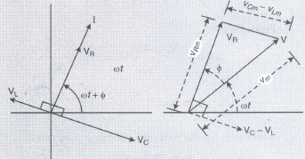
Let VL, VR, Vc and V represent the voltage across the inductor, resistor, capacitor and the source respectively. VR is parallel to I. Vc is pi/2 behind I and VL is pi/2 ahead of I.
Clearly,
\(={ i }_{ 0 }^{ 2 }[{ R }^{ 2 }+({ X }_{ L }-{ X }_{ C })^{ 2 }]\)
\({ i }_{ o }=\frac { { V }_{ 0 } }{ \sqrt { { R }^{ 2 }+({ X }_{ L }-{ X }_{ C })^{ 2 } } } \)
\(Impedence=\frac { { V }_{ 0 } }{ { i }_{ 0 } } =\sqrt { { R }^{ 2 }+({ X }_{ L }-{ X }_{ C })^{ 2 } } \)
\(\\ =\sqrt { { R }^{ 2 }+\left( \omega L-\frac { 1 }{ \omega C } \right) ^{ 2 } } \)
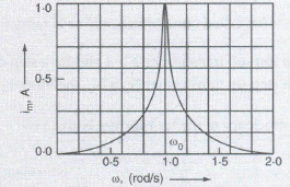
The capacitance of a capacitor in the tuning circuit is varied such that the resonant frequency of the circuit becomes nearly equal to the frequency of the radio signal to be received. When this happens, the amplitude of the current becomes maximum in the receiving circuit.
21.
From Kirchhoff's junction rule, we have
\( { I }_{ 1 }={ I }+{ I }_{ 2 }\) ...........(i)
Applying Kirchhoff's loop rule to outer loop containing 10V cell, we get
\(10=IR+{ 10I }_{ 1 }\) ............(ii)
Applying Kirchhoff's loop rule to outer loop containing 2V cell, we get
\(2={ 5I }_{ 2 }-RI\)
\(2=5\left( { I }_{ 1 }-I \right) -RI\)
\(4={ 10I }_{ 1 }-10I-2RI\)
Subtracting eq (ii) from eq (i), we get
\(6=3RI+10I\)
\(2=I\left( R+\frac { 10 }{ 3 } \right) \)
From Ohm's law, we have
\(V=I\left( R+{ R }_{ off } \right) \)
Comparing eq (iii) and (iv), we get
\({ R }_{ ef }=\frac { 10 }{ 3 } \Omega \)
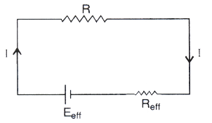
If \({ E }_{ eff }\) and \({ R }_{ eff }\) are the effective voltage and effective internal resistance of the combination, then the equivalent circuit is shown.
22.
(b)
127 µF
23.
(c)
MB (1 - cos θ)
24.
(d)
4960 Ω
25.
(b)
unknown resistance
26.
(b)
one with hole has small magnetic moment
27.
(b)
\(-\vec P.\vec E\)
28.
(b)
R
29.
(c)
Resistor and a capacitor
30.
(b)
anticlockwise
31.
(a)
\(E=-{dV\over dr}\)
32.
(a)
Source charge Q only
33.
(d)
4
34.
(a): According to Faraday's law of electromagnetic induction, induced emf will be generated in the solenoid because of the relative motion between magnet and solenoid.
35.
(c): Consider a conductor of length I and area of cross section A. Time taken by the free electrons to cross the conductor, t = l/vd.
Hence, current, \(I=\frac{q}{t}=\frac{A l \times n e}{l / v_{d}}\)
or, \(I=\text { Anev }_{d}\)
or, \(I \propto v_{d}\)
Thus current is directly proportional to drift velocity.
36.
(c): Earth is a good conductor of very large size. When some small charge is given to earth, its potential does not change. Hence potential of earth is assumed to be zero. It is just like sea level which does not alter materially when water is added to it or removed from it. Thus, the potential of all other bodies are measured with reference to the earth. For this, if the connection of a charged body to the ground by a metallic conductor would cause electrons to flow to that body from ground, the body is at positive potential. Conversely, is also true. In either case the conductor is neutralized and brought to zero potential. In fact the atmosphere does possess significant electric field.
37.
(i) (a) :Magnetic field due to a long current carrying wire at r
\(B=\frac{\mu_{0}}{2 \pi} \frac{I}{r}\)
(ii) (d): Let I' be the current in region r < R
Then, \(I^{\prime}=\frac{I}{\pi R^{2}} \pi\left(r^{2}\right) \text { or } I^{\prime}=\frac{I r^{2}}{R^{2}}\)
So, magnetic. field \(B=\frac{\mu_{0} I^{\prime}}{2 \pi r}=\frac{\mu_{0} I r^{2}}{2 \pi R^{2} r}=\frac{\mu_{0} I r}{2 \pi R^{2}}\)
(iii) (a): Magnetic field due to a long straight wire of radius a carrying current I at a point distant r from the centre of the wire is given as follows
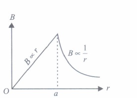
\(B=\frac{\mu_{0} I r}{2 \pi a^{2}} \quad \text { for } \quad r<a\)
\(B=\frac{\mu_{0} I}{2 \pi a} \quad \text { for } r=a\)
\(B=\frac{\mu_{0} I}{2 \pi r} \quad \text { for } r>a\)
The variation of magnetic field B with distance r from the centre of wire is shown in the figure.
(iv) (d): Let the magnetic fields due to a long straight wire of radius R carrying a steady current I at a distance r from the centre of the wire are
\(B_{1}=\frac{\mu_{0} I r}{2 \pi R^{2}} \quad(\text { For } r<R)\)
and \(B_{2}=\frac{\mu_{0} I}{2 \pi R} \quad(\text { For } r>R)\)
So, the magnetic field at \(r=\frac{R}{2} \text { is } B_{1}=\frac{\mu_{0} I}{2 \pi R^{2}}\left(\frac{R}{2}\right)=\frac{\mu_{0} I}{4 \pi R}\)
and at \(r=2 R \text { is } B_{2}=\frac{\mu_{0} I}{2 \pi(2 R)}=\frac{\mu_{0} I}{4 \pi R}\)
\(\therefore\) Their corresponding ratio is \(\frac{B_{1}}{B_{2}}=\frac{\left(\mu_{0} I / 4 \pi R\right)}{\left(\mu_{0} I / 4 \pi R\right)}=1\)
(v) (c)
38.
(I) (b): \((S+x)=\frac{Q}{P} R\)
\(x=\frac{Q}{P} R-S=\frac{6}{5} \times 10-5=7 \Omega\)
(ii) (a): A Wheatstone bridge consisting of four arms of resistance P, Q, R, S is most sensitive when all the resistances are equal.
(iii) (a) : When metal wire is heated, its resistance increases R1 increases,L1 increases.
The null point shift to the right.
(iv) (c): The percentage error in measuring resistance with a metre bridge can be minimized by adjusting the balancing point near the middle of the bridge i.e. close to 50 cm
(v) (c): \(\frac{P}{Q}=\frac{l_{1}}{100-l_{1}} \text { or } \frac{2}{3}=\frac{l_{1}}{100-l_{1}}\)
\(\text { or } \quad 5 l_{1}=200 \text { or } l_{1}=40 \mathrm{~cm}\)

12th Standard CBSE Syllabus & Materials
12th Standard CBSE
CBSE 12th Computer Science Python Revision Tour I - New Previous year Question Papers Study Material - QB365 Set A
NEW12th Standard CBSE
CBSE 12th Business Studies Planning Important Questions And Answers Study Material - QB365 Set A
NEW12th Standard CBSE
CBSE 12th Business Studies Business Environment Important Questions And Answers Study Material - QB365 Set A
NEW12th Standard CBSE
CBSE 12th Business Studies Principles of Management Important Questions And Answers Study Material - QB365 Set A



NCERT Books

Syllabus

Exam Pattern

Sample Question Papers

Previous year Question Papers

Important Notes

MCQ Practice test

NCERT Exemplers

Case study Questions

Image Based Questions

Passage based Questions

HOT Questions

Value Based Questions

Model Questions Papers
NCERT ( Book Back ) Questions

Assertion and Reason
Important Questions And Answers

CBSE 12th Standard CBSE Subjects
CBSE Standards