100% FREE ACCESS
12th Standard CBSE Syllabus & Materials
12th Standard CBSE
CBSE 12th Economics Government Budget and the Economy Previous year Question Papers Study Material - QB365 Set A
NEW12th Standard CBSE
CBSE 12th Computer Science Interface Python with MySQL - New Previous year Question Papers Study Material - QB365 Set A
NEW12th Standard CBSE
CBSE 12th Computer Science Database Concept - New Previous year Question Papers Study Material - QB365 Set A
NEW12th Standard CBSE
CBSE 12th Computer Science Data Communication - New Previous year Question Papers Study Material - QB365 Set A
NEW12th Standard CBSE
CBSE 12th Computer Science Data Structures - New Previous year Question Papers Study Material - QB365 Set A
NEW12th Standard CBSE
CBSE 12th Computer Science Functions - New Previous year Question Papers Study Material - QB365 Set A

Published on: 25/10/2025
Download CBSE Class 12th Standard CBSE Physics question papers, sample papers, important questions, and previous year solved papers in PDF format. Get free study materials, NCERT solutions, and exam preparation resources for Class 12th Standard CBSE Physics
Questions + Answers key
Take MCQ Physics Test
1.
Write three points of differences between para-, dia- and ferro-magnetic materials, giving one example for each.
2.
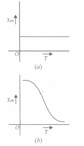
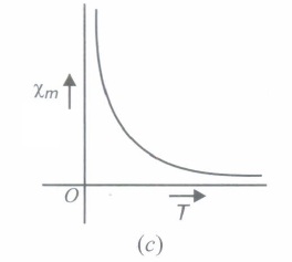
Three curves are shown in the figures. Indicate what magnetic substance they represent.
3.
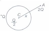
A thin metallic spherical shell of radius R carries a charge Q on its surface. A point charge \(\frac{Q}{2}\) is placed at its centre C and an other charge +2Q is placed outside the shell at a distance x from the centre as shown in figure. Find
(i) the force on the charge at the centre of shell and. at the point A,
(ii) the electric flux through the shell.
4.
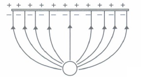
(a) A point charge (+Q) is kept in the vicinity of uncharged conducting plate. Sketch electric field lines between the charge and the plate.
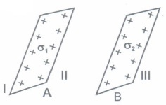
b) Two infinitely large plane thin parallel sheets having surface charge densities \(\sigma_{1} \text { and } \sigma_{2}\left(\sigma_{1}>\sigma_{2}\right)\) are shown in the figure. Write the magnitudes and directions of net fields in the regions marked II and III.
5.
State Gauss' law in electrostatics. Using this law derive an expression for the electric field due to a long straight wire of linear charge density \(\lambda\) C/m.
6.
Using Gauss's law deduce the expression for the electric field due to a uniformly charged spherical conducting shell of radius R at a point (i) outside, and (ii) inside the shell. Plot a graph showing variation of electric field as function of r > R and r < R (r being the distance from the centre of the shell)
7.
Calculate the torque of 100 turns rectangular coil of length 40 cm and breadth 20 cm, carrying a current 10 A , when placed making an angle of \({ 60 }^{ 0 }\) with a magnetic field of 5 T.
8.
Calculate the amount of heat produced per second when a bulb of 100 W, 220 V glows, assuming that only 20% of electric energy is converted into light. J = 4.2 J cal-1.
9.
A coil has 50 turns and its area is.\(500 \ { cm }^{ 2 }\) It is rotating at the rate of 50 r.p.s at right angles to a magnetic field of.\(0.5 \ Wb/{ m }^{ 2 }\) Calculate the maximum value of electromotive force developed across the ends of the coil.
10.
A toroidal solenoid with an air core has an average radius of 15 cm, area of cross-section 12 \({ cm }^{ 2 }\) and 1200 turns. Obtain the self-inductance of the toroid. Ignore field variation across the cross-section of the toroid. A second coil of 300 turns is wound closely on the toroid above. If the current in the primary coil is increased from zero to 2.0 A in 0.05 s, obtain the induced e.m.f. in the second coil.
11.
A solenoid 50 cm long has 4 layers of winding of 350 turns each. The radius of the lowest layer is 1.4 cm. If the current carried is 6.0 A, estimate the magnitude of B
(a) near the centre of the solenoid on its axis, and off its axis.
(b) near its ends on its axis.
(c) outside the solenoid near its centre.
12.
A silver wire has a resistance of 2.1\(\Omega\) at 27.5oC and a resistance of 2.7\(\Omega\) at 100oC. Determine the temperature coefficient of resistivity of silver.
13.
A storage capacitor on a RAM (Random Access Memory) chip has a capacity of 55pF. If the capacitor is charged to 5.3 V, how may excess electrons are on its negative plate?
14.
A magnetic wire of dipole moment 4\(\pi\) A-m2 is bent in the form of semicircle. Find the new magnetic moment.
15.
Consider three charged bodies A , B and C. If A and B repel each other and A attracts C, then what is nature of the force between B and C?
16.
A charge particle moving in a magnetic field penetrates a layer of lead and thereby losses half of its kinetic energy. How does the radius of curvature of its path change?
17.
On what factors does the magnitude of the emf induced in the circuit due to magnetic flux depend?
18.
Two different wires X and Y of the same diameter but different materials are joined in series across a battery. If the number density of electrons in X is twice that in Y, find the ratio of drift velocity of electrons in the two wires.
19.
A current of 10A is flowing from east to west in a long straight wire kept on a horizontal table. The magnetic field developed at a distance of 10 cm due north on the table is
2 x 10⁻⁵ T, acting downwards
2 x 10⁻⁵ T, acting upwards
4 x 10⁻⁵ T, acting downwards
4 x 10⁻⁵ T, acting upwards
20.
A coil having 500 sq. loops of side 10 cm is placed normal to magnetic flux which increases at a rate of 1 T/s. The induced emf is
0.1 V
0.5 V
1V
5V
21.
An electron of charge e moves in a circular orbit of radius r around orbital motion of the electron is
\(\pi \text { ver }^{2}\)
\(\frac{\pi v r^{2}}{e}\)
\(\frac{\pi v e}{r}\)
\(\frac{\pi e r^{2}}{v}\)
22.
Four charges are arranged at the comers of a square ABCD, as shown. The force on the charge kept at the centre O is
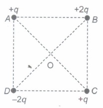
zero
along the diagonal AC
along the diagonal BD
perpendicular to side AB
23.
Two batteries of emf ε1 and ε2, (ε2 >ε1) and internal resistances r1 and r2 respectively are connected in parallel as shown in figure.
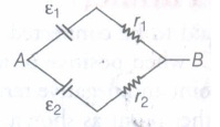
Two equivalent emf εeq of the two cells is between ε1 and ε2 i.e., ε2 < εeq < ε2
The equivalent emf εeq is smaller than ε1
The εeq is given by εeq = ε1 + ε2 always
εeq is independent of internal resistances ε1 and ε2
24.
The resistance of a 10 m long wire is 10Ω. Its length is increased by 25%by stretching the wire uniformly. The resistance of wire will change to
12.5 Ω
14.5 Ω
15.6 Ω
16.6 Ω
25.
The self-inductance of a coil is 2 mH. The rate of flow of current in it is 103 A/S. The induced electromotive force in the coil is
1V
2V
3V
4V
26.
Two equal and opposite charges each of 2C are placed at a distance of 0.04 m. Dipole moment of the system will be
6 x 10⁻⁸ C-m
8 x 10⁻² C-m
1.5 x 10² C-m
8 x 10⁻⁶ C-m
27.
The intensity of magnetic field at a point X on the axis of a small magnet is equal to the field intensity at another point Y on equatorial axis. The ratio of distance of X and Y from the centre of the magnet will be
(2) - 3
(2) - 1/3
2 3
2 1/3
28.
A charge q is placed at the mid point of the line joining two similar and equal charges each equal to + 2μ C. The system will be in equilibrium if q =
-0.5μ C
-1.0μ C
+1.0μ C
+0.5μ C
29.
Quantization of charge Implies:
charge exists on particles
there is a minimum permissible magnitude of charge
charge, which is a fraction of coulomb is not possible
none of the above
30.
A straight wire of mass 200 g and length 1.5 m carries a current of 2 A. It is suspended in mid air by uniform horizontal magnetic field B. The magnitude of B (in Tesla) is : (Take \(g=9.8m/{ s }^{ 2 }\))
2
1.5
0.55
0.65
31.
A 200 \(\mu\)F parallel plate capacitor having plate separation of 5 mm is charged by a 100 V DC Source. It remains connected to the source. Using an insulated handle, the distance between the plates is doubled and a dielectric slab of thickness 5 mm and dielectric constant 10 is introduced between the plates. Explain with reason, how the (i) capacitance, (ii) electric field between the plates and (iii) energy density of the capacitor will change.
32.
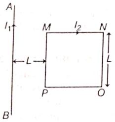
A square shaped current carrying loop MNOP is placed near a straight long current carrying wire AB as shown in the figure. The wire and the loop lie in the same plane. If the loop experiences a net force F towards the wire, find the magnitude of the force on the side NO of the loop.
33.
When 14 cells in series, are connected to the ends of a resistance of 82.6 Ω, then the current is found to be 0.25A. When same cells after being connected in parallel are joined to the ends of a resistance of 0.053 Ω, then the current is 25A. Calculate the internal resistance and the emf of each cell.
34.
Two point charges 4\(\mu\)C and + 1 \(\mu\)C areseparated by a distance of 2 m in air. Find the point on the line joining charges at which the net electric field of the system is zero.
35.
(a) Why does a paramagnetic sample display greater magnetisation (for the same magnetising field) when cooled?
(b) Why is diamagnetism, in contrast, almost independent of temperature?
(c) If a toroid uses bismuth for its core, will the field in the core be (slightly) greater or (slightly) less than when the core is empty?
(d) Is the permeability of a ferromagnetic material independent of the magnetic field? If not, is it more for lower or higher fields?
(e) Magnetic field lines are always nearly normal to the surface of a ferromagnet at every point. (This fact is analogous to the static electric field lines being normal to the surface of a conductor at every point.) Why?
(f ) Would the maximum possible magnetisation of a paramagnetic sample be of the same order of magnitude as the magnetisation of a ferromagnet?
36.
37.
Assertion (A) Diamagnetic substances exhibit magnetism.
Reason (R) Diamagnetic materials do not have permanent magnetic dipole moment.
(a) Both Assertion and Reason are true and Reason is the correct explanation of Assertion.
(b) Both Assertion and Reason are true but Reason is not the correct explanation of Assertion.
(c) Assertion is true but Reason is false.
(d) Assertion is false but Reason is true
38.
Assertion (A) : If a point charge q is placed in front of an infinite grounded conducting plane surface, the point charge will experience a force.
Reason (R) : This force is due to the induced charge on the conducting surface which is at zero potential.
Codes:
(a) Both A and R are true and R is the correct explanation of A
(b) Both A and R are true but R is NOT the correct explanation of A
(c) A is true but R is false
(d) A is false and R is also false
39.
Mutual inductance is the phenomenon of inducing emf in a coil, due to a change of current in the neighbouring coil. The amount of mutual inductance that links one coil to another depends very much on the relative positioning of the two coils, their geometry and relative separation between them. Mutual inductance between the two coils increases \(\mu_{r}\) times if the coils are wound over an iron core of relative permeability \(\mu_{r}\).
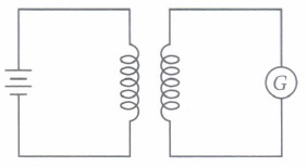
(I) A short solenoid of radius a, number of turns per unit length nI' and length L is kept coaxially inside a very long solenoid of radius b, numbdr of turns per unit length n2• What is the mutual inductance of the system?
| \(\text { (a) } \mu_{0} \pi b^{2} n_{1} n_{2} L\) | \(\text { (b) } \mu_{0} \pi a^{2} n_{1} n_{2} L^{2}\) | \(\text { (c) } \mu_{0} \pi a^{2} n_{1} n_{2} L\) | \(\text { (d) } \mu_{0} \pi b^{2} n_{1} n_{2} L^{2}\) |
(ii) If a change in current of 0.01 A in one coil produces a change in magnetic flux of 2 x l0-2 weber in another coil, then the mutual inductance between coils is
| (a) 0 | (b) 0.5 H | (c) 2 H | (d) 3 H |
(iii) Mutual inductance of two coils can be increased by
| (a) decreasing the number of turns in the coils |
| (b) increasing the number of turns in the coils |
| (c) winding the coils on wooden cores |
| (d) none of these |
(iv) When a sheet of iron is placed in between the two co-axial coils, then the mutual inductance between the coils will
| (a) increase | (b) decrease |
| (c) remains same | (d) cannot be predicted |
(v) The SI unit of mutual inductance is
| (a) ohm | (b) mho | (c) henry | (d) none of these |
40.
When the atomic dipoles are aligned partially or fully, there is a net magnetic moment in the direction of the field in any small volume of the material. The actual magnetic field inside material placed in magnetic field is the sum of the applied magnetic field and the magnetic field due to magnetisation. This field is called magnetic intensity (H).
\(H=\frac{B}{\mu_{0}}-M\)
where M is the magnetisation of the material, llo is the permittivity of vacuum and B is the total magnetic field. The measure that tells us how a magnetic material responds to an external field is given by a dimensionless quantity is appropriately called the magnetic susceptibility: for a certain class of magnetic materials, intensity of magnetisation is directly proportional to the magnetic intensity.
(i) Magnetization of a sample is
| (a) volume of sample per unit magnetic moment | (b) net magnetic moment per unit volume |
| (c) ratio of magnetic moment and pole strength | (d) ratio of pole strength to magnetic moment |
(ii) Identify the wrongly matched quantity and unit pair.
| (a) Pole strength | Am |
| (b) Magnetic susceptibility | dimensionless number |
| (c) Intensity of magnetisation | A m-1 |
| (d) Magnetic permeability | Henry m |
(iii) A bar magnet has length- 3 cm, cross-sectional area 2 cm2 and magnetic moment 3 A m2. The intensity of magnetisation of bar magnet is
| \(\text { (a) } 2 \times 10^{5} \mathrm{~A} / \mathrm{m}\) | \(\text { (b) } 3 \times 10^{5} \mathrm{~A} / \mathrm{m}\) |
| \(\text { (c) } 4 \times 10^{5} \mathrm{~A} / \mathrm{m}\) | \(\text { (d) } 5 \times 10^{5} \mathrm{~A} / \mathrm{m}\) |
(iv) A solenoid has core of a material with relative permeability 500 and its windings carry a current of 1 A. The number of turns of the solenoid is 500 per metre. The magnetization of the material is nearly
| \(\text { (a) } 2.5 \times 10^{3} \mathrm{Am}^{-1}\) | \(\text { (b) } 2.5 \times 10^{5} \mathrm{~A} \mathrm{~m}^{-1}\) |
| \(\text { (c) } 2.0 \times 10^{3} \mathrm{~A} \mathrm{~m}^{-1}\) | \(\text { (d) } 2.0 \times 10^{5} \mathrm{~A} \mathrm{~m}^{-1}\) |
(v) The relative permeability of iron is 6000. Its magnetic susceptibility is
| (a) 5999 | (b) 6001 |
| (c) 6000 x 10-7 | (d) 6000 x 107 |
1.
| Paramagnetic Materials | Diamagnetic Materials | Ferromagnetic materials |
| 1. These are materials in which each individual atom has a not nonzero magnetic moment its own. | 1. These are materials in which the individual atoms possess no net magnetic moment of their own. | 1. These are the materials in which the individual atoms have a net non-zero magnetic moment. |
| 2. Magnetic susceptibility is low and positive. | 2. Magnetic susceptibility is low and negative. | 2. Magnetic susceptibility is high and positive. |
| 3. In presence of nonuniform magnetic field, it weakly attracts and tend to move from weaker parts of field to stronger parts. | 3. In presence of nonuniform magnetic field, it repels and tend to move from stronger parts of field to weaker parts. | 3. In presence of nonuniform magnetic field, it strongly attracts and easily move from weaker part of field to stronger parts. |
| 5. Example: Aluminum. | 5. Example: Copper. | 5. Example: Iron |
2.
The figure (a) indicates a diamagnetic material.
The figure (b) indicates a ferromagnetic material.
The figure (c) indicates a paramagnetic material.
3.
(i) As there is no electric field inside thin charged metallic spherical shell,
the force on the charge \(\frac{Q}{2}\) is zero.
Force on charge 2Q at point A.
\( F =E \times 2 Q=\left(\frac{1}{4 \pi \varepsilon_{0}} \frac{3 Q}{2 x^{2}}\right) \cdot 2 Q \)
\(=\frac{1}{4 \pi \varepsilon_{0}} \frac{3 Q^{2}}{x^{2}}\)
(ii) Electric flux through the shell,
\(\phi_{E}=\frac{Q}{2 \varepsilon_{0}}\)
4.
(a) The lines of force due to a positive charge placed near a metal plate are as shown in the figure.
(b) In the region II between the plates \(\vec{E}_{A} \text { and } \vec{E}_{B}\) are opposite to each other.
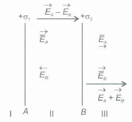
\(\text {As } \sigma_{1}>\sigma_{2},\left|\vec{E}_{A}\right|>\left|\vec{E}_{B}\right|\)
and resultant field \(=E_{A}-E_{B}=\frac{\sigma_{1}}{2 \varepsilon_{0}}-\frac{\sigma_{2}}{2 \varepsilon_{0}}\)
\(\therefore \ \overrightarrow{E_{I I}}=\frac{1}{2 \varepsilon_{0}}\left(\sigma_{1}+\sigma_{2}\right) \text { from } A \text { to } B\)
In the region III, both \(\vec{E}_{A} \text { and } \vec{E}_{B}\) are supporting each other.
∴ \(\overrightarrow{E_{I I I}}=\frac{1}{2 \varepsilon_{0}}\left(\sigma_{1}+\sigma_{2}\right) \text { away from } B .\)
5.
This law gives the relationship between the total flux passing through any closed surface and the net charge enclosed within the surface. Gauss's law states that the total flux through a closed surface is \({{1}\over{{\epsilon}_{0}}}\) times to the net charge enclosed by the closed surface mathematically, \({\phi}_{E}={\phi}_{s}E.dS={{q}\over{{\epsilon}_{0}}}\).
Electric field intensity due to an infinitely long uniformly charged wire at point P at distance r from it is obtained as follows: Consider a thin cylindrical Gaussian surface S with charged wire on its axis and point P on its surface, then net electric flux through surface S is
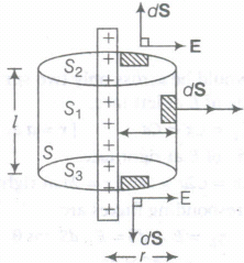
\(\phi=\oint_{s}E.dS=\overset {\int{Eds\ \cos \ 90°} }{ Upper\ plan\ face } + \overset { \int{Eds\ cos\ 90°} }{ Caved\ surface }+\overset { \int{Eds\ cos\ 90°} }{ Lower\ plane\ face }\)
\(\phi\) = 0 + EA + 0 or \(\phi\) = E.2\(\pi rl\)
But by Gauss's theorem,
\(\phi={{q}\over{{\epsilon}_{0}}}={{\lambda \ l}\over{{\epsilon}_{0}}}\)
Where, q is the charge on length l of wire enclosed by cylindrical surface S and \(\lambda\) is uniform linear charge density of wire.
\(\therefore\) \(E\times2\pi r l={{\lambda\ l}\over{{\epsilon}_{0}}}\Rightarrow\ E={{\lambda}\over{3\pi{\epsilon}_{0}r}}\)
Thus, electric field of a line charge is inversely proportional to distance directed normal to the surface of charged wire.
Let us consider a long straight wire carrying + q charge on its length / and linear charge density \(\lambda\) Cm.
\(\therefore\) \(\lambda={{q}\over{l}}\)
\(\Rightarrow\) q = \(\lambda\ l\) ...(i)
Let electric Iiclu intensity is [Q be: obtained .H a distance r from it. Since, magnitude of E due to long charged wire is same at every point which lie at the same distance from the wire. So, Gaussian surface will be a cylinder of radius r and length / such that wire lies along the axis as shown in figure.
\(\because\) Angle between E and dSis 90° at caps, whereas 0° at any point on curved surface of a cylinder. Now, applying Gauss' theorem.
\(\int{E.dS={{q}\over{{\epsilon}_{0}}}}\)
\(\oint_{CSA}E.dS+\oint_{CSA}E.dS={{\lambda\ l}\over{{\epsilon }_{0}}}\) [FromEq. (i)]
[CSA = Close Surface Area]
\(\int_{CSA}E\ dScos\ 90°+\int_{CSA}E\ dS\ cos\ 0°={{\lambda\ l}\over{{\epsilon}_{0}}}\)
(S1 and S3 are caps and S2 represents CSA)
\(0+\int_{CSA}E\ dS={{\lambda l}\over{{\epsilon}_{0}}}\) \([\because\ cos 90°=0]\)
\(E \oint_{CSA}\ dS={{\lambda l}\over{\epsilon_0}}\)
[ \(\because\) E is a constant at every point at CSA]
\(E\times2\pi r l={{\lambda l}\over{{\epsilon}_{0}}}\)
E = \({ {\lambda l }\over{ 2\pi{\epsilon}_{0} r l} }\)
\(\Rightarrow\) E = \({ {\lambda }\over{2\pi{ \epsilon}_{ 0} r} }\)
6.
Electric field due to a uniformly charged thin spherical shell :
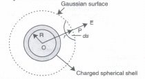
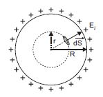
(i) When point P lies outside the spherical shell :Suppose that we have to calculate electric field at the point P at a distance r (r > R) from its centre. Draw the Gaussian surface through point P so as to enclose the charged spherical shell. The Gaussian surface is a spherical shell of radius r and centre O.
Let \(\overrightarrow{E}\) be the electric field at point P, then the electric flux through area element is \(\overrightarrow{ds}\) given by
\(d\phi = \overrightarrow{E}.\overrightarrow{\Delta S}\)
Since \(\Delta\)S is also along normal to the surface,
\(d\phi = E ds\)
\(\therefore\) Total electric flux through the Gaussian surface is given by,
\(\phi = \oint_s Eds = E\oint_s ds\)
Now \(\oint_s ds = 4\pi r^2\)
\(\phi = E \times 4\pi r^2\)................(i)
Since the charge enclosed by the Gaussian surface is q1 according to Gauss theorem,
\(\phi = \frac{q}{\epsilon_0}\) .......................(ii)
From equations (i) and (ii),we obtain
\(E\times4\pi r^2 = \frac{q}{\epsilon_0}\)
\(E = \frac{1}{4\pi\epsilon_0}\frac{q}{r_2}\) ( for ( r > R ) )
(ii) When point P lies inside the spherical shell : In such a case, the Gaussian surface encloses no charge. According to Gauss law,
\(E\times4\pi r^2 = 0\)
i.e., E = 0 (r < R)
Graph showing the variation of electric field as a function of r :
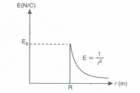
7.
Given, I = 10 A, N = 100, l = 40 cm, b = 20 cm
B = 5 T, \(\theta\)= 60°
A = l \(\times\)b = 40 \(\times\)20 = 800 cm2 = 8 \(\times\)10-2m2
\(\begin{array}{r}
\because \quad \tau=N B I A \sin \theta=100 \times 5 \times 10 \times 8 \times 10^{-2} \times \frac{\sqrt{3}}{2} \\
\end{array}\)
\(\begin{array}{r}
{\left[\because \sin 60^{\circ}=\frac{\sqrt{3}}{2}\right]}
\end{array}\)
= 346.41 N-m
8.
Electric energy consumed per second = 100 J
Heat produced = 80% = \(\frac{80}{100}\times 100\)
= 80 J = \(\frac{80}{4.2}\)
= 19.05 cal
9.
392.8 volt
10.
(a) \(B=\frac { { \mu }_{ 0 }NI }{ 2\pi r } ;\)
\(A=12{ cm }^{ 2 }=12\times { 10 }^{ -4 }{ m }^{ 2 },\)
\(r=15cm=0.15m\)
\(\therefore \) \(\phi =\frac { { \mu }_{ 0 }NI }{ 2\pi r } A,\)
Total flux \(N\phi =\frac { { \mu }_{ 0 }A{ N }^{ 2 } }{ 2\pi r } I\)
Since \(\phi =LI\)
\(\therefore \) \(L=\frac { { \mu }_{ 0 }A{ N }^{ 2 } }{ 2\pi r } \)
\(=\frac { 4\pi \times { 10 }^{ -7 }\times 12\times { 10 }^{ -4 }\times { \left( 1200 \right) }^{ 2 } }{ 2\pi \times 0.05 } \)
\(=2.3mH\)
\(\left| e \right| =\frac { d }{ dt } \left( { N }_{ 2 }{ \phi }_{ 2 } \right) \)
\(={ N }_{ 2 }\frac { { \mu }_{ 0 }{ N }_{ 1 }A }{ 2\pi r } \frac { d{ I }_{ 1 } }{ dt } \)
\(=\frac { 4\pi \times { 10 }^{ -7 }\times 300\times 1200\times 12\times { 10 }^{ -4 }\times 2 }{ 2\pi \times 0.15\times 0.05 } \)
\(\left| e \right| =0.023 \ V\)
11.
The ratio of length to radius of the solenoid is quite large (about 35). Therefore, to estimate B approximately, we can use the exact result for a closely wound infinitely long solenoid.
(a) At the centre or near it,
\(B={ \mu }_{ 0 }nI\)
Where n is the number of turns per unit length.
Note 1. the radius of the wire does not enter this equation. Therefore, to get n, simply multiply number of turns per layer and divide the product by the length of the solenoid.
\(n=\frac { 350\times 4 }{ 0.50 } =2800{ m }^{ -1 }\)
Now \(I=6.0A,\)
and \({ \mu }_{ 0 }=4\pi \times { 10 }^{ -7 }T{ mA }^{ -1 },\)
Which gives \(B=2.1\times { 10 }^{ -2 }T\)
Note 2. This estimate of B is for both on and off the axis, since for an infinitely long solenoid, the internal field near the centre is uniform over the entire cross-section.
(b) At the end of the solenoid,
\(B=\frac { { \mu }_{ 0 }nI }{ 2 }\)
\(=1.05\times { 10 }^{ -2 }T\)
(c) The outside field near the centre of long solenoid is negligible to the internal field.
12.
Temperature, T1 = 27.5°C
Resistance of the silver wire at T1, R1 = 2.1 Ω
Temperature, T2 = 100°C
Resistance of the silver wire at T2, R2 = 2.7 Ω
Temperature coefficient of silver = α
It is related with temperature and resistance as
\(\alpha=\frac{R_{2}-R_{1}}{R_{2}\left(T_{2}-T_{1}\right)}\)
\(=\frac{2.7-2.1}{2.1(100-27.5)}=0.0039^{\circ} \mathrm{C}^{-1}\)
Therefore, the temperature coefficient of silver is 0.0039°C−1.
13.
Given: \(C=55 \times 10^{-12} \mathrm{~F}, V=5.3 \mathrm{~V}\)
\( \because \ Q =C V=n e \)
\(\therefore n=\frac{55 \times 10^{-12} \times 5.3}{1.6 \times 10^{-19}}=1.8 \times 10^{9} \text { electrons } \)
14.
If length of wire is 2l , then magnetic moment
M = m x 2l = 4\(\pi\) A-m2 [given]
As wire is bent in the form of semicircle, effective distance between the ends is 2r.
So, new dipole moment
\(M^{\prime}=m \times 2 r=m \times 2 \times \frac{2 l}{\pi}=\frac{2}{\pi}(m \times 2 l) \quad[\because \pi r=2 l]\)
\(=\frac{2}{\pi} M=\frac{2}{\pi} 4 \pi\)
= 8 A - m2
15.
It is also attractive in nature.
16.
r = mv/qB .........(i)
Also P = mv = \(\sqrt { 2mE } \)..........(ii)
By equ (i) and equ (ii)
As the radius is \(r\frac { \sqrt { 2mE } }{ qB } \) proportional to square root of kinetic energy, so if the kinetic energy is halved the radius become \(\sqrt { 1 } /2\) times of its initial value
17.
The magnitude of the emf induced in the circuit due to magnetic flux depends on the time rate of change of magnetic flux through the circuit.
\(|\varepsilon|=\frac{\Delta \phi}{\Delta t}\)
18.
Drift velocity,
Since the wires are connected in series, current I through both is same. Therefore,
19.
(a)
2 x 10⁻⁵ T, acting downwards
20.
(d)
5V
21.
(a)
\(\pi \text { ver }^{2}\)
22.
(c)
along the diagonal BD
23.
(a)
Two equivalent emf εeq of the two cells is between ε1 and ε2 i.e., ε2 < εeq < ε2
24.
(c)
15.6 Ω
25.
(b)
2V
26.
(b)
8 x 10⁻² C-m
27.
(d)
2 1/3
28.
(a)
-0.5μ C
29.
(b)
there is a minimum permissible magnitude of charge
30.
(b)
1.5
31.
Given, C = 200 \(\mu\)F, d = 5 mm, t = 5 mm, V = 100 V
\(\text { (i) } C=\frac{\varepsilon_0 A}{d} \Rightarrow A=\frac{C d}{\varepsilon_0}\)
\(A=\frac{200 \times 10^{-6} \times 5 \times 10^{-3}}{8.85 \times 10^{-12}}=112.99 \times 10^3 \mathrm{~m}^2\)
When d' = 2d, then C' = \(\frac{\varepsilon_0 A}{2 d-t+\frac{t}{K}}\)
\(=\frac{8.85 \times 10^{-12} \times 112.99 \times 10^3}{\left(10-5+\frac{5}{10}\right) \times 10^{-3}}\)
\(=181.8 \times 10^{-6}=181.8 \mu \mathrm{F}\)
(i) Charge on capacitor, q = C0V0
= 200 \(\times\) 10-6 \(\times\) 100
= 2 \(\times\) 10-2 C
\(\begin{aligned}
\Rightarrow \quad C_0 V_0 & =C^{\prime} V^{\prime}
\end{aligned}\)
\(\begin{aligned}
\text { or } \quad V^{\prime} & =\frac{C_0 V_0}{C^{\prime}}=\frac{2 \times 10^{-2}}{181.8 \times 10^{-6}}=110 \mathrm{~V}
\end{aligned}\)
\(\begin{aligned}
E_0 & =\frac{V_0}{d}=\frac{100}{5 \times 10^{-3}}=20 \times 10^3 \mathrm{~V} / \mathrm{m} \\
\end{aligned}\)
\(\begin{aligned}
E^{\prime} & =\frac{V^{\prime}}{2 d}=\frac{110}{10 \times 10^{-3}}=11 \times 10^3 \mathrm{~V} / \mathrm{m}
\end{aligned}\)
(iii) \(\begin{gathered}
\bar{U}=\frac{1}{2} \varepsilon_0 E_0^2=\frac{1}{2} \times 8.85 \times 10^{-12} \times\left(20 \times 10^3\right)^2 \\
\end{gathered}\)
\(\begin{aligned}
=1770 \times 10^{-6} \mathrm{~J} / \mathrm{m}^3
\end{aligned}\)
\(\begin{aligned}
(\bar{U})^{\prime} & =\frac{1}{2} \times \varepsilon_0\left(E^{\prime}\right)^2 \\
\end{aligned}\)
\(\begin{aligned}
& =\frac{1}{2} \times 8.85 \times 10^{-12} \times\left(11 \times 10^3\right)^2 \\
\end{aligned}\)
\(\begin{aligned}
=535.42 \times 10^{-6} \mathrm{~J} / \mathrm{m}^3
\end{aligned}\)
32.
The given loop can be shown below as
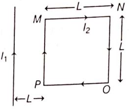
The force acting on the arms MN and PO of the given loop are equal, mutually opposite and collinear, hence they balance each other.
Force on arm PM,
\(F_1=\frac{\mu_0 I_1 I_2 L}{2 \pi L}=\frac{\mu_0 I_1 I_2}{2 \pi}\), attractive in nature ...(i)
Force on arm NO,
\(F_2=\frac{\mu_0 I_1 I_2 L}{2 \pi(2 L)}=\frac{\mu_0 I_1 I_2}{4 \pi},\) , repulsive in nature ...(ii)
From Eqs. (i) and (ii), we get
F = F = F1 - F2
\(=\frac{\mu_0 I_1 I_2}{2 \pi}-\frac{\mu_0 I_1 I_2}{4 \pi}\)
\(=\frac{\mu_0 I_1 I_2}{4 \pi}\)attractive in nature ...(iii)
So, from Eqs. (ii) and (iii), we can conclude that the magnitude of the force on side NO of the loop is \(F=\left(\frac{\mu_0 I_1 I_2}{4 \pi}\right)\) when the net force F is towards the wire.
33.
Let E and r be the emf and internal resistance of each cell.
Case I When the cells are in series.
Total emf of cells = 14E
Total resistance of circuit = 82.6 + 14r
∴ Current in the circuit is given by
\(\frac{14 E}{82.6+14 r}=0.25 \mathrm{~A}\)
Case II When the cells are in parallel.
Total emf of cells = E
Total resistance of circuit = 0.053 \(+\frac{r}{14}\)
∴ Current in the circuit is given by
\(\frac{E}{0.053+\frac{r}{14}}=25 \mathrm{~A}\)
Dividing Eq. (i) by Eq. (ii), we get
\(14 \frac{\left(0.053+\frac{r}{14}\right)}{(82.6+14 r)}=10^{-2}\)
\(\Rightarrow \ 14 \times \frac{14 \times 0.053+r}{14} \times 10^{2}=82.6+14 r\)
⇒ 53 x 14 + 100r = 82.6 + 14r
Solving, we get
r = 0.097Ω ≈ 0.1 Ω
Substituting the value of r in Eq. (i), we get
E = 1.5V
34.
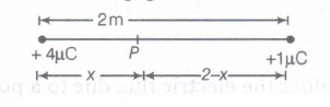
Let the net electric field be zero at point P at a distance x from charge +4\(\mu\)C, then
\(\frac{1}{4 \pi \varepsilon_{0}} \frac{4 \times 10^{-6}}{x^{2}}-\frac{1 \times 10^{-6} \times 1}{4 \pi \varepsilon_{0} \times(2-x)^{2}}=0\)
\(\Rightarrow \ \frac{4}{x^{2}}=\frac{1}{(2-x)^{2}}\)
\(\Rightarrow \ \frac{2}{x}=\frac{1}{2-x}\)
\(\Rightarrow\) x = 4-2x
\(\Rightarrow \ x=\frac{4}{3} \mathrm{~m}\)
35.
(a) Owing to therandom thermal motion of molecules, the alignments of dipoles get disrupted at high temperatures. On cooling, this disruption is reduced. Hence, a paramagnetic sample displays greater magnetisation when cooled.
(b) The induced dipole moment in a diamagnetic substance is always opposite to the magnetising field. Hence, the internal motion of the atoms (which is related to the temperature) does not affect the diamagnetism of a material.
(c) Bismuth is a diamagnetic substance. Hence, a toroid with a bismuth core has a magnetic field slightly greater than a toroid whose core is empty.
(d)The permeability of ferromagnetic materials is not independent of the applied magnetic field. It is greater for a lower field and vice versa.
(e)The permeability of a ferromagnetic material is not less than one. It is always greater than one. Hence, magnetic field lines are always nearly normal to the surface of such materials at every point.
(f)The maximum possible magnetisation of a paramagnetic sample can be of the same order of magnitude as the magnetisation of a ferromagnet. This requires high magnetising fields for saturation.
36.
37.
(a) Both Assertion and Reason are true and Reason is the correct explanation of Assertion.
38.
(a) (a) Both A and R are true and R is the correct explanation of A
39.
(i) (c) :The mutual inductance ofthe system is \(M=\mu_{0} n_{1} n_{2} \pi a^{2} L\)
(ii) (c): Here \(\phi_{B}=2 \times 10^{-2} \mathrm{~Wb}, I=0.01 \mathrm{~A}\)
As \(\phi_{B}=M I\)
\(\therefore\) Mutual inductance between two coils is \(M=\frac{\phi_{B}}{I}=\frac{2 \times 10^{-2} \mathrm{~Wb}}{0.01 \mathrm{~A}}=2 \mathrm{H}\)
(iii) (b) : Mutual inductance of coils \(M=\frac{\mu_{0} \mu_{r} N_{1} N_{2} A}{l}\)
It is clear that mutual inductance of coils can be increased by increasing the number of turns in the coils.
(iv) (a) : We know that the mutual inductance depends (directly proportional) on the permeability of the medium surrounding the coils. When the permeability of the medium is increased by inserting a sheet of iron, then the mutual inductance between the coils also increases.
(v) (c)
40.
(i) (b)
(ii) (d): Magnetic permeability - Henry m-1
(iii) (d): Given, L= 3 cm, A = 2 cm2, M = 3 A m2
.Intensity of magnetisation \(=\frac{M}{l A}=\frac{3}{3 \times 10^{-2} \times 2 \times 10^{-4}}\)
\(=\frac{1}{2 \times 10^{-6}}=0.5 \times 10^{6}=5 \times 10^{5} \mathrm{~A} / \mathrm{m}\)
(iv) (b): Here, n = 500 turns/m
\(I=1 \mathrm{~A}, \mu_{-}=500\)
Magnetic intensity \(H=n I=500 \mathrm{~m}^{-1} \times 1 \mathrm{~A}=500 \mathrm{~A} \mathrm{~m}^{-1}\)
As \(\mu_{r}=1+\chi \quad \text { or } \chi=\left(\mu_{r}-1\right)\)
Magnetisation, M = XH
\(=\left(\mu_{r}-1\right) H=(500-1) \times 500 \mathrm{~A} \mathrm{~m}^{-1}\)
\(=2.495 \times 10^{5} \mathrm{~A} \mathrm{~m}^{-1} \approx 2.5 \times 10^{5} \mathrm{~A} \mathrm{~m}^{-1}\)
(v) (a): Relative permeability of iron \(\mu_{r}=6000\)
Magnetic susceptibility \(\chi_{m}=\mu_{r}-1=5999\)

12th Standard CBSE Syllabus & Materials
12th Standard CBSE
CBSE 12th Computer Science Python Revision Tour I - New Previous year Question Papers Study Material - QB365 Set A
NEW12th Standard CBSE
CBSE 12th Business Studies Planning Important Questions And Answers Study Material - QB365 Set A
NEW12th Standard CBSE
CBSE 12th Business Studies Business Environment Important Questions And Answers Study Material - QB365 Set A
NEW12th Standard CBSE
CBSE 12th Business Studies Principles of Management Important Questions And Answers Study Material - QB365 Set A



NCERT Books

Syllabus

Exam Pattern

Sample Question Papers

Previous year Question Papers

Important Notes

MCQ Practice test

NCERT Exemplers

Case study Questions

Image Based Questions

Passage based Questions

HOT Questions

Value Based Questions

Model Questions Papers
NCERT ( Book Back ) Questions

Assertion and Reason
Important Questions And Answers

CBSE 12th Standard CBSE Subjects
CBSE Standards