100% FREE ACCESS
12th Standard CBSE Syllabus & Materials
12th Standard CBSE
CBSE 12th Economics Government Budget and the Economy Previous year Question Papers Study Material - QB365 Set A
NEW12th Standard CBSE
CBSE 12th Computer Science Interface Python with MySQL - New Previous year Question Papers Study Material - QB365 Set A
NEW12th Standard CBSE
CBSE 12th Computer Science Database Concept - New Previous year Question Papers Study Material - QB365 Set A
NEW12th Standard CBSE
CBSE 12th Computer Science Data Communication - New Previous year Question Papers Study Material - QB365 Set A
NEW12th Standard CBSE
CBSE 12th Computer Science Data Structures - New Previous year Question Papers Study Material - QB365 Set A
NEW12th Standard CBSE
CBSE 12th Computer Science Functions - New Previous year Question Papers Study Material - QB365 Set A

Published on: 25/10/2025
Download CBSE Class 12th Standard CBSE Physics question papers, sample papers, important questions, and previous year solved papers in PDF format. Get free study materials, NCERT solutions, and exam preparation resources for Class 12th Standard CBSE Physics
Questions + Answers key
Take MCQ Physics Test
1.
Write three points of differences between para-, dia- and ferro-magnetic materials, giving one example for each.
2.
You are given three circuit elements X, Y and Z. When the element X is connected across an ac source of a given voltage, the current and the voltage are in the same phase. When the element Y is connected in series with X across the source, voltage is ahead of the current in phase by π/4. But the current is ahead of the voltage in phase by π/4 when Z is connected in series with X across the source. Identify the circuit elements X, Y and Z.
When all the three elements are connected in series across the same source, determine the impedance of the circuit.
Draw a plot of the current versus the frequency of applied source and mention the significance of this plot.
3.
A rectangular loop of wire of size 4 cm x 10 cm carries a steady current of 2 A. A straight long wire carrying 5 A current is kept near the loop as shown. If the loop and the wire are coplanar, find
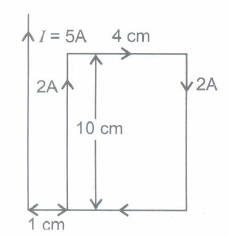
(i) the torque acting on the loop and
(ii) the magnitude and direction of the force on the loop due to the current carrying wire.
4.
Derive the expression for the torque \(\tau \) acting on a rectangular current loop of area A placed in a uniform magnetic field B. Show that \(\overrightarrow { \tau } =\overrightarrow { m } \times \overrightarrow { B } \) where \(\overrightarrow { m } \) is the magnetic moment of the current loop given by \(\overrightarrow { m } =I\overrightarrow { A } \)
5.
In a galvanometer there is a deflection of 10 divisions per mA. The internal resistance of the galvanometer is 60 \(\Omega \) . If a shunt of 2.5 \(\Omega \) is connected to the galvanometer and there are 50 divisions in all on the scale of galvanometer what maximum current can this galvanometer read ?
6.
The magnetic flux through a coil perpendicular to its plane is varying according to the relation \(\phi =\left( 5{ t }^{ 3 }+4{ t }^{ 2 }+2t-5 \right) Wb\). Calculate the induced current through the coil at t = 2s, if the resistance of the coil is \(10\Omega .\)
7.
A bar magnet of magnetic moment 1.5 JT-1 lies aligned with the direction of a uniform magnetic field of 0.22T.
(a) What is the amount of work required by an external torque to turn the magnet so as to align its magnetic moment,
(i) normal to the field direction
(ii) opposite to the field direction.
(b) What is the torque on the magnet in cases (i) and (ii)?
8.
(i) The graph (a) and (b) represent the variation of the opposition offered by the circuit element to the flow of alternating current with frequency of the applied emf. Identify the circuit elements corresponding to each graph.
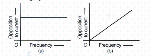
(ii) Write the expression for the impedance offered by the series combination of the above two elements connected across the AC source. Which will be ahead in phase in this circuit, voltage or current?
9.
Two long parallel wires carrying a current I, separated by a distance r are exerting a force F on each other. If the distance between them is increased to 2r and current in each wire is reduced from I to I / 2, then what will be the force between them?
10.
A conductor of length 2 m carrying current of 2 A is held parallel to an infinitely long conductor carrying current of 10 A at a distance of 100 mm. Find the force on a small conductor?
11.
Using the concept of force between two infinitely long parallel current carrying conductors, define one ampere of current.
12.
A circular loop of radius 0.2 m carrying a current of 1 A is placed in a uniform magnetic field of 0.5 T. The magnetic field is perpendicular to the plane of the loop. What is the force experienced by the loop ?
13.
An electrical element X when connected to an alternating voltage source has current through it leading the voltage by \(\pi /2\) radian. Identify X and write an expression for its reactance.
14.
In which orientation is the force experienced by a current-carrying conductor placed in a magnetic field (i) minimum (ii) maximum ?
15.
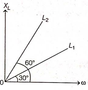
Figure shows the variation of inductive reactance XL,of two ideal inductors of inductances L1 and L2, with angular frequency \(\omega\) The value of \(\frac{L_1}{L_2}\)is
\(\sqrt{3}\)
\(\frac{1}{\sqrt{3}}\)
3
\(\frac{1}{3}\)
16.
In an a.c. generator, a coil with N turns, all of the same area A and total resistance R, rotates with frequency ω in a magnetic field B the maximum value of emf generated in the coil is
NABR
NABω
NABRω
NAB
17.
If M is magnetic moment and B is magnetic field intensity, then the torque is given by
\(\overline{\mathbf{M}} \cdot \overline{\mathbf{B}}\)
\(\frac{|\overline{\mathbf{M}}|}{|\overline{\mathbf{B}}|}\)
\(\overline{\mathbf{M}} \times \overline{\mathbf{B}}\)
MB
18.
The strength of magnetic field at the centre of circular coil is
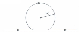
\(\frac{\mu_{0} I}{R}\left(1-\frac{1}{\pi}\right)\)
\(\frac{\mu_{0} \boldsymbol{I}}{\pi \boldsymbol{R}}\)
\(\frac{\mu_{0} I}{2 R}\left(1-\frac{1}{\pi}\right)\)
\(\frac{\mu_{0} I}{2 R}\left(1+\frac{1}{\pi}\right)\)
19.
In a purely inductive AC circuit, L = 30.0 mH and the rms voltage is 150 V, frequency v = 50 Hz. The inductive reactance is
15.9 \(\Omega\)
9.42 \(\Omega\)
10 \(\Omega\)
8.85 \(\Omega\)
20.
A 15.0 \(\mu\)F capacitor is connected to a 220 V,50 Hz source. The capacitive reactance is
220 \(\Omega\)
215 \(\Omega\)
212 \(\Omega\)
204 \(\Omega\)
21.
Current in the coil is larger
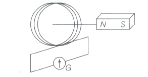
when the magnet is pushed towards the coil faster
when the magnet is pulled away the coil faster
Both (a) and (b)
Neither (a) nor (b)
22.
Cutting a bar magnet in half is like cutting a solenoid, such that we get two smaller solenoids with
weaker magnetic properties
strong magnetic properties
constant magnetic properties
Both (a) and (b)
23.
A charged particle goes undeflected in a region containing electric and magnetic field. It is possible that
\(\vec { E } \parallel \vec { B } \) but \(\vec { \upsilon } \) is not parallel to \(\vec { E } \)
\(\vec { \upsilon } \parallel \vec { B } \) but \(\vec { E } \) is not parallel to \(\vec { B } \)
\(\vec { E } \parallel \vec { B } \), \(\vec { \upsilon } \parallel \vec { E } \)
\(\vec { E } \) is not parallel to \(\vec { B } \) and \(\vec { \upsilon } \)
24.
Two similar coils of radius R, are lying concentrically with their planes at right angles to each other. The currents flowing in them are I and 2 I respectively. The resultant magnetic field at the centre will be :
\(\frac { \sqrt { 5 } { \mu }_{ 0 }I }{ 2R } \)
\(\frac { 3{ \mu }_{ 0 }I }{ 2R } \)
\(\frac { { \mu }_{ 0 }I }{ 2R } \)
\(\frac { { \mu }_{ 0 }I }{ R } \)
25.
A coil of wire has an area of 600 sq. cm and has 500 turns. If it carries 1.5 A current, its magnetic dipole moment is
5 Am2
15 Am2
30 Am2
45 Am2
26.
A circular coil of n turns and radius r carries a current I. The magnetic field at the centre is
\(\frac { { \mu }_{ o }nI }{ r } \)
\(\frac { { \mu }_{ o }nI }{ 2r } \)
\(\frac { { 2\mu }_{ o }nI }{ r } \)
\(\frac { { \mu }_{ o }nI }{ 4r } \)
27.
(i) Write the principle and explain the working of a moving coil galvanometer. A galvanometer as such cannot be used to measure the current in a circuit. Why?
(ii) Why is the magnetic field made radial in a moving coil galvanometer? How is it achieved?
28.
Figure shows a rectangular conducting loop PQRS in which arm RS of length I is movable. The loop is kept in a uniform magnetic field B directed downward perpendicular to the plane of the loop. The arm RS is moved with a uniform speed v.

Deduce the expression for
(i) the emf induced across the arm RS
(ii) the external force required to move the arm and
(ill) the power dissipated as heat.
29.
(i) Using Biot-Savart's law, deduce an expression for the magnetic field on the axis of a circular current carrying loop.
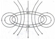
(ii) Draw the magnetic field lines due to a current carrying loop.
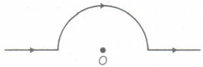
(iii) A straight wire carrying a current of 12 A is bent into a semi-circular arc of radius 2.0 cm as shown in the figure. What is the magnetic field B at 0 due to
(a) straight segments,
(b) the semi-circular arc?
30.
(i) With the help of a labelled diagram, describe briefly the underlying principle and working of a step up transformer.
(ii) Write any two sources of energy loss in a transformer.
(iii) A step up transformer converts a low input voltage in to a high output voltage. Does it violate law of conservartion of energy? Explain.
31.
A series LCR circuit is connected to an ac source having voltage V = Vm sin cot. Derive the expression for the instantaneous current I and its phase relationship to the applied voltage.
Obtain the condition for resonance to occur. Define 'power factor'. State the conditions under which it is (i) maximum and (ii) minimum.
32.
A metallic rod of length l and resistance R is rotated with a frequency v, with one end hinged at the centre and the other end at the circumference of a circular metallic ring of radius l, about an axis passing through the centre and perpendicular to the plane of the ring. A constant and uniform magnetic field B parallel to the axis is present everywhere.
(a) Derive the expression for the induced emf and the current in the rod.
(b) Due to the presence of the current in the rod and of the magnetic field, find the expression for the magnitude and direction of the force acting on this rod.
(c) Hence obtain the expression for the power required to rotate the rod.
33.
34.
Assertion (A) Diamagnetic substances exhibit magnetism.
Reason (R) Diamagnetic materials do not have permanent magnetic dipole moment.
(a) Both Assertion and Reason are true and Reason is the correct explanation of Assertion.
(b) Both Assertion and Reason are true but Reason is not the correct explanation of Assertion.
(c) Assertion is true but Reason is false.
(d) Assertion is false but Reason is true
35.
Assertion (A) : Acceleration of a magnet falling through a copper ring decreases.
Reason (R) : The induced current produced in a circuit always flow in such direction that it opposes the change or the cause that produced it.
Codes:
(a) Both A and R are true and R is the correct explanation of A
(b) Both A and R are true but R is NOT the correct explanation of A
(c) A is true but R is false
(d) A is false and R is also false
36.
When the frequency of ac supply is such that the inductive reactance and capacitive reactance become equal, the impedance of the series LCR circuit i equal to the ohmic resistance in the circuit. Such a series LCR circuit is known as resonant series LCR circuit and the frequency of the ac supply is known as resonant frequency
Resonance phenomenon is exhibited by a circuit only ifboth Land C are present in the circuit. We cannot have resonance in a RL or RC circuit
A series LCR circuit with \(L=0.12 \mathrm{H}, C=480 \mathrm{nF}, R=23 \Omega\) is connected to a 230 V variable frequency supply
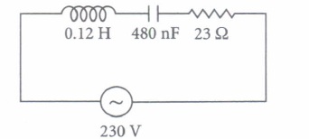
(i) Find the value of source frequency for which current amplitude is maximum
| (a) 222.32 Hz | (b) 550.52 Hz | (c) 663.48 Hz | (d) 770 Hz |
(ii) The value of maximum current is
| (a) 14.14 A | (b) 22.52 A | (c) 50.25 A | (d) 47.41 A |
(iii) The value of maximum power is
| (a) 2200 W | (b) 2299.3 W | (c) 5500 W | (d) 4700 W |
(iv) What is the Q-factor of the given circuit?
| (a) 25 | (b) 42.21 | (c) 35.42 | (d) 21.74 |
(v) At resonance which of the following physical quantity is maximum?
| (a) Impedance | (b) Current | (c) Both (a) and (b) | (d) Neither (a) nor (b) |
37.
Let a source of alternating e.m.f. E = Eosinrot be connected to a capacitor of capacitance C. If 'I' is the instantaneous value of current in the circuit at instant t, then \(I=\frac{E_{0}}{1 / \omega C} \sin \left(\omega t+\frac{\pi}{2}\right)\) The capacitive reactance limits the amplitude of current in a purely capacitive circuit and it is given by \(X_{C}=\frac{1}{\omega C}\)
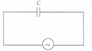
(i) What is the unit of capacitive reactance?
| (a) farad | (b) ampere | (c) ohm | (d) ohm -1 |
(ii) The capacitive reactance of a \(5 \mu \mathrm{F}\) lFcapacitor for a frequency of 106 Hz is
| \(\text { (a) } 0.032 \Omega\) | \(\text { (b) } 2.52 \Omega\) | \(\text { (c) } 1.25 \Omega\) | \(\text { (d) } 4.51 \Omega\) |
(iii) In a capacitive circuit, resistance to the flow of current is offered by
| (a) resistor | (b) capacitor | (c) inductor | (d) frequency |
(iv) In a capacitive circuit, by what value of phase angle does alternating current leads the e.m.f?
| (a) 45° | (b) 90° | (c) 75° | (d) 60° |
(v) One microfarad capacitor is joined to a 200 V, 50 Hz alternator. The rms current through capacitor is
| \(\text { (a) } 6.28 \times 10^{-2} \mathrm{~A}\) | \(\text { (b) } 7.5 \times 10^{-4} \mathrm{~A}\) | \(\text { (c) } 10.52 \times 10^{-2} \mathrm{~A}\) | \(\text { (d) } 15.25 \times 10^{-2} \mathrm{~A}\) |
1.
| Paramagnetic Materials | Diamagnetic Materials | Ferromagnetic materials |
| 1. These are materials in which each individual atom has a not nonzero magnetic moment its own. | 1. These are materials in which the individual atoms possess no net magnetic moment of their own. | 1. These are the materials in which the individual atoms have a net non-zero magnetic moment. |
| 2. Magnetic susceptibility is low and positive. | 2. Magnetic susceptibility is low and negative. | 2. Magnetic susceptibility is high and positive. |
| 3. In presence of nonuniform magnetic field, it weakly attracts and tend to move from weaker parts of field to stronger parts. | 3. In presence of nonuniform magnetic field, it repels and tend to move from stronger parts of field to weaker parts. | 3. In presence of nonuniform magnetic field, it strongly attracts and easily move from weaker part of field to stronger parts. |
| 5. Example: Aluminum. | 5. Example: Copper. | 5. Example: Iron |
2.
X is resistor, because current and voltage are in phase.
Y is inductor, because voltage is ahead of current in phase Z is capacitor, because current is ahead of voltage in phase.
When all the three elements are connected in series, the phasor diagram is as shown below
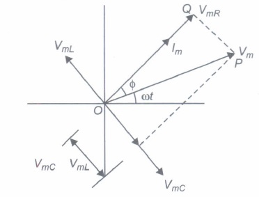
We assume that circuit is capacitive in nature from the impedance triangle OQP, we get
\( V_{m}^{2} =V_{m R}^{2}+\left(V_{m C}-V_{m L}\right)^{2} \)
\(\text {where } V_{m R} =I_{m} R ; V_{m C}=I_{m} X_{C} \text { and } \)
\(V_{m L} =I_{m} X_{L} \)
\( \therefore V_{m} =I_{m} \sqrt{R^{2}+\left(X_{C}-X_{L}\right)^{2}} \)
\(\frac{V_{m}}{I_{m}} =\sqrt{R^{2}+\left(X_{C}-X_{L}\right)^{2}} \)
The impedance of the circuit is given by
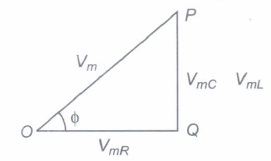
\(Z=\sqrt{R^{2}+\left(X_{C}-X_{L}\right)^{2}}\)
From the graph we come to know about the quality factor of the circuit, i.e. its selectivity.
3.
(i) Torque acting on the loop is given by
\(\tau=M B \sin \theta\)
As the angle between the magnetic field vector and the dipole moment vector is zero.
\(\tau=M B \sin (0)=0 \mathrm{Nm}\)
(ii) Magnitude of force is given by
\(F=\frac{2 \mu_{0} I_{1} I_{2} l}{4 \pi}\left[\frac{1}{r_{1}}-\frac{1}{r_{2}}\right]\)
where \( l=10 \times 10^{-2} \mathrm{~m}, I_{1}=2 \mathrm{~A}, I_{2}=5 \mathrm{~A}
r_{1}=1 \times 10^{-2} \mathrm{~m}, r_{2}=5 \times 10^{-2} \mathrm{~m}
\)
\(F=\left[2 \times 10^{-7} \times 2 \times 5 \times 10^{-1}\right]
\quad\left[\frac{1}{10^{-2}}-\frac{1}{5 \times 10^{-2}}\right]
\)
\(
F =20 \times 10^{-8}\left[1-\frac{1}{5}\right] \times \frac{1}{10^{-2}}
\)
\(=\frac{20 \times 10^{-6} \times 4}{5}=16 \times 10^{-6} \mathrm{~N}\)
The net force is attractive because the arm of the loop carrying current in the same direction as the Direction of current in the wire is nearer.
4.
The force, on a wire of length I,carrying a current I, in a magneticfield \(\overrightarrow { B } \) is given by \(\overrightarrow { F } =\left( \overrightarrow { l } \times \overrightarrow { B } \right) \) For a rectangular loop, places as shown, in a magnetic field \(\overrightarrow { B } \)
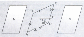
|Force on arm BCI = IForce on arm DAI = l/Bsin \(\alpha\)
Where \(\alpha\)=angle between side BC and \(\overrightarrow { B } \)
These two forces add up to zero as they are collinear (along the axis of the coil) and act in opposite directions
|Force on arm ABI = IForce on arm CDI = IbB
These two equal and opposite forces are not collinear. The perpendicular distance between their lines of action is, as shown
\(2\times\frac{a}{2}sin\theta=a sin\theta\)
Torque acting on the coil, has a magnitude \(\tau \) where
\(\tau \)=(lbB)x(a sin \(\theta\))=IAB sin \(\theta\) (A=ab=Area of the coil)
In vector form, \(\overrightarrow { \tau } =\overrightarrow { A } \times \overrightarrow { B } \)
But \(I\overrightarrow { A } \)=\(\overrightarrow { m } \), as given
\(\overrightarrow { \tau } =\overrightarrow { m } \times \overrightarrow { B } \)
5.
Since the galvanometer has 50 divisions, so current for full scale deflection is
\({ I }_{ g }=\frac { 1 }{ 10 } \times 50 \ mA=5mA=5\times { 10 }^{ -3 }A,\)
\(G=60\Omega ,S=2.5\Omega .\)
Let I be the maximum current which a galvanometer can read when shunted with resistance S, then
\({ I }_{ g }=\frac { IS }{ G+S } \ or \ I=\frac { { I }_{ g }(G+S) }{ S } \)
\( =\frac { (5\times { 10 }^{ -3 })(60+2.5) }{ 2.5 } =125\times { 10 }^{ -3 }A\)
= 125 mA
6.
Given \(\phi =5{ t }^{ 3 }+4{ t }^{ 2 }+2t-5,\quad t=2s,\)
\(R=10\Omega \)
\(\therefore \) Magnitude of induced e.m.f.
\(e=\left| e \right| =\frac { d\phi }{ dt } \)
or \(e=\frac { d }{ dt } \left[ 5{ t }^{ 3 }+4{ t }^{ 2 }+2t-5 \right] \)
\(=15{ t }^{ 2 }+8t+2\)
\(=15\times 4+8\times 2+2\)
or \(e=78V\)
\(\therefore \) \(I=\frac { e }{ R } =\frac { 78 }{ 10 } =7.8A\)
7.
(a) (i)0.33J
(ii) 0.66 J
(b) (i) \(\tau\) = 0.33Nm
(ii) zero
8.
(i) From graph (a), it is clear that resistance (opposition to current) is not changing with frequency, i.e. resistance does not depend on frequency of applied voltage, so the circuit element here is pure resistive (R), From graph (b), it is clear that resistance increase linearly with frequency, so the circuit element here in induction in nature.
Inductive resistance, XL = 2πvL.
⇒ XL ∝ v
(ii) Impedance offered by the series combination of resistance (R) and inductor (L).
\(z=\sqrt { { R }^{ 2 }+{ { X }_{ L } }^{ 2 } } =\sqrt { { R }^{ 2 }+\left( 2\pi vL \right) ^{ 2 } } \)
In L-R circuit, the applied voltage leads the current by phase \(\phi \) where tan \(\phi =\frac { { X }_{ L } }{ R } \)
9.
Force per unit length is
\(F=\frac { \mu _{ 0 }2I^{ 2 } }{ 4\pi r } \left[ \because I_{ 1 }=I_{ 2 }=I \right] \quad \quad\)
If r increased to 2r and I is reduced to \(\frac { I }{ 2 } \), then new
force per unit length is \(\begin{aligned}
F^{\prime} & =\frac{\mu_0}{4 \pi} \times \frac{2(I / 2)^2}{2 r}
\end{aligned}\)
\(\begin{aligned}
=\frac{1}{8}\left(\frac{\mu_0}{4 \pi} \cdot \frac{2 I^2}{r}\right) \Rightarrow F^{\prime}=\frac{F}{8}
\end{aligned}\)
\(\therefore\) Force per unit length between them is\(\frac { F }{ 8 } \)
10.
8 x 10⁻⁵ N
11.
One ampere of current can be defined as the amount of current which when flows through two infinitely long parellel wires seperated by one metere produces an attractive foce 2 x 10⁻⁷N/m.
12.
The current carrying loop is equivalent to a magnetic dipole. The magnetic dipole does not experience any net force in a uniform magnetic field.
13.
As current through element X leads the alternating voltage applied by \(\pi /2\) radian, therefore X is a pure capacitance. Its reactance is \(X_C=\frac{1}{\omega C}=\frac{1}{2 \pi v C} .\)
14.
Force on a current carrying conductor in magnetic field, \(F=IlB{ sin }\theta \) |
(i) Force F will be minimum if \({ sin }\theta =0\) or \(\theta ={ 0 }^{ o }\) or 180o , i.e.,the linear conductor carrying current is parallel or antiparallel to the direction of magnetic field.
(ii) ) Force F will be maximum if \({ sin }\theta ={ 1 }\) or \(\theta ={ 90 }^{ o }\) , i.e.,the linear conductor carrying current is perpendicular to the direction of uniform magnetic field.
15.
(d)
\(\frac{1}{3}\)
16.
(b)
NABω
17.
(c)
\(\overline{\mathbf{M}} \times \overline{\mathbf{B}}\)
18.
(c)
\(\frac{\mu_{0} I}{2 R}\left(1-\frac{1}{\pi}\right)\)
19.
(b)
9.42 \(\Omega\)
20.
(c)
212 \(\Omega\)
21.
(c)
Both (a) and (b)
22.
(a)
weaker magnetic properties
23.
(c)
\(\vec { E } \parallel \vec { B } \), \(\vec { \upsilon } \parallel \vec { E } \)
24.
(a)
\(\frac { \sqrt { 5 } { \mu }_{ 0 }I }{ 2R } \)
25.
(d)
45 Am2
26.
(b)
\(\frac { { \mu }_{ o }nI }{ 2r } \)
27.
(i) The principle of working of a moving coil galvanometer is based on the fact that if a current carrying coil is placed in a uniform radial field, it experiences a torque.
A galvanometer cannot be used as such to measures current in a circuit due to following two reasons:
(a) Galvanometer is very sensitive. It gives full scale deflection with a quite small current (nearly few micro ampere).
(b) In order to measrue the current, the galvanometer has to be connected in series of circuit. As its resistance is large, its presence in the circuit will decrease the effective current in the circuit.
(ii) Need for a radial magnetic field : The relation between the current (i) flowing through the galvanometer coil, and the angular deflection (ϕ) of the coil (from its equilibrium position), is ϕ = [NABI sin θ/ k]
where θ is the angle between the magnetic field vector B and the equivalent magnetic moment vector μm of the current carrying coil. Thus I is not directly proportional to ϕ . We can ensure this proportionality by having θ = 90°. This is possible only when the magnetic field vector B, is a radial magnetic field. In such a field, the plane of the rotating coil is always parallel to vector B .To get a radial magnetic field, the pole pieces of the magnet, are made concave in shape. Also a soft iron cylinder is used as the core.
28.
According to the question,
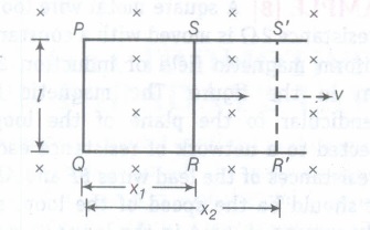
(i) Let RS moves with speed v rightward and also RS is at distances x1 and x2 from PQ at instants t1 at t2, respectively
∴ At t1 flux linked with loop 1, i.e. PQRS, φ1 = B(lx1) Similarly, at instant t2, flux linked with loop 2, i.e. PQR'S',
\(\phi_{2}=B\left(l x_{2}\right)\)
\(\therefore \text { Change in flux, } \Delta \phi=\phi_{2}-\phi_{1}=B l\left(x_{2}-x_{1}\right)=B l \Delta x\)
\(\Rightarrow \quad \frac{\Delta \varphi}{\Delta t}=B l \frac{\Delta x}{\Delta t}=B l v\) \(\left[\because v=\frac{\Delta x}{\Delta t}\right]\)
By Faraday's law, magnitude of induced emf, e = vB!.
(ii) If resistance of loop is R, then \(I=\frac{\nu B l}{R}\)
\(\therefore \text { Magnetic force }=I B l \sin 90^{\circ}=\left(\frac{v B l}{R}\right) B l\)
\(=\frac{v B^{2} l^{2}}{R} \quad\left[\because \sin 90^{\circ}=1\right]\)
∴ External force must be equal to magnetic force and in opposite directions.
\(\therefore \text { External force }=\frac{v B^{2} l^{2}}{R}\)
(iii) As, \(P=I^{2} R=\left(\frac{v B l}{R}\right)^{2} \times R=\frac{v^{2} B^{2} l^{2}}{R^{2}} \times R\)
\(\therefore \quad P=\frac{v^{2} B^{2} l^{2}}{R}\)
29.
(ii) Magnetic field lines due to a current carrying loop is given as below:
(iii) Magnetic field due to straight part
\(B=\int {\frac{\mu_0}{4\pi} \frac{Idl \times r}{r^{3}}}\)
For point 0, dl and r for each element of the straight segments AB and DE are parallel. Therefore, dIxr = 0. Hence, magnetic field due to straight segments is-zero.
Magnetic field at the centre due to circular point
= \(\frac{Magnetic \ field \ at \ the \ centre \ of \ circular \ coil }{2}\) [∵ Here, coil is stay]
\(=\frac{1}{2}(\frac{\mu_0 I}{2r})=\frac{\mu_0 I}{4r}\)
\(\Rightarrow B=\frac{\mu_0 I}{4r}=\frac{(4\pi \times10^{-7}\times 12}{4\times 2 \times 10^{-2}}=6\pi \times 10^{-5}T\)
30.
Principle: It works on the principle of mutual induction.
Working: When an alternating voltage is applied to the primary, the resulting current produces an alternating magnetic flux which links the secondary and induces an emf in it. We consider an ideal transformer in which the primary has negligible resistance and all the flux in the core links with both primary and secondary windings. Let cp be the flux in each turn in the core at a time due to current in the primary when a voltage Vp is applied to it.
\({ V }_{ s }={ E }_{ s }={ N }_{ s }\frac { d\phi }{ dt } \)
The alternating flux also induces an emf, called back emf in the primary given by
\({ V }_{ p }={ E }_{ p }=-{ N }_{ p }\frac { d\phi }{ dt } \)
But \({ E }_{ p }={ V }_{ p }\)
and \({ E }_{ s }={ V }_{ s }\)
So,
\({ V }_{ s }=-{ N }_{ s }\frac { d\phi }{ dt }\)
\( \\ { V }_{ p }=-{ N }_{ p }\frac { d\phi }{ dt } \)
\(\frac { { V }_{ s } }{ { V }_{ p } } =\frac { { N }_{ s } }{ { N }_{ p } } \)
For a step-up transformer, \(\frac { { V }_{ s } }{ { V }_{ p } } >1\)
So,
\(\frac { { V }_{ s } }{ { V }_{ p } } >1\)
(ii) Sources of energy loss in transformer (any two) Flux leakage / Joule's loss in the resistance of windings / Loss due to eddy currents / Hysteresis loss / Humming loss.
(iii) A step-up transformer steps up the voltage while it steps down the current. So the input and output power remain the same (provided there is no loss). Hence there is no violation of the principle of energy conservation.
31.
Phase difference between voltage and current,
\(tan\ \phi={{{X}_{L}-{X}_{C}}\over{R}}\)
and I0 = \({ { {V}_{0} }\over{Z } }={ { {V}_{0} }\over{ \sqrt{{({X}_{L}-{X}_{C})}^{2}} +{R}^{2}} }\)
\(\therefore\) Expression of AC,
I = I0 sin \((\omega t-\phi)\)
Conditions for resonanceInductive reactance must be equal to capacitive reactance
i.e. XL= XC
As, XL= XC
\(\Rightarrow\) \({\omega}_{0}L={{1}\over{{\omega}_{0}C}}\)
\(\Rightarrow\) \({ \omega }_{ 0 }^{ 2 }={ { 1 }\over{ LC } }\Rightarrow {\omega}_{0}={ { 1 }\over{ \sqrt{LC} } }\)
where ,\({\omega}_{0}\)= resonant angular frequency Impedance becomes minimum and equal to ohmic resistance
i.e. Z = Z. minimum = R
AC becomes maximum
\(\therefore \) \({I}_{max}={{{V}_{max}}\over{{Z}_{min}}}={{{V}_{max}}\over{R}}\)
Voltage and current arrives in same phase.
Power factor
i.e. cos \(\phi={{{P}_{av}}\over{{V}_{rms}{I}_{rms}}}={{True\ Power}\over{Apparent\ Power}}\)
Also, \(cos\ \phi={{R}\over{Z}}={{R}\over{\sqrt{{R}^{2}+({X}_{L}-{X}_{C})^{2}}}}\)
The power factor is maximum
i.e. cos \(\phi\).= + 1, in L-C-R series AC circuit when circuit is in resonance. The power factor is minimum when phase angle between V and I is 90°, i.e. either pure inductive circuit or pure capacitive AC circuit.
32.
(a) In one revolution
Change of area, \(dA=\pi l^2\)
\(\therefore\) change of magnetic flux
\(d\phi =\vec { B } .\vec { dA } =B.dA{ \cos { 0 } }^{ \circ }\)
\(=B\pi l^{ 2 }\)
(i) Induced emf, \(\varepsilon \) \(=B\pi l^{ 2 }/T=B\pi l^{ 2 }/v\)
(ii) Induced current in the rod, \(I=\frac{\varepsilon }{R}=\frac{\pi vB l^2}{R}\)
(b) Force acting on the rod, F = IlB
\(=\frac{\pi vB^2 l^3}{R}\)
The external force required to rotate the rod opposes the Lorentz force acting on the rod/ external force acts in the direction opposite the Lorentz force
(c) Power required to rotate the rod
Power = Force X velocity
P = Fx v
\(=\frac{\pi vB^2 l^3}{R}\times v\)
33.
34.
(a) Both Assertion and Reason are true and Reason is the correct explanation of Assertion.
35.
(a): Both the assertion and reason are true and reason is the correct explanation of assertion. When the magnet falls, the magnetic flux through the copper ring increases and induced e.m.f. is produced in the ring. The induced emf so produced, opposes the motion of falling magnet. Therefore, the acceleration of the falling magnet will be less than that due to gravity.
36.
(i) (c) : Here \(L=0.12 \mathrm{H}, C=480 \mathrm{nF}^{\prime}=480 \times 10^{-9} \mathrm{~F}\)
\(R=23 \Omega, V=230 \mathrm{~V}\)
\(V_{0}=\sqrt{2} \times 230=325.22 \mathrm{~V}\)
\(I_{0}=\frac{V_{0}}{\sqrt{R^{2}+\left(\omega L-\frac{1}{\omega C}\right)^{2}}}\)
At resonance, \(\omega L-\frac{1}{\omega C}=0\)
\(\omega=\frac{1}{\sqrt{L C}}=\frac{1}{\sqrt{0.12 \times 480 \times 10^{9}}}=4166.67 \mathrm{rad} \mathrm{s}^{-1}\)
\(v_{R}=\frac{4166.67}{2 \times 3.14}=663.48 \mathrm{~Hz}\)
(ii) (a) : Current \(I_{0}=\frac{V_{0}}{R}=\frac{325.22}{23}=14.14 \mathrm{~A}\)
(iii) (b) : Maximum power \(P_{\max }=\frac{1}{2}\left(I_{0}\right)^{2} R\)
\(=\frac{1}{2} \times(14.14)^{2} \times 23=2299.3 \mathrm{~W}\)
(iv) (d) : Quality factor \(Q=\frac{X_{L}}{R}=\frac{\omega_{r} L}{R}\)
\(=\frac{4166.67 \times 0.12}{23}=21.74\)
(v) (b)
37.
(i) (c) :Ohm is the unit of capacitive reactance.
(ii) (a): Capacitive reactance \(X_{C}^{1}=\frac{1}{\omega C}=\frac{1}{2 \pi v C}\)
\(=\frac{1}{2 \pi \times 10^{6} \times 5 \times 10^{-6}}=0.032 \Omega\)
(iii) (b): In capacitive circuit, resistance to the flow of current is offered by the capacitor.
(iv) (b)
(v) (a): Current \(I_{v}=\frac{E_{v}}{X_{C}}=\frac{E_{v}}{1 / 2 \pi v C}=(2 \pi v C) E_{v}\)
\(I_{v}=2 \times 3.14 \times 50 \times 10^{-6} \times 200=6.28 \times 10^{-2} \mathrm{~A}\)

12th Standard CBSE Syllabus & Materials
12th Standard CBSE
CBSE 12th Computer Science Python Revision Tour I - New Previous year Question Papers Study Material - QB365 Set A
NEW12th Standard CBSE
CBSE 12th Business Studies Planning Important Questions And Answers Study Material - QB365 Set A
NEW12th Standard CBSE
CBSE 12th Business Studies Business Environment Important Questions And Answers Study Material - QB365 Set A
NEW12th Standard CBSE
CBSE 12th Business Studies Principles of Management Important Questions And Answers Study Material - QB365 Set A



NCERT Books

Syllabus

Exam Pattern

Sample Question Papers

Previous year Question Papers

Important Notes

MCQ Practice test

NCERT Exemplers

Case study Questions

Image Based Questions

Passage based Questions

HOT Questions

Value Based Questions

Model Questions Papers
NCERT ( Book Back ) Questions

Assertion and Reason
Important Questions And Answers

CBSE 12th Standard CBSE Subjects
CBSE Standards