100% FREE ACCESS
12th Standard CBSE Syllabus & Materials
12th Standard CBSE
CBSE 12th Economics Government Budget and the Economy Previous year Question Papers Study Material - QB365 Set A
NEW12th Standard CBSE
CBSE 12th Computer Science Interface Python with MySQL - New Previous year Question Papers Study Material - QB365 Set A
NEW12th Standard CBSE
CBSE 12th Computer Science Database Concept - New Previous year Question Papers Study Material - QB365 Set A
NEW12th Standard CBSE
CBSE 12th Computer Science Data Communication - New Previous year Question Papers Study Material - QB365 Set A
NEW12th Standard CBSE
CBSE 12th Computer Science Data Structures - New Previous year Question Papers Study Material - QB365 Set A
NEW12th Standard CBSE
CBSE 12th Computer Science Functions - New Previous year Question Papers Study Material - QB365 Set A

Published on: 24/09/2019
Electromagnetic Induction and Alternating Currents
Download CBSE Class 12th Standard CBSE Physics question papers, sample papers, important questions, and previous year solved papers in PDF format. Get free study materials, NCERT solutions, and exam preparation resources for Class 12th Standard CBSE Physics
Questions + Answers key
Take MCQ Physics Test
1.
Draw a schematic diagram of a step-up transformer. Explain its working principle. Deduce the expression for the secondary to primary voltage in terms of the number of turns in the two coils. In an ideal transformer, how is this ratio related to the current in the two coils ?
How is the transformer used in large scale transmission and distribution of electrical energy over long distances ?
2.
A resistor of \(400\Omega \) an inductor of \(\frac { 5 }{ \pi H } \)and a capacitor of \(\frac { 50 }{ \pi } \mu F\) are connected in series across a source of alternating voltage of 140 \(sin\ \pi t\ V\). Find the voltage (rms) across the resistor, the inductor and the capacitor. Is the algebraic sum of these voltage more than the source voltage? If yes, resolve the paradox.
3.
Derive an expression for average power in an A.C. circuit containing resistor only.
4.
What are conservative and non-conservative fields?
5.
What is the difference between electric field produced by stationary charges and moving charges?
6.
State Lenz's law and illustrate it with experiment.
7.
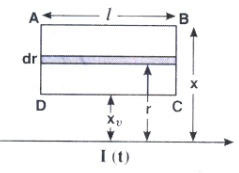
Consider an infinitely long wire carrying a current I (t), with \(\frac { dI }{ dt } =\lambda =constant.\) Find the current produced in the rectangular loop of wire ABCD if its resistance is R
8.
An LC circuit a 20 mH inductor and a \(50\mu F\) capacitor with an initial charge of 10 mC. The resistance of the circuit is negligible. Let the instant the circuit is closed be t = 0.
(a) What is the total energy stored initially? IS it conserved during LC oscillations?
(b) What is the natural frequency of the circuit?
(c) At what time is the energy stored
(i) completely electrical (i.e., stored in the capacitor)?
(ii) completely magnetic (i.e., stored in the inductor).
(d) At what times is the total energy shared equally between the inductor and the capacitor?
(e) If a resistor is inserted in the circuit, how much energy is eventually dissipated as heat?
1.
Principle: When an alternating voltage is applied to the primary, the resulting current produces an alternating magnetic flux which links the secondary and induces an emf in it (mutual induction).
Derivation :
The induced emf or voltages Es. in the secondary, with Ns, turns, is
\({ E }_{ s }=\frac { -{ N }_{ s }d\phi }{ dt } \)
The alternating flux also induces an emf, called back emf, in the primary. This is
\({ \varepsilon }_{ p }=\frac { -{ N }_{ p }d\phi }{ dt } \)
But
\({ \varepsilon }_{ s }={ V }_{ s }>{ \varepsilon }_{ p }={ V }_{ p }\)
therefore,
\({ V }_{ s }=\frac { -{ N }_{ s }d\phi }{ dt } \quad and\quad { V }_{ p }=\frac { -{ N }_{ p }d\phi }{ dt } \)
Hence
\(\frac { { V }_{ s } }{ { V }_{ p } } =\frac { { N }_{ s } }{ { N }_{ p } } \)
If the transformer is assumed to be 100% efficient (no energy losses), the power input is equal to the power output,
\(\frac { { V }_{ s } }{ { V }_{ p } } =\frac { { N }_{ s } }{ { N }_{ p } } =\frac { { I }_{ p } }{ { I }_{ s } } \)
The large-scale transmission and distribution of electrical energy over long distances are done with the use of transformers. The voltage output of the generator is stepped-up (so that current is reduced and consequently, the 12 R loss is cut down). It is then transmitted over long distances to an area sub-station near the consumers. There the voltage is stepped down. It is further stepped down at distributing sub-stations and utility poles before a power supply of 240 V reaches our homes.
2.
Applied voltage, V = 140 \(sin\ 100\pi t\ V\)
\(C \ = \ \frac { 50 }{ \pi } \mu F=\frac { 50 }{ \pi } \times { 10 }^{ -6 }F.\\ L \ = \ \frac { 5 }{ \pi } H, \ R=400\Omega \)
Comparing with V = V0 \(sin\ \omega t,\) we get
V0 = 140 V and \(\omega =100\pi \)
Inducting reactance,
\({ X }_{ L }=\omega L=100\pi \times \frac { 5 }{ \pi } =500\Omega \)
Capacitive reactance,
\({ X }_{ C }=\frac { 1 }{ \omega C } =\frac { 1 }{ 100\pi \times \frac { 50 }{ \pi } \times { 10 }^{ -6 } } \)
\(=200\Omega \quad \)
Impedance of the circuit,
\(Z=\sqrt { { R }^{ 2 }+({ X }_{ L }-{ X }_{ C })^{ 2 } } \)
\(=\sqrt { ({ 400) }^{ 2 }+({ 500-200) }^{ 2 } } \)
\( =\sqrt { 1600+900 } \ = \ 500\Omega \)
Maximum current in the circuit,
\({ I }_{ 0 }=\frac { { V }_{ 0 } }{ Z } =\frac { 140 }{ 500 }\)
\( { I }_{ rms }=\frac { { I }_{ 0 } }{ \sqrt { 2 } } =\frac { 140 }{ 500\times \sqrt { 2 } } =0.2\quad A\)
\({ V }_{ rms }\) across resistor, VR = Irms R
\(=0.2\times 400\ =\ 80V\)
Vrms across capacitor, VC = Irms XL
\(=0.2\times 200\ =\ 40V\)
Now, \(V\neq { V }_{ R }+{ V }_{ L }+{ V }_{ C }\)
Because VC,VL and VR are not in same phase, instead
\(V=\sqrt { { V }_{ R }^{ 2 }+({ V }_{ L }-{ V }_{ C })^{ 2 } } \)
\(=\sqrt { { 80 }^{ 2 }+({ 100-40) }^{ 2 } } =100V\)
Which is same as that of applied rms voltage.
3.
Power is the rate of doing work. In A.C current and voltage change at every moment. Since power is the product of instantaneous voltage and current, therefore it changes at every moment.
To determine average power in a circuit containing pure resistor, determine total energy spent in one cycle and divide it by the period.
Instantaneous power \(=EI=\left[ { E }_{ 0 }sin\omega t \right] \left[ { I }_{ 0 }sin\omega t \right] \)
Instantaneous work done in small interval dt is
\( \ dW=EI \ dt={ E }_{ 0 }{ I }_{ 0 }{ sin }^{ 2 }\omega t \ dt\)
\(W=\int _{ 0 }^{ T }{ { E }_{ 0 }{ I }_{ 0 }{ sin }^{ 2 }\omega t \ dt }\)
\(W={ E }_{ 0 }{ I }_{ 0 }\int _{ 0 }^{ T }{ { \left( \frac { 1-cos2\omega t }{ 2 } \right) }dt } \)
\(=\left[ \because \int _{ 0 }^{ T }{ dt } -\int _{ 0 }^{ T }{ cos2\omega t } \right]\)
\(or \ \ W=\frac { { E }_{ 0 }{ I }_{ 0 } }{ 2 } \left[ T-0 \right] =\frac { { E }_{ 0 }{ I }_{ 0 } }{ 2 } T\)
\( \left[ \because \int _{ 0 }^{ T }{ dt } -\int _{ 0 }^{ T }{ cos2\omega t } \right] =0\)
\(or \ \ { P }_{ av }=\frac { W }{ T } =\frac { { E }_{ 0 }{ I }_{ 0 } }{ 2 } =\frac { { E }_{ 0 } }{ \sqrt { 2 } } .\frac { { I }_{ 0 } }{ \sqrt { 2 } } \)
\(\ {P }_{ av }={ E }_{ v }{ I }_{ v }\)
\(\therefore\) Average power over a complete cycle of a.c through a resistor is the product of virtual voltage and virtual current.
4.
Consider a closed loop in which a current is flowing. The fact that a current is flowing implies of course that an electric field E exists along the loop. Small amount of work done in moving a unit charge through dl is given by \(-\overrightarrow { E } .\overrightarrow { d } l\)
When the work is done in taking unit charge along the entire closed loop is emf \(=\oint { \overrightarrow { E } .\overrightarrow { d } l } \)
\(e=\oint { \overrightarrow { E } .\overrightarrow { d } l } \)
\(\therefore \oint { \overrightarrow { E } .\overrightarrow { d } l } =-\frac { d\phi }{ dt } =e\)
\(So\oint { \overrightarrow { E } .\overrightarrow { d } l } \neq 0\)
Such fields are called non-conservative fields.
\(-\oint { \overrightarrow { E } .\overrightarrow { d } l } =-\frac { d\phi }{ dt } ,\) ....(1)
where \(\phi \) is the flux across the loop
Consider in contrast, an electric field caused by a charge at rest. If we take a unit charge from point a to point b, such field have the property that the work done
\({ W }_{ ab }=-\int _{ a }^{ b }{ \overrightarrow { E } .\overrightarrow { d } l } \) ....(2)
is independent of the path taken from a to b. If charge is taken along a closed path
\(\oint { \overrightarrow { E } .\overrightarrow { d } l } =0\) ....(3)
This last equation is different from (2). The electric fields created by changing magnetic field thus have a somewhat different character compared to electric fields due to stationary charges.
The field where the closed line integral of electric field is zero \(\left( \oint { \overrightarrow { E } .\overrightarrow { d } l } =0 \right) \) is called conservative field.
5.
Consider a closed loop in which a current is flowing. The fact that a current is flowing implies of-course that an electric field E exists along the loop. Small amount of work done in moving a unit charge through dl is given by \(-\overrightarrow { E } .\overrightarrow { d } l\)
When the work is done in taking unit charge along the entire closed loop is emf \(=\oint { \overrightarrow { E } .\overrightarrow { d } l } \)
\(e=\oint { \overrightarrow { E } .\overrightarrow { d } l } \)
\(\therefore \oint { \overrightarrow { E } .\overrightarrow { d } l } =-\frac { d\phi }{ dt } =e\)
\(So\oint { \overrightarrow { E } .\overrightarrow { d } l } \neq 0\)
Such fields are called non-conservative fields.
\(-\oint { \overrightarrow { E } .\overrightarrow { d } l } =-\frac { d\phi }{ dt } ,\) ....(1)
where \(\phi \) is the flux across the loop
Consider in contrast, an electric field caused by a charge at rest. If we take a unit charge from point a to point b, such field have the property that the work done
\({ W }_{ ab }=-\int _{ a }^{ b }{ \overrightarrow { E } .\overrightarrow { d } l } \) ....(2)
is independent of the path taken from a to b. If charge is taken along a closed path
\(\oint { \overrightarrow { E } .\overrightarrow { d } l } =0\) ....(3)
This last equation is different from (2). The electric fields created by changing magnetic field thus have a somewhat different character compared to electric fields due to stationary charges.
The field where the closed line integral of electric field is zero \(\left( \oint { \overrightarrow { E } .\overrightarrow { d } l } =0 \right) \) is called conservative field.
6.
Lenz's law. It states that the direction of induced current (or e.m.f.) is such that it always opposes the cause producing it. This law gives the direction of an induced current in terms of the cause of the current. An induced current in a coil is always due to change of magnetic flux linking the coil. The induced current will have its own associated magnetic flux of induced current will be such as to oppose the change of the primary magnetic flux.
Experimental verification of Lenz's law:
Let us connect the two ends of a coil of few turns to a cell C and a galvanometer G through a two-way key having terminals 1, 2 and 3 as shown in Fig. Put the plug between gap 1 and 2, the current in the upper face of the coil is in anticlockwise direction of N-pole is produced on this upper face. Let the galvanometer shows deflection to the right side. Now remove the key from gaps 1 and 2 and insert between 2 and 3, so the cell C is cut off. Bring N-pole of a bar magnet towards the upper face of the coil, the deflection produced in the galvanometer is again towards right. It means that the upper face of the coil becomes N-pole and repels the incoming magnet. Now take the magnet away from the coil, the deflection in the galvanometer is now towards left i.e. S-pole is formed at the upper end of the coil and it attracts the N-pole of the magnet.
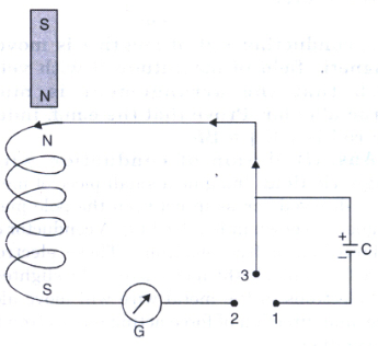
Thus we find that whether the magnet is taken towards or away from the coil, the direction of induced e.m.f. is such that it always opposes the motion of the magnet as predicted by Lenz's law.
7.
The magnetic field at strip at a distance r from a current carrying conductor is given by (out of paper)
Magnetic flux through the rectangular loop of width are
\(d\phi =\frac { { \mu }_{ 0 }I }{ 2\pi r } \times ldr\)
Total flux through the rectangular loop ABCD
\(\phi =\int { d\phi } =\frac { { \mu }_{ 0 }I }{ 2\pi } l\int _{ { x }_{ 0 } }^{ x }{ \frac { 1 }{ r } dr=\frac { { \mu }_{ 0 }I }{ 2\pi } } l\quad ln\frac { x }{ { x }_{ 0 } } \) ....(1)
or \(LI=\frac { { \mu }_{ 0 }Il }{ 2\pi } ln\frac { x }{ { x }_{ 0 } } \)
or \(L=\frac { { \mu }_{ 0 }l }{ 2\pi } ln\frac { x }{ { x }_{ 0 } } \)
\(\therefore \) Induced current \(=\frac { e }{ R } =\frac { L }{ R } \frac { dI }{ dt } =\frac { L }{ R } \lambda \)
\(=\frac { { \mu }_{ 0 }l\lambda }{ 2\pi R } ln\frac { x }{ { x }_{ 0 } } \)
8.
(a) 1.0 J, yes
(b) \(\omega \) = 103 rad s-1, v = 159 Hz
(c) 1.0 J

12th Standard CBSE Syllabus & Materials
12th Standard CBSE
CBSE 12th Computer Science Python Revision Tour I - New Previous year Question Papers Study Material - QB365 Set A
NEW12th Standard CBSE
CBSE 12th Business Studies Planning Important Questions And Answers Study Material - QB365 Set A
NEW12th Standard CBSE
CBSE 12th Business Studies Business Environment Important Questions And Answers Study Material - QB365 Set A
NEW12th Standard CBSE
CBSE 12th Business Studies Principles of Management Important Questions And Answers Study Material - QB365 Set A



CBSE 12th Standard CBSE Subjects
CBSE Standards