100% FREE ACCESS
12th Standard CBSE Syllabus & Materials
12th Standard CBSE
CBSE 12th Economics Government Budget and the Economy Previous year Question Papers Study Material - QB365 Set A
NEW12th Standard CBSE
CBSE 12th Computer Science Interface Python with MySQL - New Previous year Question Papers Study Material - QB365 Set A
NEW12th Standard CBSE
CBSE 12th Computer Science Database Concept - New Previous year Question Papers Study Material - QB365 Set A
NEW12th Standard CBSE
CBSE 12th Computer Science Data Communication - New Previous year Question Papers Study Material - QB365 Set A
NEW12th Standard CBSE
CBSE 12th Computer Science Data Structures - New Previous year Question Papers Study Material - QB365 Set A
NEW12th Standard CBSE
CBSE 12th Computer Science Functions - New Previous year Question Papers Study Material - QB365 Set A

Published on: 15/02/2019
Electromagnetic Induction and Alternating Currents Important Questions
Download CBSE Class 12th Standard CBSE Physics question papers, sample papers, important questions, and previous year solved papers in PDF format. Get free study materials, NCERT solutions, and exam preparation resources for Class 12th Standard CBSE Physics
Questions + Answers key
Take MCQ Physics Test
1.
Describe briefly, with the help of a labelled diagram, the basic elements of an A.C. generator. State its underlying principle. Show diagrammatically how an alternating emf is generated by a loop of wire rotating in a magnetic field. Write the expression for the instantaneous value of the emf induced in the rotating loop
2.
(a) Draw a schematic arrangement for winding of primary and secondary coil in a transformer when the two coils are wound on top of each other.
(b) State the underlying principle of a transformer and obtain the expression for the ratio of secondary to primary voltage in terms of the
(i) number of secondary and primary windings and
(ii) primary and secondary currents.
(c) Write the main assumption involved in deriving the above relations.
(d) Write any two reasons due to which energy losses may occur in actual transformers.
3.
A circuit containing 80 mH inductor and a \(60\mu F\) capacitor in series is connected to a 230 V, 50 Hz supply. The resistance in the circuit is negligible.
(i) Obtain the current amplitude and rms value.
(ii) Obtain tha rms value of potential drop across each element.
(iii) What is the average power transferred to inductor?
(iv) What is the average power transferred to capacitor?
(v) What is the total average power absorbed by the circuit?
4.
An electric lamp which runs at 80 volt d.c. and consumes 10 ampere is connected to 100 volt, 50 Hz a.c. mains. Calculate the inductance of the choke required.
5.
Distinguish between reactance and impedance. When a series combination of a coil of inductance L and a resistor of resistance R is connected across a 12 V, 50 Hz supply, a current of 0.5 A flows through the circuit. The current differs in phase from applied voltage by \(\frac { \pi }{ 3 } \) radian. Calculate the value of L and R.
6.
Study the circuits (a) and (b) shown in the figure answer the following question:

(i) Under which conditions would the rms currents in the two circuits be the same?
(ii) Can the rms current in circuit (b) be larger than that in (a)?
7.
A rectangular loop an area \(20cm\times 30cm\) is placed in magnetic field of 0.3T with its plane
(i) normal to the field
(ii) inclined 30\(^{0}\) to the field and
(iii) parallel to the field.
Find the flux linked with the coil in each case.
8.
An AC voltage \(V={ V }_{ m }sin \ \omega t\) is applied across an inducer of inductance L.Find the instantaneous power Pi supplied to the inductor. Show graphically the variation of Pi with \(\omega t\) .
9.
In the given figure, a bar magnet is quickly moved towards a conducting loop having a capacitor. Predict the polarity of the plates A and B of the capacitor.

10.
A small piece of metal wire is dragged across the gap between the pole pieces of a magnet in 10 s. The magnetic flux between the pole pieces is \(8 \times { 10 }^{ -4 }Wb.\) Find the magnitude of induced e.m.f.
11.
When a capacitor is connected in series LR circuit the alternating current flowing in the circuit increases. Explain why.
12.
When current in a coil changes with time, how is the back e.m.f. induced in the coil related to it?
13.
A light bulb and an open coil inductor are connected to an a.c. source. What happens to brightness of bulb when an iron rod is inserted into the inductor?
14.
How is capacitative reactance affected when frequency of a.c. supply is tripled?
15.
In India, domestic power supply is at 220 V, 50 hz, while in U.S.A, it is 110 V, 60 hz. Give one advantage and one disadvantages of 220 V supply over 110 V supply.
16.
How days the mutual inductance of a pair of coils hange when
(i) distance between the coils is increased
(ii) an iron sheet is placed between the two coils ?
17.
The self induced emf in a coil when current charges on it is given by.
18.
A vertical metallic pole falls down through the plane of magnetic meridian. Will any e.m.f. be induced between its ends ?
19.
A coil having n turns and resistance R is connected with a galvanometer of resistance 4R. This combination is moved in time t seconds from a magnetic flux \({ \phi }_{ 1 }\) Weber to \({ \phi }_{ 2 }\) Weber. The induced current in the circuit is :
\(\frac { { \phi }_{ 2 }-{ \phi }_{ 1 } }{ 5Rnt } \)
\(\frac { -n\left( { \phi }_{ 2 }-{ \phi }_{ 1 } \right) }{ 5Rt } \)
\(\frac { -\left( { \phi }_{ 2 }-{ \phi }_{ 1 } \right) }{ Rnt } \)
\(\frac { -n\left( { \phi }_{ 2 }-{ \phi }_{ 1 } \right) }{ Rt } \)
20.
Which of the following combinations should be selected for better tuning of an LCR circuit used for communication?
R = 20\(\Omega \), L = 1.5H, C = 35\(\mu\)F
R = 25\(\Omega \), L = 2.5H, C = 45\(\mu\)F
R = 15\(\Omega \), L = 3.5H, C = 30\(\mu\)F
R = 25\(\Omega \), L = 1.5H, C = 45\(\mu\)F
21.
A transformer is an electric device used for
producing direct current
producing alternating current
changing d.c. into a.c.
changing a.c. voltages
22.
The form factor of an a.c. generated is given by
\(\frac { { I }_{ av } }{ { I }_{ 0 } } \)
\(\frac { { I }_{ 0 } }{ { I }_{ av } } \)
\(\frac { { I }_{ av } }{ { I }_{ v } } \)
\(\frac { { I }_{ v } }{ { I }_{ av } } \)
23.
The resistance of a coil for direct current is 10ohm. When a.c. is sent through the same coil, its resistance would be
10\(\omega\)
> 10ohm
< 10ohm
cannot say
24.
Choose the quality whose SI unit is not ohm.
Resistance
Reactance
Capaciatnce
Impedance
25.
Out of the following, choose the correct relation
1henry = \(\frac{1\ volt}{1\ ampere}\)
1henry = \(\frac{1\ amp}{1\ volt}\)
1 henry = \(\frac{1volt}{1\ amp/sec}\)
1 henry = \(\frac{1volt}{1\ amp\ .\ sec}\)
1.
It works on the principle of electromagnetic induction, i.e. when a coil continuously rotates in a magnetic field, the magnetic flux associated with it keeps on changing; thus an emf is induced in it.
(b) When the coil rotates in a magnetic field, its effective area i.e. A cos \(\theta \) , (i.e. area normal to the magnetic field) keeps on changing. Hence magnetic flux \(\phi \) = NBAcos S, keeps on changing.
(c) Let the coil be rotating with angular velocity 'm',
at any instant 't' when the normal to the plane of the coil makes an angle \(\theta \) with the magnetic field. Hence magnetic flux, 12 \(\phi \) = NBA cos mt, Therefore induced emf (e)
\(\epsilon =-\frac { d\phi }{ dt } \)
\(\Rightarrow \epsilon =NBA\omega sin\quad \omega t\)
Induced emf will be maximum when mt = 90° 12 Hence, max = NBA\(\omega \)
Direction of induced emf can be determined using Flemming's Right-hand rule. Alternatively: Statement of the above rule.
2.
(a)
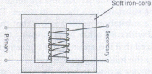
(b) Principle of a transformer: When alternating current flows through the primary coil, an emf is induced in the neighbouring (secondary) coil
Let \(\frac { d\phi }{ dt } \) be the rate of change of flux through each turn of the primary and the secondary coil
\(\frac { { \varepsilon }_{ 1 } }{ { \varepsilon }_{ 2 } } =-{ N }_{ 1 }\frac { d\phi }{ dt } /-{ N }_{ 2 }\frac { d\phi }{ dt } =\frac { { N }_{ 1 } }{ { N }_{ 2 } } \\ \frac { { V }_{ 1 } }{ { V }_{ 2 } } =\frac { { N }_{ 1 } }{ { N }_{ 2 } } \)
But for an ideal transformer,
\(\frac { { V }_{ 1 } }{ { V }_{ 2 } } =\frac { I_{ 2 } }{ I_{ 1 } } \)
From equation (1) and (2)
\(\frac { { V }_{ 1 } }{ { V }_{ 2 } } =\frac { N_{ 1 } }{ N_{ 2 } } =\frac { I_{ 2 } }{ I_{ 1 } } \)
(c) Main assumptions
(i) The primary resistance and current are small
(ii) The flux linked with the primary and secondary coils is same / there is no leakage of flux from the core.
(iii) Secondary current is small.
(d) Reason due to which energy loses may occur Flux leakage/Resistance of the coils/Eddy currents/Hysteresis.
3.
Given,
\(L=80mH=80\times { 10 }^{ -3 }H, \ R=0, \ v=50Hz\)
\(C=60\mu F=60\times { 10 }^{ -6 }F,\)
\(\omega =2\pi v=100\pi \ rad/s \)
\({ V }_{ rms }=230 \ V,\)
and \(\\ { V }_{ 0 }=\sqrt { 2{ V }_{ rms } } =\sqrt { 2 } \times 230V\)
(i) I0 = ? and Irms = ?
\(\begin{aligned} \Rightarrow I_0 & =\frac{V_0}{Z}=\frac{V_0}{\left|\omega L-\frac{1}{\omega C}\right|} \\ \end{aligned}\)
\(\begin{aligned} & =\frac{230 \sqrt{2}}{\left|100 \pi \times 80 \times 10^{-3}-\frac{1}{100 \pi \times 60 \times 10^{-6}}\right|} \\ \end{aligned}\)
\(\begin{aligned} =\frac{230 \sqrt{2}}{\left|8 \pi-\frac{1000}{6 \pi}\right|}=-11.63 \mathrm{~A} \\ \end{aligned}\)
\(\begin{aligned} I_{\mathrm{rms}} & =\frac{I_0}{\sqrt{2}}=\frac{-11.63}{\sqrt{2}}=8.23 \mathrm{~A} \end{aligned}\)
(ii) For L, VL = Irms \(\omega \)L = 8.23 \(\times\) 100\(\pi\)\(\times\)80 \(\times\)10-3
= 206.84 V
For C, \(V_C=I_{\mathrm{rms}} \frac{1}{\omega C}=8.23 \times \frac{1}{100 \pi \times 60 \times 10^{-6}}\)
= 436.84 V
Since, voltage across L and C are 180° out of phase, therefore they are subtracted.
Thus, applied rms voltage = 436.84 - 206.84
= 230.0 V
(iii) Average power transferred per cycle by source to inductor is always zero because of phase difference of \(\pi\)/2 between voltage and current through inductor.
(iv) Average power transferred per cycle by source to inductor is always zero because of phase difference of \(\pi\)/2 between voltage and current through inductor
(v) \(\therefore\) Total average power absorbed by the circuit is also zero.
4.
\(Here,\quad V=80V,\quad I=10A,\)
\(R=\frac { V }{ I } =\frac { 80 }{ 10 } =8\Omega \)
\({ E }_{ v }=100V,\quad v=50Hz,\quad { I }_{ v }=I=10A,\quad L=?\)
If Z is impedance of lamp and choke coil,
\(then \ Z=\frac { { E }_{ v } }{ { I }_{ v } } =\frac { 100 }{ 10 } =10\Omega \)
\(As \ { R }^{ 2 }+{ X }_{ L }^{ 2 }={ Z }^{ 2 }\)
\(\\ \therefore \ \ { X }_{ L }^{ 2 }={ Z }^{ 2 }-{ R }^{ 2 }={ 10 }^{ 2 }-{ 8 }^{ 2 }=36, \ { X }_{ L }=6\Omega \)
\(Now \ \ \ { X }_{ L }=\omega l=2\pi vL\)
\(\\ \therefore \ \ L=\frac { { X }_{ L } }{ 2\pi v } =\frac { 6\times 7 }{ 2\times 22\times 50 } =1.9\times { 10 }^{ -2 }H\)
5.
0.066 H, \(12\Omega \)
6.
Let (Irms)a = rms current in circuit (a)
(Irms)b = rms current in circuit (b)
\({ \left( I_{ rms } \right) }_{ a }=\frac { { V }_{ rms } }{ Z } =\frac { V }{ R } \)
\({ \left( I_{ rms } \right) }_{ b }=\frac { { V }_{ rms } }{ Z } b\)
\(=\frac { V }{ \sqrt { { R }^{ 2 }+\left( { X }_{ L }-{ X }_{ C } \right) ^{ 2 } } } \)
When \(({ I }_{ rms })_{ a } =({ I }_{ rms })_{ b }\)
\(R=\sqrt { { R }^{ 2 }+\left( { X }_{ L }-{ X }_{ C } \right) ^{ 2 } } \)
\(\Rightarrow \ { X }_{ L }={ X }_{ C }\) in resonance condition
(ii) As, \( Z\ge R\)
\(\Rightarrow \frac { ({ I }_{ rms })_{ a } }{ ({ I }_{ rms })_{ a } } =\frac { \sqrt { R=\sqrt { { R }^{ 2 }+\left( { X }_{ L }-{ X }_{ C } \right) ^{ 2 } } } }{ R } \)
\(=\frac { Z }{ R } \ \ge 1\)
\(({ I }_{ rms })_{ a }\ge ({ I }_{ rms })_{ b }\)
No, the rms current in circuit (b) cannot be larger than that in (a)
7.
Here, A = \(20cm\times 30cm\)
= \(6\times { 10 }^{ -2 }{ m }^{ -2 }\)
B = 0.3T
Let \(\theta \) be the angle made by field B with the normal to the plane of the coil.
(i) Here, \(\theta \) = 90\(^{0}\)- 90\(^{0}\) = 0\(^{0}\)
So, flux, \(\phi \)= BA cos\(\theta \)
\(\phi =0.3\times 6\times { 10 }^{ -2 }\times cos{ 0 }^{ \circ }\)
\(=1.8\times { 10 }^{ -2 }Wb\) (1)
(ii) Here, \(\theta \) = 90\(^{0}\)- 30\(^{0}\)
= 60\(^{0}\)
\(\phi =0.3\times 6\times { 10 }^{ -2 }\times cos{ 60 }^{ \circ }\\ \phi =0.9\times { 10 }^{ -2 }Wb\)
(iii) Here, \(\theta \) = 90\(^{0}\)
\(\phi =0.3\times 6\times { 10 }^{ -2 }\times cos{ 90 }^{ \circ }\\ \phi =0\)
8.
In an inductor, the current lags the voltage by 900 . If the source voltage is sinusoidal, then the current is also sinusoidal but shifted in phase. The instantaneous power defined as the product of the instantaneous voltage and current can also be seen to be sinusoidal in time. However, in contrast to the resistive load, the instantaneous power in the inductor goes negative for part of the cycle of the source driving it.
As, \(V(t)={ V }_{ m }\sin { \omega t } \)
\(I(t)=-{ I }_{ m }cos\omega t\)
instantaneous power Pi = V(t).I(t)
\(={ V }_{ m }sinn\omega t\times (-{ I }_{ m }cos\omega t)\)
\(=-\frac { { V }_{ m }{ I }_{ m } }{ 2 } \times 2sin\omega tcos\omega t\)
\(=-\frac { { V }_{ m }{ I }_{ m } }{ 2 } [sin\omega t+sin\ 0]\)
\(=-\frac { { V }_{ m }{ I }_{ m } }{ 2 } sin2\omega t\)
The variation of Pi with \(\omega t\) is as given in the figure.

The instantaneous power altertes positive and negative at twice the ferquency of source supplying it.
9.
Since the North pole of the bar magnet is approachng the loop, therefore the induced current wall flow in such a way that when loop viewed from left side. it will behave like a north pole and when viewed from right side, it will behave like a South pole. So, the flow of induced current in the loop will be clockwise. Hence, A acquires positive polarity and B acquires negative polarity.
10.
\(dt=10s,{ \phi }_{ 1 }=8 \times { 10 }^{ -4 }Wb, \ e=?,{ \phi }_{ 2 }=0\)
\(e=\frac { -d\phi }{ dt } =\frac { -({ \phi }_{ 2 }-{ \phi }_{ 1 }) }{ dt } =\frac { -(0-8 \times { 10 }^{ -4 }) }{ 10 }\)
\(=8 \times { 10 }^{ -5 }V\)
11.
In LR circuit, the impedance is given by
\({ Z }_{ L }=\sqrt { { R }^{ 2 }+{ X }_{ L }^{ 2 } } \quad ...(i)\)
In LCR circuit, the impedance is given by
\(Z=\sqrt { { R }^{ 2 }+{ \left( { X }_{ L }-{ X }_{ C } \right) }^{ 2 } } \quad ...(ii)\)
From equations, (i) and (ii), we find that
\(Z<{ Z }_{ L }\)
\(since \ I=\frac { E }{ Z } \)
As Z decreases on connecting a capacitor in series with LR circuit, hence the current I in the circuit increases.
12.
The back emf in the coil opposes the change in the current as per Lenz's law.
13.
Current through the bulb
\({ I }_{ \upsilon }=\frac { { E }_{ \upsilon } }{ Z } =\frac { { E }_{ \upsilon } }{ \sqrt { { R }^{ 2 }+{ X }_{ L }^{ 2 } } } ,where\ { X }_{ L }=\omega L\)
On introducing an iron rod into the inductor its inductance L increases. \({ X }_{ L }={ \omega }L\) increases. Therefore, impedance Z increases. Hence brightness of bulb decreases.
14.
\(X_C=\frac{1}{\omega C}=\frac{1}{2 \pi \omega v C}\) therefore, when v is tripled
15.
For transfer of power \(\left( =V\times I \right) \) at higher voltage (220 V instead of 110 V), current carried by wires is just half. Therefore, such wires need not be very thick, saving lot of transmission material and reducing the cost of transmission. This is one advantage of 220 V supply. But to design a device of particular wattage, \(P=\frac { { V }^{ 2 } }{ R } \) , as \({ V }^{ 2 }\) is 4 times, R must be four times. If not, the dissipation of power in the form of heat will be larger on 220 V supply. This is one disadvantage of this supply.
16.
(i) On increasing distance between the two coils, magnetic flux passing from one coil to the other decreases. Therefore, mutual inductance decreases.
(ii) When an iron sheet is placed between the two coils, mutual inductance increases because \(M\propto \mu \) (the permeability).
17.
\(e=-L \frac{d l}{d t}\)
Where symbols have usual meaning.
18.
No, because the pole intercepts neither H nor V.
19.
(b)
\(\frac { -n\left( { \phi }_{ 2 }-{ \phi }_{ 1 } \right) }{ 5Rt } \)
20.
(c)
R = 15\(\Omega \), L = 3.5H, C = 30\(\mu\)F
21.
(d)
changing a.c. voltages
22.
(d)
\(\frac { { I }_{ v } }{ { I }_{ av } } \)
23.
(b)
> 10ohm
24.
(c)
Capaciatnce
25.
(c)
1 henry = \(\frac{1volt}{1\ amp/sec}\)

12th Standard CBSE Syllabus & Materials
12th Standard CBSE
CBSE 12th Computer Science Python Revision Tour I - New Previous year Question Papers Study Material - QB365 Set A
NEW12th Standard CBSE
CBSE 12th Business Studies Planning Important Questions And Answers Study Material - QB365 Set A
NEW12th Standard CBSE
CBSE 12th Business Studies Business Environment Important Questions And Answers Study Material - QB365 Set A
NEW12th Standard CBSE
CBSE 12th Business Studies Principles of Management Important Questions And Answers Study Material - QB365 Set A



CBSE 12th Standard CBSE Subjects
CBSE Standards