100% FREE ACCESS
12th Standard CBSE Syllabus & Materials
12th Standard CBSE
CBSE 12th Economics Government Budget and the Economy Previous year Question Papers Study Material - QB365 Set A
NEW12th Standard CBSE
CBSE 12th Computer Science Interface Python with MySQL - New Previous year Question Papers Study Material - QB365 Set A
NEW12th Standard CBSE
CBSE 12th Computer Science Database Concept - New Previous year Question Papers Study Material - QB365 Set A
NEW12th Standard CBSE
CBSE 12th Computer Science Data Communication - New Previous year Question Papers Study Material - QB365 Set A
NEW12th Standard CBSE
CBSE 12th Computer Science Data Structures - New Previous year Question Papers Study Material - QB365 Set A
NEW12th Standard CBSE
CBSE 12th Computer Science Functions - New Previous year Question Papers Study Material - QB365 Set A

Published on: 02/11/2025
Download CBSE Class 12th Standard CBSE Physics question papers, sample papers, important questions, and previous year solved papers in PDF format. Get free study materials, NCERT solutions, and exam preparation resources for Class 12th Standard CBSE Physics
Questions + Answers key
Take MCQ Physics Test
1.
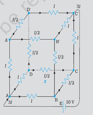
A battery of 10 V and negligible internal resistance is connected across the diagonally opposite corners of a cubical network consisting of 12 resistors each of resistance 1 \(\Omega\) (Figure). Determine the equivalent resistance of the network and the current along each edge of the cube.
2.
A closely wound solenoid 80 cm long has 5 layers of windings of 400 turns each. The diameter of the solenoid is 1.8 cm. If the current carried is 8.0 A, estimate the magnitude of B inside the solenoid near its centre.
3.
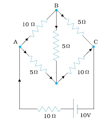
Determine the current in each branch of the network shown in Figure
4.
The four arms of a Wheatstone bridge Figure have the following resistances:
AB = 100Ω, BC = 10Ω, CD = 5Ω, and DA = 60Ω.
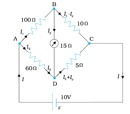
A galvanometer of 15Ω resistance is connected across BD. Calculate the current through the galvanometer when a potential difference of 10 V is maintained across AC.
5.
Given bellow shows a series LCR circuit connected to a variable frequency 230 V source. L = 5.0 H, C = 80μF, R = 40 Ω.
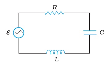
(a) Determine the source frequency which drives the circuit in resonance.
(b) Obtain the impedance of the circuit and the amplitude of current at the resonating frequency.
(c) Determine the rms potential drops across the three elements of the circuit. Show that the potential drop across the LC combination is zero at the resonating frequency.
6.
A series LCR circuit with R = 20 Ω, L = 1.5 H and C = 35 μF is connected to a variable-frequency 200 V ac supply. When the frequency of the supply equals the natural frequency of the circuit, what is the average power transferred to the circuit in one complete cycle?
7.
(a) The peak voltage of an AC supply is 300 V. What is its rms voltage?
(b) The rms value of current in an AC circuit is 10 A. What is the peak current?
8.
A wire of radius 0.8 cm carries a current of 100 A which is uniformly distributed over its cross-section. Find the magnetic field (a) at 0.2 cm from the axis of the wire (b) at the surface of the wire and (c) at a point outside the wire 0.4 cm from the surface of the wire. Neglect the permeability of the material of wire.
9.
In a chamber, a uniform magnetic field of 6.5 G (1 G = 10–4 T) is maintained. An electron is shot into the field with a speed of 4.8 x 10⁶ m s–1 normal to the field. Explain why the path of the electron is a circle. Determine the radius of the circular orbit. (e = 1.5 x 10⁻¹⁹ C, me = 9.1 x 10⁻³¹ kg)
10.
A storage battery of emf 8.0 V and internal resistance 0.5 \(\Omega\) is being charged by a 120V dc supply using a series resistor of 15.5 \(\Omega\). What is the terminal voltage of the battery during charging? What is the purpose of having a series resistor in the charging circuit?
1.
The network is not reducible to a simple series and parallel combinations of resistors. There is, however, a clear symmetry in the problem which we can exploit to obtain the equivalent resistance of the network.
The paths AA', AD and AB are obviously symmetrically placed in the network. Thus, the current in each must be the same, say, I. Further, at the corners AA', B and D, the incoming current I must split equally into the two outgoing branches. In this manner, the current in all the 12 edges of the cube are easily written down in terms of I, using Kirchhoff’s first rule and the symmetry in the problem. Next take a closed loop, say, ABCC'EA, and apply Kirchhoff’s second rule:
–IR – (1/2)IR – IR + \(\epsilon\) = 0
where R is the resistance of each edge and e the emf of battery. Thus,
\(\epsilon = \frac{5}{2}IR\)
The equivalent resistance Req of the network is
\(R_{eq}= \frac{\epsilon}{3I}=\frac{5}{6}R\)
For R = 1 Ω, Req = (5/6) Ω and for e = 10 V, the total current (= 3I ) in
the network is
3I = 10 V/(5/6) Ω = 12 A, i.e., I = 4 A
The current flowing in each edge can now be read off from the figure.
2.
Length of the solenoid, l = 80 cm = 0.8 m
There are five layers of windings of 400 turns each on the solenoid.
∴ Total number of turns on the solenoid, N = 5 x 400 = 2000
Diameter of the solenoid, D = 1.8 cm = 0.018 m
Current carried by the solenoid, I = 8.0 A
Magnitude of the magnetic field inside the solenoid near its centre is given by the relation,
\(B=\frac{\mu_{0} N I}{l}\)
Where,
μ0 = Permeability of free space = 4π x 10–7 T m A–1
\(B=\frac{4 \pi \times 10^{-7} \times 2000 \times 8}{0.8}\)
\(=8 \pi \times 10^{-3}=2.512 \times 10^{-2} T\)
Hence, the magnitude of the magnetic field inside the solenoid near its centre is 2.512 x 10⁻² T.
3.
Current flowing through various branches of the circuit is represented in the given figure.
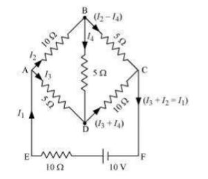
I1 = Current flowing through the outer circuit
I2 = Current flowing through branch AB
I3 = Current flowing through branch AD
I2 - I4 = Current flowing through branch BC
I3 + I4 = Current flowing through branch CD
I4 = Current flowing through branch BD
For the closed circuit ABDA, potential is zero i.e.,
10I2 + 5I4 - 5I3 = 0
2I2 + I4 - I3 = 0
I3 = 2I2 + I4 … (1)
For the closed circuit BCDB, potential is zero i.e.,
5(I2 - I4) - 10(I3 + I4) - 5I4 = 0
5I2 + 5I4 - 10I3 - 10I4 - 5I4 = 0
5I2 - 10I3 - 20I4 = 0
I2 = 2I3 + 4I4 … (2)
For the closed circuit ABCFEA, potential is zero i.e.,
-10 + 10 (I1) + 10(I2) + 5(I2 - I4) = 0
10 = 15I2 + 10I1 - 5I4
3I2 + 2I1 - I4 = 2 … (3)
From equations (1) and (2), we obtain
I3 = 2(2I3 + 4I4) + I4
I3 = 4I3 + 8I4 + I4
- 3I3 = 9I4
- 3I4 = + I3 … (4)
Putting equation (4) in equation (1), we obtain
I3 = 2I2 + I4
- 4I4 = 2I2
I2 = - 2I4 … (5)
It is evident from the given figure that,
I1 = I3 + I2 … (6)
Putting equation (6) in equation (1), we obtain
3I2 +2(I3 + I2) - I4 = 2
5I2 + 2I3 - I4 = 2 … (7)
Putting equations (4) and (5) in equation (7), we obtain
5(- 2 I4) + 2(- 3 I4) - I4 = 2
- 10I4 - 6I4 - I4 = 2
17I4 = - 2
\(I_{4}=-\frac{2}{17} A\)
Equation (4) reduces to
I3 = - 3(I4)
\(=-3\left(-\frac{2}{17}\right)=\frac{6}{17} A\)
\(I_{2}=-2\left(I_{4}\right)\)
\(=-2\left(-\frac{2}{17}\right)=\frac{4}{17} A\)
\(I_{2}-I_{4}=\frac{4}{17}-\left(-\frac{2}{17}\right)=\frac{6}{17} A\)
\(I_{3}+I_{4}=\frac{6}{17}+\left(-\frac{2}{17}\right)=\frac{4}{17} A\)
\(I_{1}=I_{3}+I_{2}\)
\(=\frac{6}{17}+\frac{4}{17}=\frac{10}{17} A\)
Therefore, current in branch \(A B=\frac{4}{17} A\)
In branch BC \(=\frac{6}{17} A\)
In branch CD = \(-\frac{4}{17} A\)
In branch AD = \(\frac{6}{17} A\)
In branch BD = \(\left(-\frac{2}{17}\right) A\)
Total current = \(\frac{4}{17}+\frac{6}{17}+\frac{-4}{17}+\frac{6}{17}+\frac{-2}{17}=\frac{10}{17} A\)
4.
Considering the mesh BADB, we have
100I1 + 15Ig - 60I2 = 0
or 20I1 + 3Ig - 12I2 = 0
Considering the mesh BCDB, we have
10 (I1 - Ig) - 15Ig - 5 (I2 + Ig) = 0
10I1 - 30Ig - 5I2 = 0
2I1 - 6Ig - I2 = 0
Considering the mesh ADCEA,
60I2 + 5 (I2 + Ig) = 10
65I2 + 5Ig = 10
13I2 + Ig = 2
Multiplying by 10
20I1 - 60Ig - 10I2 = 0
From we have
63Ig - 2I2 = 0
I2 = 31.5Ig
Substituting the value of I2 into we get
13 (31.5Ig ) + Ig = 2
410.5 Ig = 2
Ig = 4.87 mA
5.
Given that the Inductance of the inductor in the circuit is, L = 5.0 H
Given that the Capacitance of the capacitor in the circuit is , C = 80 μH = 80 x 10 - 6 F
Given that Resistance of the resistor in the circuit, R = 40 Ω
Value of Potential of the variable voltage supply, V = 230 V
(a) We know that the Resonance angular frequency can be obtained by the following relation :
\(\omega_{r}=\frac{1}{\sqrt{L C}} \omega_{r}=\frac{1}{\sqrt{5 x 80 x 10-6}} \omega_{r}=\frac{10^{3}}{20}=50 \mathrm{rad} / \mathrm{sec}\)
Thus, the circuit encounters resonance at a frequency of 50 rad/s.
(b) We know that the Impedance of the circuit can be calculated by the following relation :
\(Z=\sqrt{R^{2}+\left(X_{L}-X_{C}\right)^{2}}\)
At resonant condition,
X L = X C
Z = R = 40 Ω
At resonating frequency amplitude of the current can be given by the following relation :
\(I_{0}=\frac{V_{0}}{Z}\)
where,
V 0 = peak voltage = \(\sqrt{2} V\)
Therefore,
\(I_{0}=\frac{\sqrt{2 V}}{Z}=\frac{\sqrt{2} \times 230}{40}=8.13 \mathrm{~A}\)
Thus, at resonant condition, the impedance of the circuit is calculated to be 40 Ω and the amplitude of the current is found to be 8.13 A
c) rms potential drop across the inductor in the circuit,
( V L ) rms = I x ω r L
Where,
\(I_{r m s}=\frac{I_{0}}{\sqrt{2}}=\frac{\sqrt{2} V}{\sqrt{2} Z}=\frac{230}{40}=\frac{23}{4} A\)
Therefore, ( V L ) rms
\(\frac{23}{4} \times 50 \times 5=1437.5 \mathrm{~V}\)
We know that the Potential drop across the capacitor can be calculated with the following relation :
\(\left(V_{c}\right)_{r m s}=I \times \frac{1}{\omega_{r} C}=\frac{23}{4} \times \frac{1}{50 \times 80 \times 10^{-6}}=1437.5 V\)
We know that the Potential drop across the resistor can be calculated with the following relation :
\(\left(V_{R}\right)_{r m s}=I R=\frac{23}{4} \times 40=230 \mathrm{~V}\)
Now, Potential drop across the LC connection can be obtained by the following relation :
V L C = I ( X L − X C )
At resonant condition,
X L = X C
V L C = 0
Therefore, it has been proved from the above equation that the potential drop across the LC connection is equal to zero at a frequency at which resonance occurs.
6.
The supply frequency and the natural frequency are equal at resonance condition in the circuit.
Given Resistance of the resistor, R = 20 Ω
Given Inductance of the inductor, L = 1.5 H
Given Capacitance of the capacitor , C = 35 μF = 30 x 10 - 6 F
An AC source with a voltage of V = 200 V is connected to the LCR circuit,
We know that the Impedance of the above combination can be calculated by the following relation,
\(Z=\sqrt{R^{2}+\left(X_{L}-X_{C}\right)^{2}}\)
At resonant condition in the circuit , X L = X C
Therefore , Z = R = 20 Ω
We know that Current in the network is given by the relation :
\(I=\frac{V}{Z}=\frac{200}{20}=10 A\)
Therefore, the average power that is being transferred to the circuit in one full cycle :
V I = 200 x 10 = 2000 W
7.
a) Given: The peak voltage of supply is 100 V.
The rms voltage is give as,
v m = 2 ×V
Where, the peak value of supply voltage is v m and its rms value is V.
By substituting the given values in the above equation, we get
300= 2 ×V V= 300 2 =212.1 V
Thus, the value of rms voltage is 212.1V.
b) Given: The rms current in an ac circuit is 10 A.
The peak current in the circuit is given as,i m = 2 ×I
Where, the peak current in an ac circuit is i m and its rms value is I.
By substituting the given values in the above equation, we get
i m = 2 ×10 =14.1 A
Thus, the value of peak current in the given ac circuit is 14.1 A.
8.
Here, R = 0.8 cm = 8 x 10⁻³ m ;
I = 100 A
\((a) \ { B }_{ inside }=\frac { { \mu }_{ o } }{ 4\pi } \frac { 2Ir }{ { R }^{ 2 } } \)
\(={ 10 }^{ -7 }\times \frac { 2\times 100\times { \left( 0.2\times { 10 }^{ -2 } \right) }^{ 2 } }{ { \left( 8\times { 10 }^{ -3 } \right) }^{ 2 } } \)
= 6.25 x 10⁻⁴ T
\((b) \ { B }_{ surface }=\frac { { \mu }_{ o } }{ 4\pi } \frac { 2I }{ { R } } ={ 10 }^{ -7 }\times \frac { 2\times 100 }{ 8\times { 10 }^{ -3 } } \)
= 2.5 x 10⁻⁵ T
(c) When point is outside the wire,
r = 0.8 + 0.4 = 1.2 cm = 1.2 x 10⁻² m.
\({ B }_{ outside }=\frac { { \mu }_{ o } }{ 4\pi } \frac { 2I }{ { r } } ={ 10 }^{ -7 }\times \frac { 2\times 100 }{ 1.2\times { 10 }^{ -2 } } \)
= 1.67 x 10⁻⁵ T.
9.
Magnetic field strength, B = 6.5 G = 6.5 x 10⁻⁴ T
Speed of the electron, v = 4.8 x 10⁶ m/s
Charge on the electron, e = 1.6 x 10⁻¹⁹ C
Mass of the electron, me = 9.1 x 10⁻³¹ kg
Angle between the shot electron and magnetic field, θ = 90°
Magnetic force exerted on the electron in the magnetic field is given as:
F = evB sinθ
This force provides centripetal force to the moving electron. Hence, the electron starts moving in a circular path of radius r.
Hence, centripetal force exerted on the electron,
\(F_{c}=\frac{m v^{2}}{r}\)
In equilibrium, the centripetal force exerted on the electron is equal to the magnetic force i.e.,
FC = F
\(\frac{m v^{2}}{r}=e v B \sin \theta\)
\(r=\frac{m v}{B e \sin \theta}\)
\(=\frac{9.1 \times 10^{-31} \times 4.8 \times 10^{6}}{6.5 \times 10^{-4} \times 1.6 \times 10^{-19} \times \sin 90^{\circ}}\)
= 4.2 x 10 -2 m = 4.2 cm
Hence, the radius of the circular orbit of the electron is 4.2 cm.
10.
Emf of the storage battery, E = 8.0 V
Internal resistance of the battery, r = 0.5 Ω
DC supply voltage, V = 120 V
Resistance of the resistor, R = 15.5 Ω
Effective voltage in the circuit = V1
R is connected to the storage battery in series. Hence, it can be written as
V1 = V - E
V1 = 120 - 8 = 112 V
Current flowing in the circuit = I, which is given by the relation,
\(I=\frac{V^{1}}{R+r}\)
\(=\frac{112}{15.5+5}=\frac{112}{16}=7 A\)
Voltage across resistor R given by the product, IR = 7 x 15.5 = 108.5 V
DC supply voltage = Terminal voltage of battery + Voltage drop across R
Terminal voltage of battery = 120 - 108.5 = 11.5 V
A series resistor in a charging circuit limits the current drawn from the external source. The current will be extremely high in its absence. This is very dangerous.

12th Standard CBSE Syllabus & Materials
12th Standard CBSE
CBSE 12th Computer Science Python Revision Tour I - New Previous year Question Papers Study Material - QB365 Set A
NEW12th Standard CBSE
CBSE 12th Business Studies Planning Important Questions And Answers Study Material - QB365 Set A
NEW12th Standard CBSE
CBSE 12th Business Studies Business Environment Important Questions And Answers Study Material - QB365 Set A
NEW12th Standard CBSE
CBSE 12th Business Studies Principles of Management Important Questions And Answers Study Material - QB365 Set A



NCERT Books

Syllabus

Exam Pattern

Sample Question Papers

Previous year Question Papers

Important Notes

MCQ Practice test

NCERT Exemplers

Case study Questions

Image Based Questions

Passage based Questions

HOT Questions

Value Based Questions

Model Questions Papers
NCERT ( Book Back ) Questions

Assertion and Reason
Important Questions And Answers

CBSE 12th Standard CBSE Subjects
CBSE Standards