100% FREE ACCESS
12th Standard CBSE Syllabus & Materials
12th Standard CBSE
CBSE 12th Economics Government Budget and the Economy Previous year Question Papers Study Material - QB365 Set A
NEW12th Standard CBSE
CBSE 12th Computer Science Interface Python with MySQL - New Previous year Question Papers Study Material - QB365 Set A
NEW12th Standard CBSE
CBSE 12th Computer Science Database Concept - New Previous year Question Papers Study Material - QB365 Set A
NEW12th Standard CBSE
CBSE 12th Computer Science Data Communication - New Previous year Question Papers Study Material - QB365 Set A
NEW12th Standard CBSE
CBSE 12th Computer Science Data Structures - New Previous year Question Papers Study Material - QB365 Set A
NEW12th Standard CBSE
CBSE 12th Computer Science Functions - New Previous year Question Papers Study Material - QB365 Set A

Published on: 21/05/2021
QB365 Provides the updated CASE Study Questions for Class 12 , and also provide the detail solution for each and every case study questions . Case study questions are latest updated question pattern from NCERT, QB365 will helps to get more marks in Exams
Download CBSE Class 12th Standard CBSE Physics question papers, sample papers, important questions, and previous year solved papers in PDF format. Get free study materials, NCERT solutions, and exam preparation resources for Class 12th Standard CBSE Physics
Questions + Answers key
Take MCQ Physics Test
1.
A transformer is an electrical device which is used for changing the a.c. voltages. It is based on the phenomenon of mutual induction i.e. whenever the amount of magnetic flux linked with a coil changes, an e.m.f is induced in the neighbouring coil. For. an ideal transformer, the resistances of the primary and secondary windings are negligible.
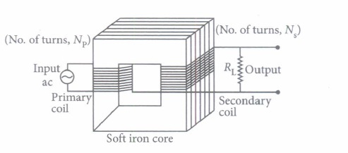
It can be shown that \(\frac{E_{s}}{E_{p}}=\frac{I_{p}}{I_{s}}=\frac{n_{s}}{n_{p}}=k\)
where the symbols have their standard meanings.
For a step up transformer \(n_{s}>n_{p} ; E_{s}>E_{p} ; k>1 ; \quad \therefore I_{s}
For a step down transformer \(n_{s}
The above relations are on the assumptions that efficiency of transformer is 100%.
lentlac ,effciency \(\eta=\frac{\text { output power }}{\text { intput power }}=\frac{E_{s} I_{s}}{E_{p} I_{p}}\)
(i) Which of the following quantity remains constant in an ideal transformer?
| (a) Current | (b) Voltage | (c) Power | (d) All of these |
(ii) Transformer is used to
| (a) convert ac to dc voltage | (b) convert de to ac voltage |
| (c) obtain desired dc power | (d) obtain desired ac voltage and current |
(iii) The number of turns in primary coil of a transformer is 20 and the number of turns in a secondary is 10. If the voltage across the primary is 220 ac V, what is the voltage across the secondary?
| (a) 100 ac V | (b) 120 ac V | (c) 110 ac V | (d) 220 ac V |
(iv) In a transformer the number of primary turns is four times that of the secondary turns. Its primary is connected to an a.c. source of voltage V. Then
| (a) current through its secondary is about four times that of the current through its primary |
| (b) voltage across its secondary is about four times that of the voltage across its primary. |
| (c) voltage across its secondary is about two times that of the voltage across its primary |
| (d) voltage across its secondary is about \(\frac{1}{2 \sqrt{2}}\) times that of the voltage across its primary |
(v) A transformer is used to light 100 W-110 V lamp from 220 V mains. If the main current is 0.5 A, the efficiency of the transformer is
| (a) 95% | (b) 99% | (c) 90% | (d) 96% |
2.
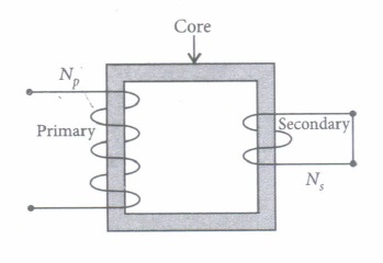
Step-down transformers are used to decrease or step-down voltages. These are used when voltages need to be lowered for use in homes and factories.
A small town with a demand of 800 kW of electric power at 220 V is situated 15 km away from an electric plant generating power at 440 V. The resistance of the two wire line carrying power is \(0.5 \Omega\) per km. The town gets power from the line through a 4000 - 220 V step-down transformer at a sub-station in the town.
(i) The value of total resistance of the wires is
| \(\text { (a) } 25 \Omega\) | \(\text { (b) } 30 \Omega\) | \(\text { (c) } 35 \Omega\) | \(\text { (d) } 15 \Omega\) |
(ii) The line power loss in the form of heat is
| (a) 550 kW | (b) 650 kW | (c) 600 kW | (d) 700 kW |
(iii) How much power must the plant supply, assuming there is negligible power loss due to leakage?
| (a) 600 kW | (b) 1600 kW | (c) 500 W | (d) 1400 kW |
(iv) The voltage drop in the power line is
| (a) 1700V | (b) 3000V | (c) 2000V | (d) 2800 V |
(v) The total value of voltage transmitted from the plant is
| (a) 500 V | (b) 4000 V | (c) 3000 V | (d) 7000 V |
3.
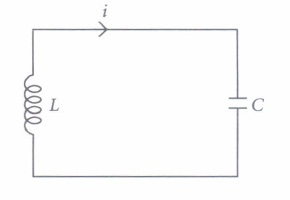
An LC circuit also called a resonant circuit, tank circuit or tuned circuit is an electric circuit consisting of an inductor represented by the letter L and a capacitor, represented by the letter C connected together. An LC circuit is an idealized model since it assumes there is no dissipation of energy due to resistance.
An LC circuit contains a 20 mH inductor and a \(50 \mu \mathrm{F}\) capacitor with an initial charge of 10 mC The resistance of the circuit is negligible. Let the instant the circuit is closed be t = 0.
(i) The total energy stored initially is
| (a) 5 J | (b) 3 J | (c) 10 J | (d) 1 J |
(ii) The natural frequency of the circuit is
| (a) 159.24 Hz | (b) 200.12 Hz | (c) 110.25 Hz | (d) 95 Hz |
(iii) At what time is the energy stored completely electrical?
| \(\text { (a) } T, 5 T, 9 T\) | \(\text { (b) } \frac{T}{2}, \frac{5 T}{2}, \frac{9 T}{2}\) | (c) 0, T, 2T, 3T | \(\text { (d) } 0, \frac{T}{2}, T, \frac{3 T}{2}\) |
(iv) At what time is the energy stored completely magnetic?
| \(\text { (a) } \frac{T}{2}, \frac{3 T}{2}, \frac{T}{4}\) | \(\text { (b) } \frac{T}{3}, \frac{T}{9}, \frac{T}{12}\) | (c) 0, 2T, 3T | \(\text { (d) } \frac{T}{4}, \frac{3 T}{4}, \frac{5 T}{4}\) |
(v) The value of XL is
| \(\text { (a) } 20 \Omega\) | \(\text { (b) } 40 \Omega\) | \(\text { (c) } 60 \Omega\) | \(\text { (d) } 50 \Omega\) |
1.
(i) (c) :In an ideal transformer, there is no power loss. The efficiency of an ideal transformer is \(\eta=1(i . e\) 100%) i.e. input power = output power.
(ii) (d): Transformer is used to obtain desired ac voltage and current.
(iii) (c): For a transformer \(\frac{V_{s}}{V_{p}}=\frac{N_{s}}{N_{p}}\)
where Ndenotes number of turns and V = voltage
\(\therefore \frac{V_{s}}{220}=\frac{10}{20} \quad \therefore V_{s}=110 \mathrm{ac} \mathrm{V}\)
(iv) (a): In a transformer the primary and secondary currents are related by
\(I_{s}=\left(\frac{N_{p}}{N_{s}}\right) I_{p}\)
and the voltages are related by
\(V_{s}=\left(\frac{N_{s}}{N_{p}}\right) V_{p}\)
where subscripts p and s refer to the primary and secondary of the transformer
Here, \(V_{p}=V, \frac{N_{p}}{N_{s}}=4 \quad \therefore \quad I_{s}=4 I_{p}\)
and \(V_{s}=\left(\frac{1}{4}\right) V=\frac{V}{4}\)
(v) (c): The efficiency of the transformer is \(\eta=\frac{\text { Output power }\left(P_{\text {out }}\right)}{\text { Input power }\left(P_{\text {in }}\right)} \times 100\)
Here, \(P_{\text {out }}=100 \mathrm{~W}, P_{\text {in }}=(220 \mathrm{~V})(0.5 \mathrm{~A})=110 \mathrm{~W}\)
\(\therefore \quad \eta=\frac{100 \mathrm{~W}}{110 \mathrm{~W}} \times 100 \approx 90 \%\)
2.
(i) (d): Resistance of the two wire lines carrying power \(=0.5 \Omega / \mathrm{km}\)
Total resistance \(=(15+15) 0.5=15 \Omega\)
(ii) (c): Line power loss = I2R
RMS current in the coil,
\(I=\frac{P}{V_{1}}=\frac{800 \times 10^{3}}{4000}=200 \mathrm{~A}\)
\(\therefore\) Power loss \(=(200)^{2} \times 15=600 \mathrm{~kW}\)
(iii) (d): Assuming that the power loss is negligible due to the leakage of the current.
The total power supplied by the plant
= 800 kW + 600 kW = 1400 kW
(iv) (b): Voltage drop in the power line = IR
= 200 x 15 = 3000 V
(v) (d): Total voltage transmitted from the plant = 3000 V + 4000 V = 7000 V
3.
(i) (d):Energy, \(E=\frac{1}{2} \frac{Q^{2}}{C}=\frac{\left(10 \times 10^{-3}\right)^{2}}{2 \times 50 \times 10^{-6}}=1 \mathrm{~J}\)
(ii) (a): Frequency \(v=\frac{1}{2 \pi \sqrt{L C}}\)
\(=\frac{1}{2 \pi \sqrt{20 \times 10^{-3} \times 50 \times 10^{-6}}}=\frac{10^{3}}{2 \pi}=159.24 \mathrm{~Hz}\)
(iii) (d): Total time period \(T=\frac{1}{v}=\frac{1}{159.24}=6.28 \mathrm{~ms}\)
Total charge on capacitor at time t \(Q^{\prime}=Q \cos \frac{2 \pi}{T} t\)
For energy stored is electrical, we can write \(Q^{\prime}=\pm Q\)
Hence, energy stored in the capacitor is completely electrical at \(t=0, \frac{T}{2}, T, \frac{3 T}{2}, \ldots .\)
(iv) (d): Magnetic energy is maximum when electrical energy is equal to zero
Hence \(t=\frac{T}{4}, \frac{3 T}{4}, \frac{5 T}{4}\)
(v) (a): \(X_{L}=\omega L=2 \pi \cup L=2 \times 3.14 \times 159.24 \times 20\) x 10-3
\(\Rightarrow \quad X_{L}=20 \Omega\)

12th Standard CBSE Syllabus & Materials
12th Standard CBSE
CBSE 12th Computer Science Python Revision Tour I - New Previous year Question Papers Study Material - QB365 Set A
NEW12th Standard CBSE
CBSE 12th Business Studies Planning Important Questions And Answers Study Material - QB365 Set A
NEW12th Standard CBSE
CBSE 12th Business Studies Business Environment Important Questions And Answers Study Material - QB365 Set A
NEW12th Standard CBSE
CBSE 12th Business Studies Principles of Management Important Questions And Answers Study Material - QB365 Set A



NCERT Books

Syllabus

Exam Pattern

Sample Question Papers

Previous year Question Papers

Important Notes

MCQ Practice test

NCERT Exemplers

Case study Questions

Image Based Questions

Passage based Questions

HOT Questions

Value Based Questions

Model Questions Papers
NCERT ( Book Back ) Questions

Assertion and Reason
Important Questions And Answers

CBSE 12th Standard CBSE Subjects
CBSE Standards