100% FREE ACCESS
12th Standard CBSE Syllabus & Materials
12th Standard CBSE
CBSE 12th Economics Government Budget and the Economy Previous year Question Papers Study Material - QB365 Set A
NEW12th Standard CBSE
CBSE 12th Computer Science Interface Python with MySQL - New Previous year Question Papers Study Material - QB365 Set A
NEW12th Standard CBSE
CBSE 12th Computer Science Database Concept - New Previous year Question Papers Study Material - QB365 Set A
NEW12th Standard CBSE
CBSE 12th Computer Science Data Communication - New Previous year Question Papers Study Material - QB365 Set A
NEW12th Standard CBSE
CBSE 12th Computer Science Data Structures - New Previous year Question Papers Study Material - QB365 Set A
NEW12th Standard CBSE
CBSE 12th Computer Science Functions - New Previous year Question Papers Study Material - QB365 Set A

Published on: 21/05/2021
QB365 Provides the updated CASE Study Questions for Class 12 , and also provide the detail solution for each and every case study questions . Case study questions are latest updated question pattern from NCERT, QB365 will helps to get more marks in Exams
Download CBSE Class 12th Standard CBSE Physics question papers, sample papers, important questions, and previous year solved papers in PDF format. Get free study materials, NCERT solutions, and exam preparation resources for Class 12th Standard CBSE Physics
Questions + Answers key
Take MCQ Physics Test
1.
All the known radiations from a big family of electromagnetic waves which stretch over a large range of wavelengths. Electromagnetic wave include radio waves, microwaves, visible light waves, infrared rays, UV rays, X-rays and gamma rays. The orderly distribution of the electromagnetic waves in accordance with their wavelength or frequency into distinct groups having widely differing properties is electromagnetic spectrum.
(i) Which wavelength of the Sun is used finally as electric energy?
| (a) radio waves | (b) infrared waves |
| (c) visible light | (d) microwaves |
(ii) Which of the following electromagnetic radiations have the longest wavelength?
| (a) X-rays | (b) \(\Upsilon\)-rays |
| (c) microwaves | (d) radiowaves |
(iii) Which one of the following is not electromagnetic in nature?
| (a) X-rays | (b) gamma rays |
| (c) cathode rays | (d) infrared rays |
(iv) Which of the following has minimum wavelength?
| (a) X-rays | (b) ultraviolet rays |
| (c) \(\Upsilon\)-rays | (d) cosmic rays |
(v) The decreasing order of wavelength of infrared, microwave, ultraviolet and gamma rays is
| (a) microwave, infrared, ultraviolet, gamma rays |
| (b) gamma rays, ultraviolet, infrared, microwave |
| (c) microwave, gamma rays, infrared, ultraviolet |
| (d) infrared, microwave, ultraviolet, gamma rays |
2.
A compound microscope is an optical instrument used for observing highly magnified images of tiny objects. Magnifying power of a compound microscope is defined as the ratio of the angle subtended at the eye by the final image to the angle subtended at the eye by the object, when both the final image and the object are situated at the least distance of distinct vision from the eye. It can be given that:\(m=m_{e} \times m_{o}\) where me is magnification
produced by eye lens and mo is magnification produced by objective lens. Consider a compound microscope that consists of an objective lens of focal length 2.0 cm and an eyepiece of focal length 6.25 cm separated by a distance of 15 cm.
(i) The object distance for eye-piece, so that final image is formed at the least distance of distinct vision, will be
| (a) 3.45 cm | (b) 5.cm | (c) 1.29 cm | (d) 2.59 cm |
(ii) How far from the objective should an object be placed in order to obtain the condition described in part(i)?
| (a) 4.5 cm | (b) 2.5 cm | (c) 1.5 cm | (d) 3.0 cm |
(iii) What is the magnifying power of the microscope in case ofleast distinct vision?
| (a) 20 | (b) 30 | (c) 40 | (d) 10 |
(iv) The intermediate image formed by the objective of a compound microscope is
| (a) real, inverted and magnified | (b) real, erect, and magnified |
| (c) virtual, erect and magnified | (d) virtual, inverted and magnified |
(v) The magnifying power of a compound microscope increases with
| (a) the focal length of objective lens is increased and that of eye lens is decreased |
| (b) the focal length of eye lens is increased and that of objective lens is decreased |
| (c) focal lengths of both objects and eye-piece are increased |
| (d) focal lengths of both objects and eye-piece are decreased. |
3.
Wavefront is a locus of points which vibratic in same phase. A ray of light is perpendicular to the wavefront. According to Huygens principle, each point of the wavefront is the source of a secondary disturbance and the wavelets connecting from these points spread out in all directions with the speed of wave. The figure shows a surface XY separating two transparent media, medium-1 and medium-2. The lines ab and cd represent wavefronts of a light wave travelling in medium- 1 and incident on XY. The lines ef and gh represent wavefronts of the light wave in medium -2 after refraction.
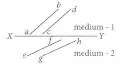
(i) Light travels as a
| (a) parallel beam in each medium | (b) convergent beam in each medium |
| (c) divergent beam in each medium | (d) divergent beam in one medium and convergent beam in the other medium. |
(ii) The phases of the light wave at c, d, e and f are \(\phi_{c}, \phi_{d}, \phi_{e}\) and \( \phi_{f}\) respectively. It is given that \(\phi_{c} \neq \phi_{f}\)
| \(\text { (a) } \phi_{c} \text { cannot be equal to } \phi_{d}\) | \(\text { (b) } \phi_{d} \text { can be equal to } \phi_{e}\) |
| \(\text { (c) }\left(\phi_{d}-\phi_{f}\right) \text { is equal to }\left(\phi_{c}-\phi_{e}\right)\) | \(\text { (d) }\left(\phi_{d}-\phi_{c}\right) \text { is not equal to }\left(\phi_{f}-\phi_{e}\right)\) |
(iii) Wavefront is the locus of all points, where the particles of the medium vibrate with the same
| (a) phase | (b) amplitude | (c) frequency | (d) period |
(iv) A point source that emits waves uniformly in all directions, produces wavefronts that are
| (a) spherical | (b) elliptical | (c) cylindrical | (d) planar |
(v) What are the types of wavefronts ?
| (a) Spherical | (b) Cylindrical | (c) Plane | (d) All of these |
4.
Distance between two successive bright or dark fringes is called fringe width.
\(\beta=Y_{n+1}-Y_{n}=\frac{(n+1) \lambda D}{d}-\frac{n \lambda D}{d}=\frac{\lambda D}{d}\)
Fringe width is independent of the order of the maxima. If whole apparatus is immersed in liquid of refractive index \(\mu\) then \(\beta=\frac{\lambda D}{\mu d}\) (fringe width decreases). Angular fringe width (\(\theta\)) is the angular separation between two consecutive maxima or minima \(\theta=\frac{\beta}{D}=\frac{\lambda}{d}\)
In the arrangement shown in figure, slit S3 and S4 are having a variable separation Z. Point 0 on the screen is at the common perpendicular bisector of S1S2 and S3S4.
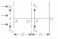
(i) The maximum number of possible interference maxima for slit separation equal to twice the wavelength in Young's double-slit experiment, is
| (a) infinite | (b) five | (c) three | (d) zero |
(ii) In Young's double - slit experiment if yellow light is replaced by blue light, the interference fringes become
| (a) wider | (b) brighter | (c) narrower | (d) darker |
(iii) In Young's double slit experiment, if the separation between the slits is halved and the distance between the slits and the screen is doubled, then the fringe width compared to the unchanged one will be
| (a) Unchanged | (b) Halved | (c) Doubled | (d) Quadrupled |
(iv) When the complete Young's double slit experiment is immersed in water, the fringes
| (a) remain unaltered | (b) become wider | (c) become narrower | (d) disappear |
(v) In a two slit experiment with white light, a white fringe is observed on a screen kept behind the slits. When the screen is moved away by 0.05 m, this white fringe
| (a) does not move at all | (b) gets displaced from its earlier position |
| (c) becomes coloured | (d) disappears |
5.
The potential barrier in the p-n junction diode is the barrier in which the charge recquires additional force for crossing the region. In other words, the barrier in which the charge carrier stopped by the obstructive force is known as the potential barrier.
When a p-type semiconductor is brought into a close contact with n-type semiconductor, we get a p-n junction with a barrier potential 0.4 V and width of depletion region is 4.0 x 10⁻⁷ m. This p-n junction is forward biased with a battery of voltage 3V and negligible internal resistance, in series with a resistor of resistance R, ideal millimeter and key K as shown in figure. When key is pressed, a current of 20 mA passes through the diode.
(i) The intersity of the electric field in the depletion region when p-n junction is unbiased is
| (a) 0.5 x 10⁶ V m-1 | (b) 1.0 x 10⁶ V m-1 | (c) 2.0 x 10⁶ V m-1 | (d) 1.5 x 10⁶ V m-1 |
(ii) The resistance of resistor R is
| (a) 150 \(\Omega\) | (b) 300 \(\Omega\) | (c) l30 \(\Omega\) | (d) 180 \(\Omega\) |
(iii) In a p-n junction, the potential barrier is due to the charges on either side of the junction, these charges are
| (a) majority carriers | (b) minority carriers |
| (c) both (a) and (b) | (d) fixed donor and acceptor ions. |
(iv) If the voltage of the potential barrier is V0 A voltage V is applied to the input, at what moment will the barrier disappear?
| (a) V |
(b) V=V0 | (c) V>V0 | (d) V< |
(v) If an electron with speed 4.0 x 10⁵ m s-1 approaches the p-n junction from the n-side, the speed with which it will enter the p-side is
| (a) 1.39 x 10⁵ m S-1 | (b) 2.78 x 10⁵ m S-1 | (c) 1.39 x 10⁶ m S-1 | (d) 2.78 x 10⁶ m s-1 |
6.
A transformer is an electrical device which is used for changing the a.c. voltages. It is based on the phenomenon of mutual induction i.e. whenever the amount of magnetic flux linked with a coil changes, an e.m.f is induced in the neighbouring coil. For. an ideal transformer, the resistances of the primary and secondary windings are negligible.
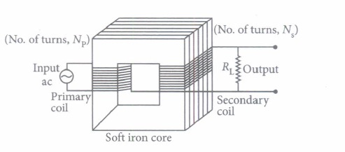
It can be shown that \(\frac{E_{s}}{E_{p}}=\frac{I_{p}}{I_{s}}=\frac{n_{s}}{n_{p}}=k\)
where the symbols have their standard meanings.
For a step up transformer \(n_{s}>n_{p} ; E_{s}>E_{p} ; k>1 ; \quad \therefore I_{s}
For a step down transformer \(n_{s}
The above relations are on the assumptions that efficiency of transformer is 100%.
lentlac ,effciency \(\eta=\frac{\text { output power }}{\text { intput power }}=\frac{E_{s} I_{s}}{E_{p} I_{p}}\)
(i) Which of the following quantity remains constant in an ideal transformer?
| (a) Current | (b) Voltage | (c) Power | (d) All of these |
(ii) Transformer is used to
| (a) convert ac to dc voltage | (b) convert de to ac voltage |
| (c) obtain desired dc power | (d) obtain desired ac voltage and current |
(iii) The number of turns in primary coil of a transformer is 20 and the number of turns in a secondary is 10. If the voltage across the primary is 220 ac V, what is the voltage across the secondary?
| (a) 100 ac V | (b) 120 ac V | (c) 110 ac V | (d) 220 ac V |
(iv) In a transformer the number of primary turns is four times that of the secondary turns. Its primary is connected to an a.c. source of voltage V. Then
| (a) current through its secondary is about four times that of the current through its primary |
| (b) voltage across its secondary is about four times that of the voltage across its primary. |
| (c) voltage across its secondary is about two times that of the voltage across its primary |
| (d) voltage across its secondary is about \(\frac{1}{2 \sqrt{2}}\) times that of the voltage across its primary |
(v) A transformer is used to light 100 W-110 V lamp from 220 V mains. If the main current is 0.5 A, the efficiency of the transformer is
| (a) 95% | (b) 99% | (c) 90% | (d) 96% |
7.
At room temperature, most of the H-atoms are in ground state. When an atom receives some energy (i.e., by electron collisions), the atom may acquire sufficient energy to raise electron to higher energy state. In this condition, the atom is said to be in excited state. From the excited state, the electron can fall back to a state of lower energy emitting a photon equal to the energy difference of the orbit.
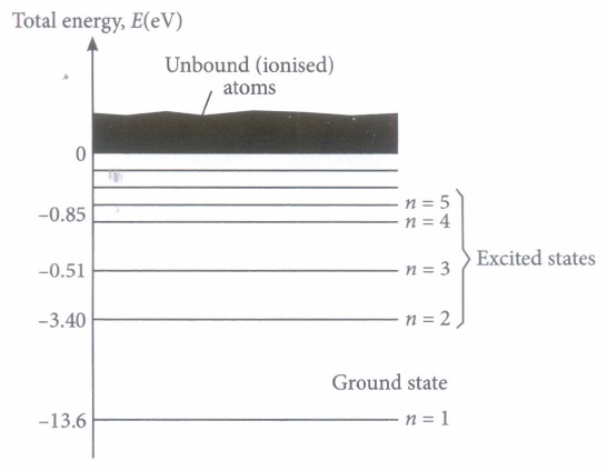
In a mixture of H-He+ gas (He+ is single ionized He atom), H-atoms and He+ ions are excited to their respective first excited states. Subsequently, H-atoms transfer their total excitation energy to He+ ions (by collisions).
(i) The quantum number n of the state finally populated in He+ ions is
| (a) 2 | (b) 3 | (c) 4 | (d) 5 |
(ii) The wavelength of light emitted in the visible region by He+ ions after collisions with H-atoms is
| (a) 6.5 x 10⁻⁷ m | (b) 5.6 x 10⁻⁷ m | (c) 4.8 x 10⁻⁷ m | (d) 4.0 x 10⁻⁷ m |
(iii) The ratio of kinetic energy of the electrons for the H-atoms to that of He+ ion for n = 2 is
| \(\text { (a) } \frac{1}{4}\) | \(\text { (b) } \frac{1}{2}\) | (c) 1 | (d) 2 |
(iv) The radius ofthe ground state orbit of H-atoms is
| \(\text { (a) } \frac{\varepsilon_{0}}{h \pi m e^{2}}\) | \(\text { (b) } \frac{h^{2} \varepsilon_{0}}{\pi m e^{2}}\) | \(\text { (c) } \frac{\pi m e^{2}}{h}\) | \(\text { (d) } \frac{2 \pi h \varepsilon_{0}}{m e^{2}}\) |
(v) Angular momentum of an electron in H-atom in first excited state is
| \(\text { (a) } \frac{h}{\pi}\) | \(\text { (b) } \frac{h}{2 \pi}\) | \(\text { (c) } \frac{2 \pi}{h}\) | \(\text { (d) } \frac{\pi}{h}\) |
8.
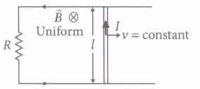
The emf induced across the ends of a conductor due to its motion in a magnetic field is called motional emf. It is produced due to the magnetic Lorentz force acting on the free electrons of the conductor. For a circuit shown in figure, if a conductor of length I moves with velocity v in a magnetic field B perpendicular to both its length and the direction of the magnetic field, then all the induced parametres are possible in the circuit.
(i) Direction of current induced in a wire moving in a magnetic field is found using
| (a) Fleming's left hand rule | (b) Fleming's right hand rule |
| (c) Ampere's rule | (d) Right hand clasp rule |
(ii) A conducting rod of length I is moving in a transverse magnetic field of strength B with velocity v. The resistance of the rod is R. The current in the rod is
| \(\text { (a) } \frac{B l v}{R}\) | (b) Blv | (c) zero | \(\text { (d) } \frac{B^{2} v^{2} l^{2}}{R}\) |
(iii) A 0.1 m long conductor carrying a current of 50 A is held perpendicular to a magnetic field of 1.25 mT. The mechanical power required to move the conductor with a speed of 1 m s-1 is
| (a) 62.5 mW | (b) 625 mW | (c) 6.25 mW | (d) 12.5 mW |
(iv) A bicycle generator creates 1.5 V at 15 km/hr. The EMF generated at 10 km/hr is
| (a) 1.5 volts | (b) 2volts | (c) 0.5volts | (d) 1 volt |
(v) The dimensional formula for emf E in MKS system will be
| \(\text { (a) }\left[\mathrm{ML}^{2} \mathrm{~T}^{-3} \mathrm{~A}^{-1}\right]\) | \(\text { (b) }\left[\mathrm{ML}^{2} \mathrm{~T}^{-1} \mathrm{~A}\right]\) | \(\text { (c) }\left[\mathrm{ML}^{2} \mathrm{~A}\right]\) | \(\text { (d) }\left[\mathrm{MLT}^{-2} \mathrm{~A}^{-2}\right]\) |
9.
If we allow radiations of a fixed frequency to fall on plate and the accelerating potential difference between the two electrodes is kept fixed, then the photoelectric current is found to increase linearly with the intensity of incident radiation. Here, radiation pressure is P = \(\left(\frac{1+e}{C}\right) I\). As, atmosphere pressure at sea level is 105Pa. If the intensity of light of a given wavelength, is increased, there is an increase in the number of photons incident on a given area in a given time. But the energy of each photon remain the same.
(i) The number of photons hitting the cone second
| \(\text { (a) } \pi R^{2} I / 2 E\) | \(\text { (b) } 2 \pi R^{2} I / E\) | \(\text { (c) } \pi R^{2} I / 4 E\) | \(\text { (d) } \pi R^{2} I / E\) |
(ii) A radiation of energy E falls normally on a perfect reflecting surface. The momentum transferred to the surface is
| \(\text { (a) } \frac{E}{c}\) | \(\text { (b) } \frac{2 E}{c}\) | \(\text { (c) } E c\) | \(\text { (d) } \frac{E}{c^{2}}\) |
(iii) Which one is correct?
| \(\text { (a) } E^{2}=p^{2} c^{2}\) | \(\text { (b) } E^{2}=p^{2} c\) | \(\text { (c) } E^{2}=p^{2}\) | \(\text { (d) } E^{2}=\frac{p^{2}}{c^{2}}\) |
(iv) The incident intensity on a horizontal surface at sea level from the Sun is about 1 k W m-2. Assuming that 50% of this intensity is reflected and 50% is absorbed, determine the radiation pressure on this horizontal surface.
| (a) 8.2 x 10⁻² Pa | (b) 5 x 10⁻⁶ Pa | (c) 3 x 10⁻⁵ Pa | (d) 6 x 10⁻⁵ Pa |
(v) Find the ratio of radiation pressure to atmospheric pressure P0 about 1 x 10⁵ Pa at sea level.
| (a) 5 x 10-11 | (b) 4 x 10⁻⁸ | (c) 6 x 10-12 | (d) 8 x 10-11 |
10.
The magnetic field lines of the earth resemble that of a hypothetical magnetic dipole located at the centre of the earth. The axis of the dipole is presently tilted by approximately 11.3o with respect to the axis of rotation of the earth.
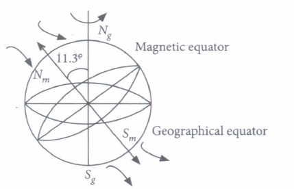
The pole near the geographic North pole of the earth is called the North magnetic pole and the pole near the geographic South pole is called South magnetic pole.
(i) The strength of the earth's magnetic field varies from place to place on the earth's surface, its value being of the order of
| (a) 105 T | (b) 10-6T | (c) 10-5 T | (d) 108 T |
(ii) A bar magnet is placed North-South with its North-pole due North. The points of zero magnetic field will be in which direction from centre of magnet?
| (a) North-South | (b) East-West |
| (c) North-East and South-West | (d) None of these. |
(iii) The value of angle of dip is zero at the magnetic equator because on it
| (a) V and H are equal | (b) the values of Vand H zero |
| (c) the value of V is zero | (d) the value of H is zero . |
(iv) The angle of dip at a certain place, where the horizontal and vertical components of the earth's magnetic field are equal, is
| (a) 30° | (b) 90° | (c) 60° | (d) 45° |
(v) At a place, angle of dip is 30°. If horizontal component of earth's magnetic field is H, then the total intensity of magnetic field will be
| (a) \(\frac{H}{2}\) | \(\text { (b) } \frac{2 H}{\sqrt{3}}\) | \(\text { (c) } H \sqrt{\frac{3}{2}}\) | (d) 2H |
11.
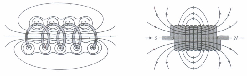
A solenoid is a long coil of wire tightly wound in the helical form. Solenoid consists of closely stacked rings electrically insulated from each other wrapped around a non-conducting cylinder.
Figure below shows the magnetic field lines of a solenoid carrying a steady current 1.We see that if the turns are closely spaced, the resulting magnetic field inside the solenoid becomes fairly uniform, provided that the length of the solenoid is much greater than its diameter, For an "ideal" solenoid, which is infinitely long with turns tightly packed, the magnetic field inside the solenoid is uniform and parallel to the axis, and vanishes outside the solenoid.
(i) Along solenoid has 800 turns per metre length of solenoid. A current of 1.6A flows through it. The magnetic induction at the end of the solenoid on its axis is
| (a) 16 x 10-4 T | (b) 8 x 10⁻⁴ T | (c) 32 X 10-4 T | (d) 4 x 10⁻⁴ T |
(ii) Choose the correct statement in the following
| (a) The magnetic field inside the solenoid is less than that of outside |
| (b) The magnetic field inside an ideal solenoid is not at all uniform |
| (c) The magnetic field at the centre, inside an ideal solenoid is atmost twice that at the ends |
| (d) The magnetic field at the centre, inside an ideal solenoid is almost half of that at the ends |
(iii) The magnetic field (B) inside a long solenoid having n turns per unit length and carrying current I when iron core is kept in it is \(\left(\mu_{0}=\text { permeability of vacuum, } \chi=\right.\text { magnetic susceptibility) }\)
| \(\text { (a) } \mu_{0} n I(1-\chi)\) | \(\text { (b) } \mu_{0} n I \chi\) | \(\text { (c) } \mu_{0} n I^{2}(1+\chi)\) | \(\text { (d) } \mu_{0} n I(1+\chi)\) |
(iv) A solenoid oflength I and having n turns carries a current I is in anticlockwise direction. The magnetic field is
| \(\text { (a) } \mu_{0} n I\) | \(\text { (b) } \mu_{0} \frac{n I}{l^{2}}\) |
| (c) along the axis of solenoid | (d) perpendicular to the axis of coil |
(v) The magnitude of the magnetic field inside a long solenoid is increased by
| (a) decreasing its radius | (b) decreasing the current through it |
| (c) increasing its area of cross-section | (d) introducing a medium of higher permeability |
12.
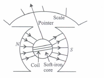
Moving coil galvanometer operates on Permanent Magnet Moving Coil (PMMC) mechanism and was designed by the scientist D'arsonval.
Moving coil galvanometers are of two types
(i) Suspended coil
(ii) Pivoted coil type or tangent galvanometer.
Its working is based on the fact that when a current carrying coil is placed in a magnetic field, it experiences a torque. This torque tends to rotate the coil about its axis of suspension in such a way that the magnetic flux passing through the coil is maximum.
(i) A moving coil galvanometer is an instrument which
| (a) is used to measure emf |
| (b) is used to measure potential difference |
| (c) is used to measure resistance |
| (d) is a deflection instrument which gives a deflection when a current flows through its coil |
(ii) To make the field radial in a moving coil galvanometer
| (a) number of turns of coil is kept small | (b) magnet is taken in the form of horse-shoe |
| (c) poles are of very strong magnets | (d) poles are cylindrically cut |
(iii) The deflection in a moving coil galvanometer is
| (a) directly proportional to torsional constant of spring |
| (b) directly proportional to the number of turns in the coil |
| (c) inversely proportional to the area of the coil |
| (d) inversely proportional to the current in the coil |
(iv) In a moving coil galvanometer, having a coil of N-turns of area A and carrying current I is placed in a radial field of strength B.
The torque acting on the coil is
| \(\text { (a) } N A^{2} B^{2} I\) | \(\text { (b) } N A B I^{2}\) | \(\text { (c) } N^{2} A B I\) | (d) NABI |
(v) To increase the current sensitivity of a moving coil galvanometer, we should decrease
| (a) strength of magnet | (b) torsional constant of spring |
| (c) number ofturns in coil | (d) area of coil |
13.
The path of a charged particle in magnetic field depends upon angle between velocity and magnetic field.If velocity \(\vec{v}\) is at angle \(\theta\) to \(\vec{B}\) component of velocity parallel to magnetic field \((v \cos \theta)\) remains constant and component of velocity perpendicular to magnetic field \((v \sin \theta)\) is responsible for circular motion, thus the charge particle moves in a helical path.
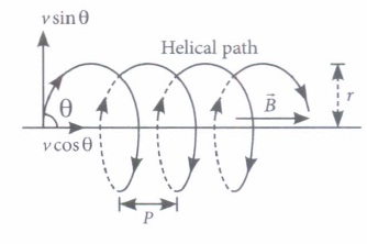
The plane of the circle is perpendicular to the magnetic field and the axis of the helix is parallel to the magnetic field. The charged particle. moves along helical path touching the line parallel to the magnetic field passing through the starting point after each rotation.
Radius of circular path is \(r=\frac{m v \sin \theta}{1 v_{q} B}\)
Hence the resultant path of the charged particle will be a helix, with its axis along the direction of \(\vec{B}\) as shown in figure.
(i) When a positively charged particle enters into a uniform magnetic field with uniform velocity, its trajectory can be (i) a straight line (ii) a circle (iii) a helix.
| (a) (i) only | (b) (i) or (ii) |
| (c) (i) or (iii) | (d) anyone of (i), (ii) and (iii) |
(ii) Two charged particles A and B having the same charge, mass and speed enter into a magnetic field in such a way that the initial path of A makes an angle of 30° and that of B makes an angle of 90° with the field. Then the trajectory of
| (a) B will have smaller radius of curvature than that of A |
| (b) both will have the same curvature |
| (c) A will have smaller radius of curvature than that of B |
| (d) both will move along the direction of their original velocities. |
(iii) An electron having momentum 2.4 x 10⁻²³kg m/ s enters a region of uniform magnetic field of 0.15 T. The field vector makes an angle of 30° with the initial velocity vector of the electron. The radius of the helical path of the electron in the field shall be
| (a) 2 mm | (b) 1 mm | \(\text { (c) } \frac{\sqrt{3}}{2} \mathrm{~mm}\) | (d) 0.5 mm |
(iv) The magnetic field in a certain region of space is given by \(\vec{B}=8.35 \times 10^{-2} \hat{i}\) T. A proton is shot into the field with velocity \(\vec{v}=\left(2 \times 10^{5} \hat{i}+4 \times 10^{5} \hat{j}\right) \mathrm{m} / \mathrm{s}\) The proton follows a helical path in the field. The distance moved by proton in the x-direction during the period of one revolution in the yz-plane will be
(Mass of proton = 1.67 x 10⁻²⁷kg)
| (a) 0.053 m | (b) 0.136 m | (c) 0.157 m | (d) 0.236 m |
(v) The frequency of revolution of the particle is
| \(\text { (a) } \frac{m}{q B}\) | \(\text { (b) } \cdot \frac{q B}{2 \pi m}\) | \(\text { (c) } \frac{2 \pi R}{v \cos \theta}\) | \(\text { (d) } \frac{2 \pi R}{v \sin \theta}\) |
14.
According to Ohm's law, the current flowing through a conductor is directly proportional to the potential difference across the ends of the conductor i.e \(I \propto V \Rightarrow \frac{V}{I}=R\) where R is resistance of the conductor Electrical resistance of a conductor is the obstruction posed by the conductor to the flow of electric current through it. It depends upon length, area of cross-section, nature of material and temperature of the conductor We can write \(R \propto \frac{l}{A} \text { or } R=\rho \frac{l}{A}\) where \(\rho\) is electrical resistivity of the material of the conductor.
(i) Dimensions of electric resistance is
| \(\text { (a) }\left[\mathrm{ML}^{2} \mathrm{~T}^{-2} \mathrm{~A}^{-2}\right]\) | \(\text { (b) }\left[M L^{2} T^{-3} A^{-2}\right]\) | \(\text { (c) }\left[\mathrm{M}^{-1} \mathrm{~L}^{-2} \mathrm{~T}^{-1} \mathrm{~A}\right]\) | \(\text { (d) }\left[M^{-1} L^{2} T^{2} A^{-1}\right]\) |
(ii) If \(1 \mu \mathrm{A}\) current flows through a conductor when potential difference of2 volt is applied across its ends, then the resistance of the conductor is
| \(\text { (a) } 2 \times 10^{6} \Omega\) | \(\text { (b) } 3 \times 10^{5} \Omega\) | \(\text { (c) } 1.5 \times 10^{5} \Omega\) | \(\text { (d) } 5 \times 10^{7} \Omega\) |
(iii) Specific resistance of a wire depends upon
| (a) length | (b) cross-sectional area | (c) mass | (d) none of these |
(iv) The slope of the graph between potential difference and current through a conductor is
| (a) a straight line | (b) curve |
| (c) first curve then straight line | (d) first straight line then curve |
(v) The resistivity of the material of a wire 1.0 m long, 0.4 mm in diameter and having a resistance of 2.0 ohm is
| \(\text { (a) } 1.57 \times 10^{-6} \Omega \mathrm{m}\) | \(\text { (b) } 5.25 \times 10^{-7} \Omega \mathrm{m}\) | \(\text { (c) } 7.12 \times 10^{-5} \Omega \mathrm{m}\) | \(\text { (d) } 2.55 \times 10^{-7} \Omega \mathrm{m}\) |
15.
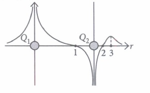
The potential at any observation point P of a static electric field is defined as the work done by the external agent (or negative of work done by electrostatic field) in slowly bringing a unit positive point charge from infinity to the observation point. Figure shows the potential variation along the line of charges. Two point charges Q1 and Q2 lie along a line at a distance from each other.
(i) At which of the points 1, 2 and 3 is the electric field is zero?
| (a) 1 | (b) 2 | (c) 3 | (d) Both (a) and (b) |
(ii) The signs of charges Q1 and Q2 respectively are
| (a) positive and negative | (b) negative and positive |
| (c) positive and positive | (d) negative and negative |
(iii) Which of the two charges Q1 and Q2 is greater in magnitude?
| (a) Q2 | (b) Q1 | (c) Same | (d) Can't determined |
(iv) Which of the following statement is not true?
| (a) Electrostatic force is a conservative force |
| (b) Potential energy of charge q at a point is the work done per unit charge in bringing a charge from any point to infinity |
| (c) When two like charges lie infinite distance apart, their potential energy is zero. |
| (d) Both (a) and (c). |
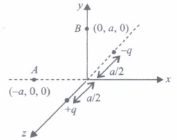
(v) Positive and negative point charges of equal magnitude are kept at \(\left(0,0, \frac{a}{2}\right)\) and \(\left(0,0, \frac{-a}{2}\right)\) respectively.
The work done by the electric field when another positive point charge is moved from (-a, 0, 0) to (0, a, 0) is
| (a) positive |
| (b) negative |
| (c) zero |
| (d) depends on the path connecting the initial and final positions |
1.
(i) (b): Infrared rays can be converted into electric energy as in solar cell.
(ii) (d): Radiowaves have longest wavelength.
(iii) (c) : Cathode rays are invisible fast moving streams of electrons emitted by the cathode of a discharge tube which is maintained at a pressure of about 0.01 mm of mercury.
(iv) (c): \(\Upsilon\)-rays have minimum wavelength
(v) (a): \(\lambda_{\text {micro }}>\lambda_{\text {infra }}>\lambda_{\text {ultra }}>\lambda_{\text {gamma }}\)
2.
(i) (b): Here, \(f_{0}=2.0, f_{e}=6.25 \mathrm{~cm}, u_{0}=?\)
When the final image is obtained at the least distance of distinct vision:
Ve = - 25 cm
\(\text {As } \frac{1}{v_{e}}-\frac{1}{u_{e}}=\frac{1}{f_{e}} \)
\(\therefore \ \frac{1}{u_{e}}=\frac{1}{v_{e}}-\frac{1}{f_{e}}=\frac{1}{-25}-\frac{1}{6.25} \)
\(=\frac{-1-4}{25}=\frac{-5}{25}=-\frac{1}{5} \)
\(\text {or } u_{e}=-5 \mathrm{~cm}\)
(ii) (b): Distance between objective and eye-piece = 15cm
\(\therefore\) Distance of the image from objective is
\(v_{0}=15-5=10 \mathrm{~cm} \)
\(\therefore \quad \frac{1}{u_{0}}=\frac{1}{v_{0}}-\frac{1}{f_{0}}=\frac{1}{10}-\frac{1}{2}=\frac{1-5}{10}=-\frac{2}{5} \)
\(\text {or } \ u_{0}=-\frac{5}{2}=-2.5 \mathrm{~cm}\)
\(\therefore\) Distance of object from objective = 2.5 cm
(iii) (a): Magnifying power
\(m=m_{0} \times m_{e}=\frac{v_{0}}{u_{0}}\left(1+\frac{D}{f_{e}}\right)=\frac{10}{2.5}\left(1+\frac{25}{6.25}\right)=20\)
(iv) (a): The intermediate image formed, by the objective of a compound microscope is real, inverted and magnified.
(v) (d)
3.
(i) (a): Since the path difference between two waveform is equal, light traves as parallel beam in each medium.
(ii) (c): Since all points on the wavefront are in the same phase,
\(\phi_{d}=\phi_{c} \text { and } \phi_{f}=\phi_{e} \)
\(\therefore \phi_{d}-\phi_{f}=\phi_{c}-\phi_{e^{-}}\)
(iii) (a): Wavefront is the locus of all points, where the particles of the medium vibrate with the same phase
(iv) (a)
(v) (d)
4.
(i) (b): The condition for possible interference maxima on the screen is, dsin\(\theta\) = nA
where d is slit separation and Ais the wavelength.
As d = 2\(\lambda\) (given) \(\therefore\) 2\(\lambda\)sin\(\theta\)= n\(\lambda\) or 2sin\(\theta\) = n
For number of interference maxima to be maximum,
sin\(\theta\) = 1 \(\therefore\) n = 2
The intprference maxima will be forgied when
n = 0, ± 1, ± 2
Hence the maximum number of possible maxima is 5.
(ii) (c): Fringe width, \(\beta=\frac{\lambda D}{d}\)
\(\therefore\) If we replace yellow light with blue light, i.e., longer wavelength with shorter one, therefore the fringe width decreases.
(iii) (d): \(d^{\prime}=\frac{d}{2} \text { and } D^{\prime}=2 D\)
Fringe width, \(\beta=\frac{\lambda D}{d}\)
New fringe width \(\beta^{\prime}=\lambda\left(\frac{2 D}{d / 2}\right)=4 \beta\)
(iv) (c): When Young's double slit experiment is repeated in water, instead of air \(\lambda^{\prime}=\frac{\lambda}{\mu}\) i.e., wavelength decreases.\(\beta=\frac{\lambda^{\prime} D}{d}\) i.e..,fringe width decreases.
\(\therefore\) The fringe become narrower.
(v) (a): Using white light, we get white fringe at the centre i.e., white fringe is the central maximum. When the screen is moved, its position is not changed.
5.
(i) (b) : \(E=\frac{V_{B}}{d}=\frac{0.4}{4.0 \times 10^{-7}}=1.0 \times 10^{6} \mathrm{Vm}^{-1}\)
(ii) (c) : Potential difference across = R = 3 - 0.4 = 2.6 V
\(\text { Resistance } R=\frac{\text { Potential difference }}{\text { Current }}\)
\(=\frac{2.6}{20 \times 10^{-3}}=130 \Omega\)
(iii) (d)
(iv) (b) : When the voltage will be the same that of the potential barrier disappears resulting in flow of current.
(v) (a) : \(\frac{1}{2} m v_{1}^{2}=e V_{B}+\frac{1}{2} m v_{2}^{2}\)
\(\Rightarrow \frac{1}{2} \times\left(9.1 \times 10^{-31}\right) \times\left(4 \times 10^{5}\right)^{2}\)
\(=1.6 \times 10^{-19} \times(0.4)+\frac{1}{2} \times 9.1 \times 10^{-31} \times v_{2}^{2}\)
On solving, we get
\(v_{2}=1.39 \times 10^{5} \mathrm{~m} \mathrm{~s}^{-1}\)
6.
(i) (c) :In an ideal transformer, there is no power loss. The efficiency of an ideal transformer is \(\eta=1(i . e\) 100%) i.e. input power = output power.
(ii) (d): Transformer is used to obtain desired ac voltage and current.
(iii) (c): For a transformer \(\frac{V_{s}}{V_{p}}=\frac{N_{s}}{N_{p}}\)
where Ndenotes number of turns and V = voltage
\(\therefore \frac{V_{s}}{220}=\frac{10}{20} \quad \therefore V_{s}=110 \mathrm{ac} \mathrm{V}\)
(iv) (a): In a transformer the primary and secondary currents are related by
\(I_{s}=\left(\frac{N_{p}}{N_{s}}\right) I_{p}\)
and the voltages are related by
\(V_{s}=\left(\frac{N_{s}}{N_{p}}\right) V_{p}\)
where subscripts p and s refer to the primary and secondary of the transformer
Here, \(V_{p}=V, \frac{N_{p}}{N_{s}}=4 \quad \therefore \quad I_{s}=4 I_{p}\)
and \(V_{s}=\left(\frac{1}{4}\right) V=\frac{V}{4}\)
(v) (c): The efficiency of the transformer is \(\eta=\frac{\text { Output power }\left(P_{\text {out }}\right)}{\text { Input power }\left(P_{\text {in }}\right)} \times 100\)
Here, \(P_{\text {out }}=100 \mathrm{~W}, P_{\text {in }}=(220 \mathrm{~V})(0.5 \mathrm{~A})=110 \mathrm{~W}\)
\(\therefore \quad \eta=\frac{100 \mathrm{~W}}{110 \mathrm{~W}} \times 100 \approx 90 \%\)
7.
(i) (c) : \(E_{n}=\frac{-13.6}{n^{2}}\left(Z^{2}\right)\)
In first excited state \(E_{\mathrm{H}_{2}}=3.4 \mathrm{eV} \text { and } E_{\mathrm{He}}=-13.6 \mathrm{eV}\)
So, H2 atom gives excitation energy
(13.6- 3.4 = 10.2 eV) to helium atom
Now, energy of He ion = -13.6 + 10.2 = -3.4 eV
Again, \(E=\frac{-13.6}{n^{2}} \times Z^{2}\)
\(\Rightarrow \quad-3.4=\frac{-13.6}{n^{2}} \times(2)^{2} \Rightarrow n=4\)
(ii) (c): \(\frac{1}{\lambda}=\frac{13.6 Z^{2}}{h c}\left[\frac{1}{n_{1}^{2}}-\frac{1}{n_{2}^{2}}\right]\)
Here, \(n_{1}=3 \text { and } n_{2}=4 \Rightarrow \lambda=4.8 \times 10^{-7} \mathrm{~m}\)
(iii) (a): \(\text { Kinetic energy, } K \propto \frac{Z^{2}}{n^{2}}\)
\(\frac{K_{\mathrm{H}_{2}}}{K_{\mathrm{He}}}=\left(\frac{Z_{\mathrm{H}_{2}}}{Z_{\mathrm{He}}}\right)^{2}=\left(\frac{1}{2}\right)^{2}=\frac{1}{4}\)
(iv) (b): Radius of the permitted orbit is \(r=\frac{n^{2} h^{2} \varepsilon_{0}}{\pi m Z e^{2}}\) For hydrogen atom in ground state, i.e.,|
\(n=1, Z=1 \Rightarrow r=\frac{h^{2} \varepsilon_{0}}{\pi m e^{2}}\)
(v) (a): Angular momentum for hydrogen atom is
\(L=\frac{n h}{2 \pi}\)
For first excited state \(n=2, \quad L=\frac{h}{\pi}\)
8.
(i) (b) : Direction of current induced in a wire moving in a magnetic field is found by using Fleming's right hand rule.
(ii) (a) : Induced e.m.f, E = Blv
Current in the rod, \(I=\frac{\varepsilon}{R}=\frac{B l v}{R}\)
(iii) (c) : Here, L = 0.1 m, v = 1m s-1
\(I=50 \mathrm{~A}, B=1.25 \mathrm{mT}=1.25 \times 10^{-3} \mathrm{~T}\)
The induced emf is, E = Blv
The mechanical power is \(P=\varepsilon I=B l v I=1.25 \times 10^{-3} \times 0.1 \times 1 \times 50\)
\(=6.25 \times 10^{-3} \mathrm{~W}=6.25 \mathrm{~mW}\)
(iv) (d): Emf induced, E = Blv
Here, \(\vec{B}, \vec{l}\) and \(\vec{v}\) are mutually perpendicular
For given B and l,\(\varepsilon \propto v\)
\(\therefore \quad \frac{\varepsilon_{1}}{\varepsilon_{2}}=\frac{v_{1}}{v_{2}}\)
Here, \(\varepsilon_{1}=1.5 \mathrm{~V}, v_{1}=15 \mathrm{~km} / \mathrm{hr}=15 \times \frac{5}{18} \mathrm{~ms}^{-1}\)
\(v_{2}=10 \mathrm{~km} / \mathrm{hr}=10 \times \frac{5}{18} \mathrm{~ms}^{-1}, \varepsilon_{2}=?\)
So,\(\frac{1.5}{\varepsilon_{2}}=\frac{15 \times \frac{5}{18}}{10 \times \frac{5}{18}}=\frac{3}{2} ; \quad \varepsilon_{2}=1 \mathrm{~V}\)
(v) (a): \(\varepsilon=\frac{[W]}{[q]}=\frac{M L^{2} T^{-2}}{A T}=M L^{2} T^{-3} A^{-1}\)
9.
(i) (d): Power of light received by the cone \(=I\left(\pi R^{2}\right)\)
Let number of photons hitting the cone per second is n.
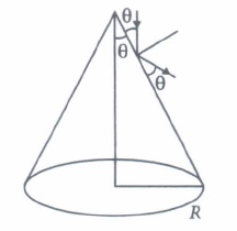
Then, \(n E=I \pi R^{2} \Rightarrow n=\pi R^{2} I / E\)
(ii) (b): Initial moment \(p_{i}=\frac{E}{c}\)
For a perfectly selecting surface
Final momentum \(p_{f}=\frac{-E}{c}\)
\(\Delta p=p_{f}-p_{i}=\frac{-E}{c}-\frac{E}{c}=\frac{-2 E}{c}\)
Hence a momentum \(\frac{2 E}{c}\) is transferred to the reflecting surface.
(iii) (a): According to the theory of relatively,
\(E=m c^{2}=m c . c=p c\)
\(\text { or } \quad E^{2}=p^{2} c^{2}\)
where p is the momentum of a photon.
(iv) (b): I = 1 kWm-2
As, 50% of light is reflected, thus e = 0.5
Radiation pressure \(P=\frac{(1+e) I}{c}\)
\(\therefore \quad P=\frac{(1+0.5) \times 1000}{3 \times 10^{8}}=5 \times 10^{-6} \mathrm{~Pa}\)
(v) (a) : \(\frac{P_{\mathrm{rad}}}{P_{0}}=\frac{5 \times 10^{-6}}{1 \times 10^{5}}=5 \times 10^{-11}\)
10.
(i) (c)
(ii) (b)
(iii) (c) : At equator vertical component of magnetic fields is zero.
(iv) (d): Given: V = H
\(\therefore \tan \delta=\frac{V}{H}=1 \text { or } \delta=45^{\circ}\)
(v) (b): Given : Biot-Savart law can be expressed alternatively as Ampere circuital law
11.
(i) (b): As B = \(\frac{\mu_{0} n I}{2}=\frac{\left(4 \pi \times 10^{-7}\right) \times 800 \times 1.6}{2}\)
= 8 x 10⁻⁴ T
(ii) (c): Magnetic field at one end of a solenoid carrying current is \(B=\frac{\mu_{0} n I}{2}\)
Magnetic field inside the solenoid is uniform and is given by \(B_{c}=\mu_{0} n I\)
(iii) (d): Magnetic field inside a long solenoid with an iron core inside it is \(B=\mu n I\)
But \(\mu=\mu_{0}(1+\chi) \quad \therefore \quad B=\mu_{0}(1+\chi) n I\)
(iv) (c): A solenoid of length I and having n turns carries a current I in anticlockwise direction. The magnetic field is \(\frac{\mu_{0} n I}{l}\) Its direction will be along the axis of solenoid
(v) (d)
12.
(I) (d): A moving coil galvanometer is a sensitive instrument which is used to measure a deflection when a current flows through its coil.
(ii) (d): Uniform field is made radial by cutting pole pieces cylindrically.
(iii) (b): The deflection in a moving coil galvanometer \(\phi=\frac{N A B}{k} \cdot I \text { or } \phi \propto N\) where Nis number of turns in a coil, B is magnetic field and A is area of cross-section.
(iv) (d): The deflecting torque acting on the coil
\(\tau_{\text {deflection }}=N I A B\)
(v) (b): Current sensitivity of galvanometer
\(\frac{\phi}{I}=S_{i}=\frac{N B A}{k}\)
Hence, to increase (current sensitivity) Si (torsional constant of spring) k must be decrease.
13.
(i) (d)
(ii) (a): Using \(q v B \sin \theta=\frac{m v^{2}}{r}\)
\(r \propto \frac{1}{\sin \theta}\) for the same values of m, v, q and B
\(\therefore \frac{r_{A}}{r_{B}}=\frac{\sin 90^{\circ}}{\sin 30^{\circ}}=2 \text { or } r_{A}=2 r_{B} \text { or } r_{B}<r_{A}\)
(iii) (d): The radius of the helical path of the electron in the uniform magnetic field is
\(r=\frac{m v_{\perp}}{e B}=\frac{m v \sin \theta}{e B}=\frac{\left(2.4 \times 10^{-23} \mathrm{~kg} \mathrm{~m} / \mathrm{s}\right) \times \sin 30^{\circ}}{\left(1.6 \times 10^{-19} \mathrm{C}\right) \times 0.15 \mathrm{~T}}\)
\(=5 \times 10^{-4} \mathrm{~m}=0.5 \times 10^{-3} \mathrm{~m}=0.5 \mathrm{~mm}\)
(iv) (c): Here \(\vec{B}=8.35 \times 10^{-2} \hat{i} \mathrm{~T}\)
\(\vec{v}=2 \times 10^{5} \hat{i}+4 \times 10^{5} \hat{j} \mathrm{~m} / \mathrm{s}, m=1.67 \times 10^{-27} \mathrm{~kg}\)
Pitch of the helix (i.e., the linear distance moved along the magnetic field in one rotation) is given by
Pitch of the helix \(=\frac{2 \pi m v_{\|}}{q B}\)
\(=\frac{2 \times 3.14 \times 1.67 \times 10^{-27} \times 2 \times 10^{5}}{1.6 \times 10^{-19} \times 8.35 \times 10^{-2}}=0.157 \mathrm{~m}\)
(v) (b): Period of revolution
\(T=\frac{2 \pi R}{v \sin \theta} \Rightarrow T=\frac{2 \pi\left(\frac{m v \sin \theta}{q B}\right)}{v \sin \theta} \Rightarrow T=\frac{2 \pi m}{q B}\)
\(\therefore \text { Frequency, } v=\frac{1}{T}=\frac{q B}{2 \pi m}\)
14.
(i) (b)
(ii) (a): \(R=\frac{V}{I}=\frac{2}{10^{-6}}=2 \times 10^{6} \Omega\)
(iii) (d): Specific resistance depends upon the nature of material and is independent of mass and dimensions of the material
(iv) (a)
(v) (d): l = 1.0 m; D = 0.4 mm = 4 x 10⁻⁴m
\(R=2 \Omega\)
\(A=\frac{\pi D^{2}}{4}=\frac{\pi \times\left(4 \times 10^{-4}\right)^{2}}{4}=4 \pi \times 10^{-8} \mathrm{~m}^{2}\)
Now, \(\rho=\frac{R A}{l}=\frac{2 \times 4 \pi \times 10^{-8}}{1}=2.55 \times 10^{-7} \Omega \mathrm{m}\)
15.
(I) (c) : As \(\frac{-d V}{d r}=E_{r}\) the negative of the slope of V versus r curve represents the component of electric field along r. Slope of curve is zero only at point 3. Therefore, the electric field vector is zero at point 3.
(ii) (a) : Near positive charge, net potential is positive and near a negative charge, net potential is negative. Thus, charge Q1 is positive and Q2 is negative.
(iii) (b) : From the figure, it can be seen that net potential due to two charges is positive everywhere in the region left to charge Q1. Therefore the magnitude of potential due to charge Q1 is greater than due to Q2.
(iv) (b)
(v) (c) : It can be seen that potential at the points both A and B are zero. When the charge is moved from A to B, work done by the electric field on the charge will be zero.

12th Standard CBSE Syllabus & Materials
12th Standard CBSE
CBSE 12th Computer Science Python Revision Tour I - New Previous year Question Papers Study Material - QB365 Set A
NEW12th Standard CBSE
CBSE 12th Business Studies Planning Important Questions And Answers Study Material - QB365 Set A
NEW12th Standard CBSE
CBSE 12th Business Studies Business Environment Important Questions And Answers Study Material - QB365 Set A
NEW12th Standard CBSE
CBSE 12th Business Studies Principles of Management Important Questions And Answers Study Material - QB365 Set A



NCERT Books

Syllabus

Exam Pattern

Sample Question Papers

Previous year Question Papers

Important Notes

MCQ Practice test

NCERT Exemplers

Case study Questions

Image Based Questions

Passage based Questions

HOT Questions

Value Based Questions

Model Questions Papers
NCERT ( Book Back ) Questions

Assertion and Reason
Important Questions And Answers

CBSE 12th Standard CBSE Subjects
CBSE Standards